Lessons
This is the course outline.
Matt B. Practice 2
Knowledge check 2.1
Matt B. Practice questions part 3
more x.1
h5p course page
Module 10 Test
Overview
OK, we are now out of the deep end of the class and moving into the frameworks for design and valuation of the solar resource. We will be developing a second major arc through Lessons 5, 6, and 7, working through economic and financial issues. So you should see connectivity among these three lessons.
In Lesson 10, we will discuss ways to meet the Goal of Solar Energy Design and Engineering: to maximize the solar utility for a client or group of stakeholders in a given locale. We will dig into a short statement, and find a nearly infinite variety of options for design. But first, we need to find out about our clients or stakeholders as "utility maximizers" in Lesson 5; what makes people demand solar energy products, and how easily will they change their minds? Are there any losses or risks that people are avoiding by choosing solar energy goods and services? Essentially, what are the driving forces for people to adopt solar energy?
Solar Energy Economics helps us to establish the following argument: just because one perceives the solar resource to be weak in a region does not mean that it cannot be successful as a technology in that society. The solar resource is ubiquitous, and we make use of it whether we decide to or not. What is interesting for solar energy is that our raw "product'' is the photon. We apply technologies and skilled effort to convert photons into a diversity of goods that society is interested in purchasing.
The economics of solar technologies helps us to address why we make decisions to use the Sun. We make use of the Sun throughout our lives, but in solar design, we work to develop compelling arguments to the client to increase their marginal demand for the Sun. There is a sense that energy is somewhere between a product and a good in demand by society, and it must be supplied by non-trivial mechanisms, at some cost for the exchange of goods. In order to make marginally (or incrementally) more use of the Sun, we have to learn about the skills to measure and predict the variable phenomenological behavior of solar irradiance as well as the dependence of the variable irradiance on the location of the client in question.
In this lesson, we are taking a closer look at the risks that emerge from the priciple phenomenon of network congestion on the transmission grids of our electrical infrastructures.
- RTO: Regional Transmission Operator
- ISO: Independent Systems Operators
- Congestion and Locational Marginal Prices
Learning Outcomes
- Apply the intersection of markets and governmental action to examine the role of Regional Transmission Operators in the transmission grid (NOT the distribution grid)
- Contrast PV energy systems coupled within Distribution Grid networks and PV farms integrated within Grid Scale Transmission Grid networks.
- Assess the methods described in Lesson 6 in terms of ISO/RTO management of electricity congestion.
Lesson Roadmap
| To Read |
S. Stoft (2002) Power System Economics, Designing Markets for Electricity, IEEE Press & WILEY-INTERSCIENCE, 2002 (pp. 30-48). |
Textbook |
|---|---|---|
| To Read (Optional) |
G. Mankiw Principles of Economics [1]. This might be a nice resource for your future study but is not required for this course. |
??? |
| To Do: | Discussions: There are two discussion assignments in this lesson. Quiz Assignment Engage in all Try-This and Self-check activities (not graded). |
|
Questions?
If you have any questions, please send us a message. We will check daily to respond, with the exception of weekends. If your question is one that is relevant to the entire class, we may respond to the entire class rather than individually.
Jane H5P open pages
MNG Lesson 6.2.5 flip card example
1.3.2: Drag and Drop: Sort fuel and non fuel commodities
Brain Dump (used in example for essay question)
Lesson 1 summary Flashcards: Minerals, Metals and Aggregates
Lesson 5.1 Flashcards
Resource vs. Reserve
LaTeX testing
Here is some math copied from LaTeX:
$$\left(\frac{\partial P}{\partial \vec{V}}\right)_{P C, T C}=\left(\frac{\partial^{2} P}{\partial \vec{V}^{2}}\right)_{P C T C}=0$$
$$\ln(\frac{w^2\sqrt{[}4]t^3}{\sqrt{t+w}})$$
$$\ln(\frac{w^2\sqrt{[}4]t^3}{\sqrt{t+w}})$$Module 1: Introduction to the Mining Industry
Module 1 Overview
Module 1 Overview
The majority of you are taking this course because you are preparing for a career in the mining industry. A few of you may have a career focus outside of mining engineering, but perhaps you have a desire to better understand mining and the minerals industry because you may want to give yourself an option to practice in this industry in the future. This latter group typically includes law students, business majors, and students from civil, chemical, and environmental systems engineering.
Learning Outcomes
At the successful completion of this module, you should be able to:
- describe the importance of mining in terms number of commodities mined, the number of mines, and the economic impact of mining;
- cite examples (at least 12) of nonfuel mineral commodities and the commercial use of these commodities;
- use the USGS Mineral Commodities Summary to obtain data on the commodities;
- describe, in general terms, the makeup of coal, the more important constituents or properties that affect its market value, and why those constituents or properties are of interest;
- define the rank of a coal and the four ranks of coal; and explain the chart commonly used to illustrate the classification of coals by rank;
- explain in general terms the location of the areas in which coal, metals, and industrial minerals are mined. Further, give examples of specific commodities and where they are mined;
- locate major coal basins in the U.S., and describe one or two characteristics that differentiate the coal regions (other than location);
- explain the relationships between an operating mine and the various public and private stakeholders. List three federal government agencies with a major role in mining and their primary function, two labor unions with significant interest in mining, three national trade associations for mining; and for each of these explain their role;
- cite an example of a state regulatory agency and a state trade association. Explain the relationship between the state and federal entity that has the same general role;
- explain how the U.S. Congress becomes involved in mining and how mining stakeholders interact with Congress;
- explain what is meant by an administrative agency;
- explain the positive benefits of mining in a community or region.
Lesson 1.1: Do We Really Need Mining Anymore?
Lesson 1.1: Do We Really Need Mining Anymore?
When I have the opportunity to speak with groups of prospective students or community groups, I enjoy asking a simple question to start the discussion:
When you hear the word mining, do you think past, present, or future? That is to say, is mining an activity that was important in the past, but not so much today, or is it an activity that is currently of some importance, but is becoming less and less important, or is mining an activity of importance now, and which will continue to be important into the future? Let’s see a show of hands… how many of you think past? How many of you think present? How many of you think future when you hear the word mining?
Inevitably, the outcome of this informal survey is the same year after year and group after group! Let’s say we have a hundred prospective students and perhaps some parents in the room as well. Approximately 85 to 90 will raise their hands for past, 5 to 10 for present, and 0 to 5 for future.
This predictable outcome begs for a few follow-up questions, which I am only too happy to ask! OK, let's repeat these three questions, but instead of the word mining, let’s substitute in some other words: food… pharmaceuticals… technology, e.g. solar cells or iPhones… Everyone, i.e., 100% of the audience will respond with future to all of my questions. I need to stop after about the third word because I’ve made my point, and moreover, the audience begins to question my sanity -- after all, what does food have to do with mining!!!
Let’s take a closer look, and let’s start with food. Modern agriculture is heavily dependent on large quantities of mined materials to meet the food needs of an expanding global population. Potash is one of the critical ones and is used to produce fertilizer for crop production and to a lesser extent in feed for livestock. Globally, more than 40 million tons of potash are mined each year, and of that, approximately 2% is mined in the United States. Phosphate is another mined commodity used in food production for fertilizer and feedstock; and of the 260 million tons mined globally, more than 10% is mined in the U.S., Of course, these two commodities, potassium and potash, have other important commercial uses in addition to supporting food production. If for no other reason, mining will be an essential future activity to support agricultural production! No doubt, you already know or are beginning to suspect that there are many, many other needs for mining beyond food production.
There are obvious uses:
- aluminum to make beer cans
- limestone and clay to make cement for producing concrete
- iron for makings steel
- granite for countertops or other architectural applications
- silica sand used as a proppant in fracking operations
And there are the not-so-obvious uses:
- antimony, used in flame retardants
- bismuth, used in medicines
- clay, used to improve the writing texture of paper
- calcite, to make paper a brighter white
- limestone, finely crushed and used (50%) in plastic pipe
- rare earths, used in computers
- titanium, used for sports equipment
- trona, used to make glass
- vermiculite, used in horticulture
- zeolites used for water purification
In the interest of time, let me make a very long story short!
Within the U.S., we have more than 13,000 mines, which mine approximately 85 minerals each year, including the ones listed in the foregoing example. And most of the minerals, including the ones in the list, are used for several purposes. Moreover, mining contributes nearly 2.5 trillion dollars to the U.S. economy. This is about 15% of the U.S. economy; and globally, mining contributes nearly 25% to the world economy!
| Industry | Percent |
|---|---|
| Mining | 25 |
| Other industries | 75 |
There was a bumper sticker that came out several years ago: If it can’t be grown, it has to be mined!
Indeed, mined commodities are ubiquitous in modern society, and mining to recover them from the earth’s crust is essential to modern society.
Up to this point, we’ve focused on the nonfuel minerals. We’ve learned about the importance of mining to the national and global economies, the number of mines in the U.S., and the uses for many common and not so common mined commodities. We’ll take a look at where these commodities are mined in Lesson 1.3. Before moving on to this topic, we should look at fuels, and specifically coal and uranium. They constitute another important component of the mining industry, and we'll look at them in the next lesson.
Lesson 1.2: What About the Fuel Minerals?
Lesson 1.2: What About the Fuel Minerals?
In the last lesson, we learned about the many mineral commodities that are necessary to, and ubiquitous in, modern society. We looked at a few of the 85 or so that are mined in this country, and we learned where to find additional detail on many more of these nonfuel minerals. Fuel minerals are another important part of the mining industry.
The fuel minerals are commonly considered to be coal, uranium, oil, and natural gas. Although oil and natural gas extraction are considered mining for certain purposes, e.g., the U.S. Bureau of Labor Statistics, these two commodities are excluded from discussion in this course.
Uranium is mined and processed primarily as a fuel for use in nuclear reactors, which power steam turbines for the generation of electricity. Uranium is mined by underground and surface mining methods, as well as by solution mining. Currently, within the U.S., there are fewer than ten uranium-mining operations, and all use a form of solution mining; although, in years past, it was mined by underground methods in this country, too. Currently, the world’s uranium supply is largely met by a relatively few number of mines. Australia, Canada, Kazakhstan, Namibia, Niger, and Russia count as the biggest producers, supplying more than half of the global need from less than a dozen mines. We’ll talk more about uranium mining later in this course when we learn about solution mining methods.
Coal most commonly is used as a fuel to generate electricity, i.e., it is burned to create heat to power the steam turbines of electric power plants. In more recent years, the use of all fossil fuels, and particularly coal, has come under attack. Airborne pollutants from coal combustion have been dramatically reduced over the years through technological innovation. However, the CO2 produced with the burning of coal is a serious concern. The production of coal has declined dramatically in recent years as aging coal-fired power plants have been retired and replaced with natural gas fired plants. The cost of permitting a new coal-fired plant is prohibitive in the U.S., and as such no new coal-plant capacity is anticipated in the U.S.
Globally, coal-fired plants continue to be built, and the use of coal as a major fuel source continues unabated. Even in the U.S., the level of coal consumption is projected to remain relatively level at 700 million tons per year over the next several decades. Hopefully, research will produce badly needed solutions to the problems associated with the combustion of fossil fuels! Policy and politics aside, as mining engineers we are concerned with the sustainable production of the mineral commodities demanded by society; and, accordingly, we will address the design and operation of coal mines along with the mines to recover the nonfuel minerals.
Although many people think of coal, as coal – a black material that is burned to produce heat, it is a remarkably complex material composed of organic and inorganic compounds, containing 76 naturally occurring elements of the periodic table. Nearly 120 different minerals have been identified in coal, 33 of which occur commonly, and eight or so are major constituents. Some of the trace elements, such as silver, zinc, or rare earths may prove to be a valuable resource, whereas a few others such as cadmium or mercury may be hazardous if concentrated.
Coals are the result of vegetation dying, decaying, and collecting in swamps forming peat bogs, and the subsequent application of heat, and pressure over thousands and thousands of years. The types of plants, the type and amount of foreign materials, e.g., minerals that were blown or washed into these swamps, determines the quality of the coal, as does the amount of heat and pressure that were applied to the peat over eons of time. As mining engineers, and at this early career stage, we don’t need to delve too far into coal science. However, there are a handful of basic concepts that lay a foundation for understanding how and why we mine and process coal in specific ways.
The makeup of the coal, i.e., the organic and inorganic compounds, the minerals, and the macerals affect the combustion properties of the coal, and they affect the options that we have, or do not have, to prepare the coal for a given commercial use. The latter, is known as coal preparation or simply coal prep. The organic origins of the coal are contained in the macerals, and the inorganic materials are contained largely in the minerals. The inorganic materials can generally be removed economically through the coal preparation process, whereas the organic constituents generally cannot. For example, sulfur in the minerals can be removed through crushing and gravity separation operations, whereas the organic sulfur cannot be removed.
Let’s take a short side trip here to discuss coal prep, or the broader term of mineral processing. In the case of coal, our interest is to remove certain impurities that would degrade the value of the saleable product. For example, we typically want to remove mineral matter such as pyrites. The pyrites contribute sulfur and ash, both of which are undesirable, and hence we apply a variety of techniques to separate and eliminate these undesirable components. During the mining process, we may have further contaminated the run-of-mine coal with the rock layers immediately above or below the coal seam. We’ll need to remove these contaminants as well, before shipping the saleable product.
In the case of the nonfuel minerals, such as phosphate or gold, for example, these valuable components will be bound in the ore, and it will usually be necessary to utilize a series of chemical and physical processes to liberate and concentrate the mineral of interest, while separating out the undesirable constituents. The goal of mineral processing is to beneficiate the valuable components of the ore, and mineral processing engineers design the plants and processes to accomplish this goal. It is often said that mineral processing begins at the mining face where the ore is extracted, and as such, the mining engineer becomes directly involved in not only the first stages of mineral processing but also in the overall success or failure of the mining operation! We’ll talk more about this when we look at the selectivity of various mining methods.
Anyway, back to coal, and the undesirable constituents. Why are they undesirable? Clays will tend to foul boilers, making such coals of lower commercial value. Pyrite minerals will break down into iron and sulfur during combustion, and then, upon recombination with oxygen, the iron oxide will form an ash residue, whereas the sulfur dioxide will be discharged as a flue gas. The latter is heavily regulated and there is a cost to trap this sulfur and prevent its release into the environment. Other mineral matter will generally remain in the ash after combustion. This ash must be disposed, and because it may contain hazardous trace elements, the disposal may be expensive. Hence, coals that naturally have fewer minerals, or coals that have been cleaned through a coal preparation plant have a greater economic value. Power companies buy coal for its calorific content, and they have little interest in transporting, handling, and burning a low-BTU coal product!
The discussion so far has focused on the largest market for coal, which is a fuel source to power steam turbines to generate electricity. For commercial purposes, we often categorize coals as either metallurgical or thermal coal. The former is used to make coke for use in steel-making, while the latter is burned to produce heat, and is often called steam coal. Metallurgical coal has several additional properties, and fewer coals meet the more rigorous requirements to be considered of metallurgical quality. Consequently, met coals often sell for double or triple that of steam coal.
Two very important characteristics of coal are the percentage of fixed carbon and the calorific or heat value of the coal, and these are used to define the rank of the coal, which is a major determinant of the quality of the coal. Coals are classified by rank in the U.S, and there are four ranks. The USGS describes these ranks as follows.
Rank refers to steps in a slow, natural process called “coalification,” during which buried plant matter changes into an ever denser, drier, more carbon rich, and harder material. The four ranks are:
- Anthracite: The highest rank of coal. It is a hard, brittle, and black lustrous coal, often referred to as hard coal, containing a high percentage of fixed carbon and a low percentage of volatile matter.
- Bituminous: Bituminous coal is a middle rank coal between subbituminous and anthracite. Bituminous usually has a high heating (Btu) value and is the most common type of coal used in electricity generation in the United States. Bituminous coal appears shiny and smooth when you first see it, but look closer and you may see it has layers.
- Subbituminous: Subbituminous coal is black in color and dull (not shiny), and has a higher heating value than lignite.
- Lignite: Lignite coal, aka brown coal, is the lowest grade coal with the least concentration of carbon.
Reference: Schweinfurth, S.P., 2009, An introduction to coal quality [3], in Pierce, B.S., and Dennen, K.O., eds., The National Coal Resource Assessment Overview: U.S. Geological Survey Professional Paper 1625–F, Chapter C, 16 p.
The figure illustrates the rank of the coal in terms of the two characteristics: calorific value and fixed carbon. As a general rule, coals with higher BTU basis are more valuable in the steam coal market, whereas the fixed carbon content, as well as other properties, is more important to the met coal market. Although we usually think of the selling price of steam coal in term of dollars per ton, the utility purchasing the coal is thinking in terms of dollars per million BTU.
Before leaving this brief introduction to coal, it is worth noting the many other uses of coal. Already, we’ve identified one use for coal in addition to the most common use. Do you remember this use? If you said coke for use in steel making, you would be correct. Basically, coke is produced by a destructive distillation process in which the coal is packed into an oven and heated to a high temperature in the absence of oxygen. This drives off the volatile matter, leaving a high carbon product required in the manufacture of steel. The lack of oxygen prevents the volatile matter from burning, and if desired, these components can be recovered. As an example, one ton of bituminous coal roasted in an airtight oven will produce 1300 to 1500 lbs. of coke, 8 to 10 gallons of tar, 3 gallons of light oil, 5 to 6 lbs. of ammonia, and 9500 to 11,000 ft3 of gas! The use of coal to produce synthetic fuels, known as synfuel, has a long history going back to WWII and continuing into the present.
Now, with this new knowledge about nonfuel and fuel minerals, we’re ready to talk about a topic that is near and dear to the hearts of miners… just where do we mine these materials, or put another way, where are those 13,000 mines in the United States?
| Industry | Percent |
|---|---|
| Mining | 15 |
| Other industries | 85 |
Lesson 1.3: Where Are All of These Mines?
Lesson 1.3: Where Are All of These Mines?
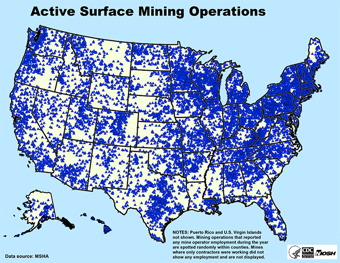
The most recently available data shows that we have over 13,000 mines in the U.S. By law, all mines must be registered with the U.S. Mine Safety and Health Administration (MSHA), and by analyzing their database, we can learn much about mining in this country. For example, we can determine the number of mines by commodity, size, and location. Back to the question: where are these mines? They’re everywhere, and you probably didn’t realize it! Take a look at Figure 1.3.1 below, which shows the location of these mines by major sector, i.e., metal, nonmetal, and coal.
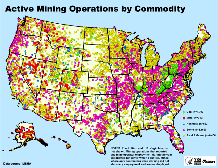
Before examining this map more closely, we should address the related question: why are they where they are? What do you think?
First and foremost, the availability of the mineral resource will dictate where we mine. Although minerals of nearly every variety are found through the crust of the Earth, it is relatively rare to find a concentration of a particular mineral to justify a commercial mining activity. Of course, the relative rarity of an economic concentration depends on the commodity. If we want to mine gold, for example, there are a limited number of locations where we will find economic concentrations. On the other hand, if we want to mine stone for construction purposes, we can find it almost anywhere.
Let’s say we know of an economic deposit. Are there are other factors that would determine whether or not we would open a mine at that location? Yes, absolutely there are, and we will look at that in more detail later in this course. For the purposes of this discussion, I’ll bring one additional consideration to your attention with the following example. Economic deposits of metals exist in the densely populated areas of the east coast. Decades ago, there were commercial metal mining activities, e.g., New Jersey Zinc Company. Today, there are none. Why? The land is so valuable that it would be prohibitively expensive to acquire it, and urban zoning ordinances severely restrict mining operations. Now, with this background, let’s take a closer look at the locations of these mines.
The metal and nonmetal mines encompass the nonfuel minerals. For reasons that may become clear as we go through this course, a variety of terms, which are similar if not synonymous, are used by geologists, mining engineers, and government regulators. Anyway, the location of the metal/nonmetal mines is shown in Figure 1.3.2.
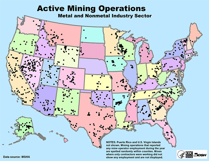
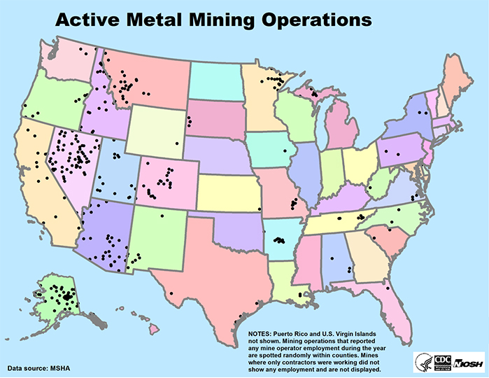
We can go down one additional level, and separate the metal from the nonmetal mines, as shown in Figures 1.3.3 and 1.3.4.
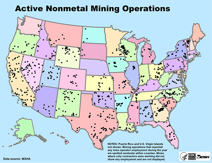
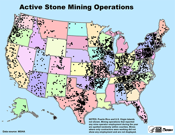
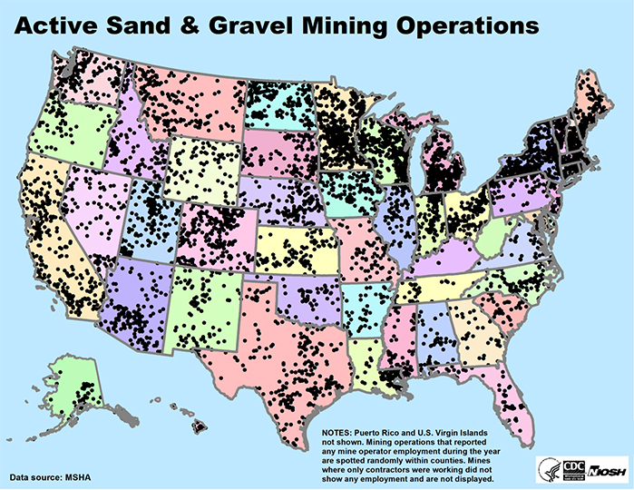
Stone, sand, and gravel mines are generally grouped together and are separated from metal/nonmetal mines even though these commodities qualify as nonmetal. For clarity, the stone mines are shown separately from the sand and gravel mines in Figures 1.3.5 and 1.3.6. As you can see, the number of mines is remarkably large. They are everywhere! Why are they everywhere? Simply, several different minerals can be used as aggregates, i.e., stone, sand, and gravel; and as such, they are readily found throughout the U.S. Just because we have a mineable deposit, do we have a need for a mine? No! What else do we need? There must be a demand for whatever we are going to mine, i.e., we need a market for the mined product. Aggregates are used for what purpose? The primary use is in construction – construction of houses, buildings, roads, and so on. Thus there is a strong demand for aggregates wherever people live and work, and this is evident from the maps.
1.3.1: Where Are All of These Mines? Continued
1.3.1: Where Are All of These Mines? Continued
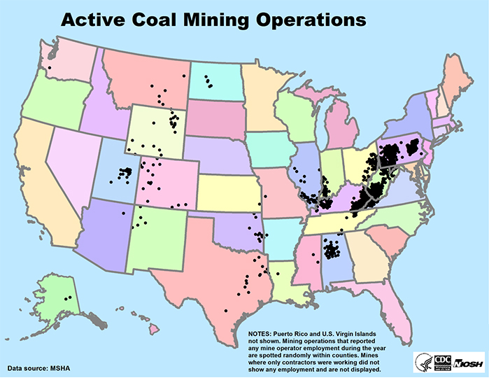
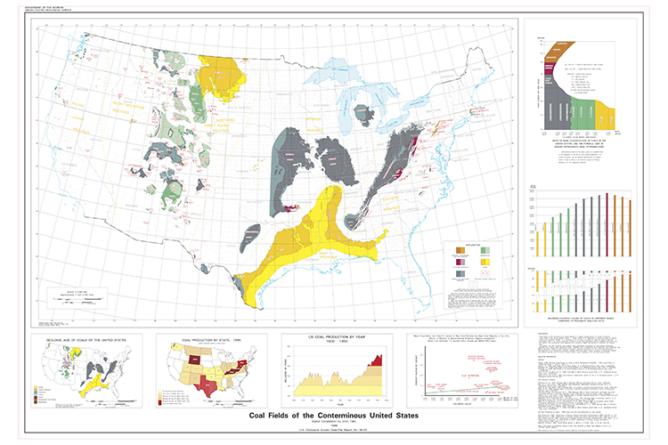
Next, let’s look at the fuel minerals, and specifically coal. After looking at Figure 1.3.7, examine the USGS map of U.S. coalfields in Figure 1.3.8. Do you see the correspondence between the coalfields and the location of coal mines? There is a lot of detail to be gleaned from this figure, and I suggest you zoom in and take a closer look. Take note of the rank of the coal found in the different coalfields, and also note the relatively few locations in which metallurgical-grade coal is found.
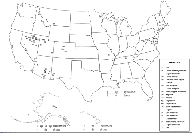
These figures that we’ve just examined are helpful as we endeavor to learn major characteristics of the U.S. mining industry. There are many ways to “slice and dice” the available data, depending on your specific interests. In this lesson, I want to look at a few additional representations. The first is to break out in more detail the major metal and nonmetal (industrial mineral) mining regions by commodity. Figure 1.3.9 details the locations of 15 metal commodities. Note that in many cases each commodity label represents multiple mines in that location.
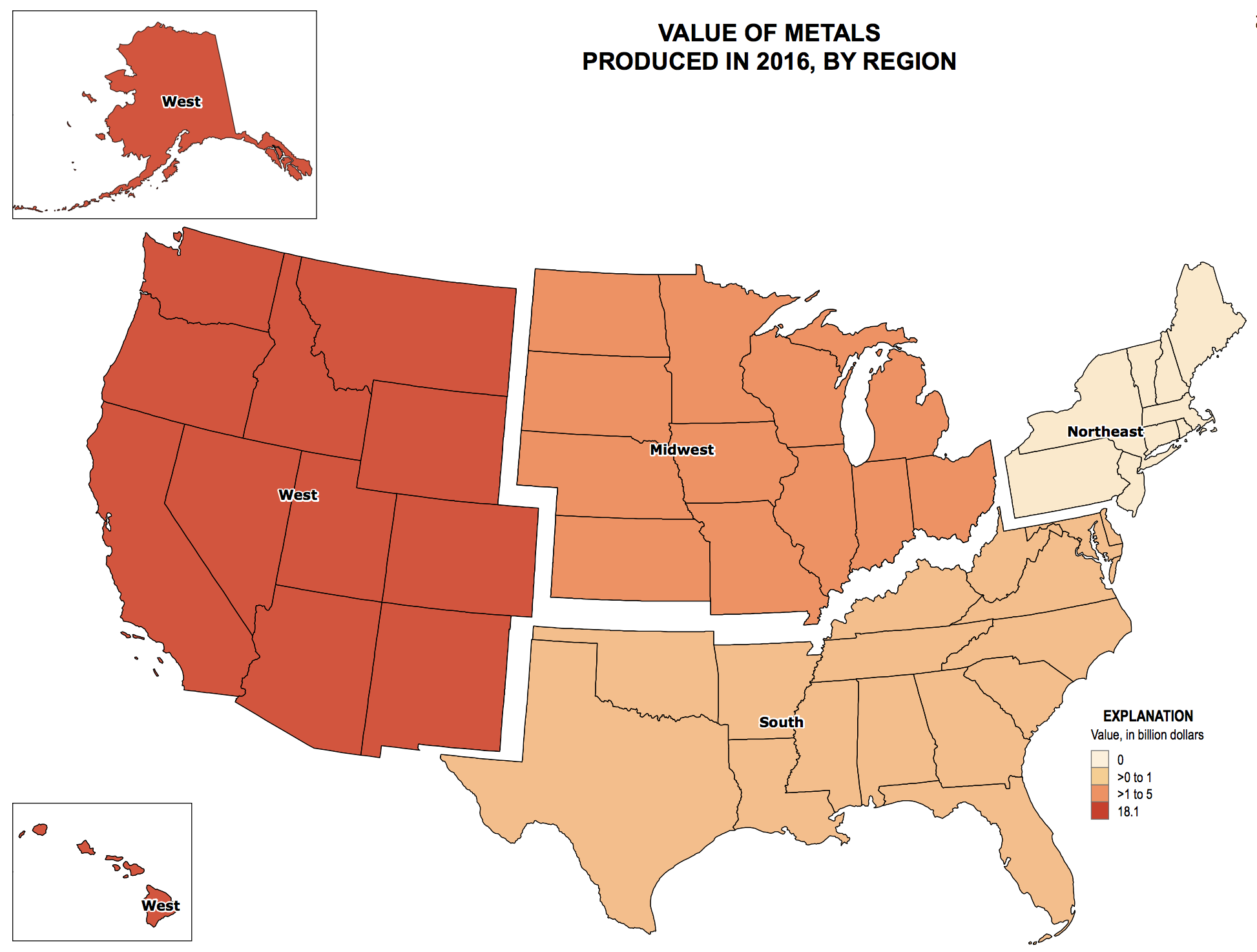
The second representation that I want to introduce here is the relative economic value or significance of mining in specific regions. The economic value of metals mined in the U.S. is shown by region in Figure 1.3.10.
We can examine industrial minerals in the same fashion, starting this time with the economic value of industrial minerals production by state, as shown in Figure 1.3.11.

1.3.2: Where Are All of These Mines? Continued
1.3.2: Where Are All of These Mines? Continued
Then, we can then go to a more detailed commodity map to see not only the location at which the major industrial minerals are mined, but also which ones are contributing to the economic value within a given state or region. Figures 1.3.12 and 1.3.13 show the location of industrial mineral mines for approximately 40 different commodities.
Figure 1.3.12 - USCS Mineral Commodity Summaries, 2017 [13] page 13
Figure 1.3.13 - USCS Mineral Commodity Summaries, 2017 [13] page 14
Without belaboring the point, we should look at the stone, sand, and gravel sector. Figures 1.3.14 illustrates both the value by state, and the location of the stone mines within each state, and Figure 1.3.15 does the same for sand and gravel operations. As before, the individual tags or in this case “dots” often represent several mines.

Figure 1.3.14 - USCS Mineral Commodity Summaries, 2017 [13] page 19
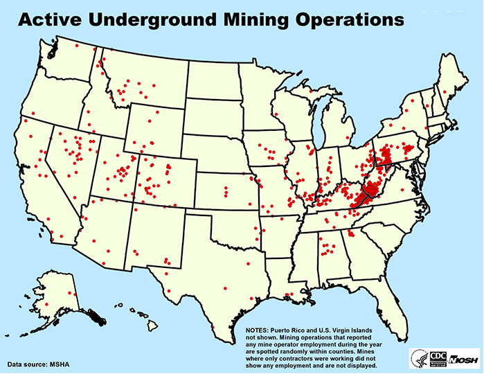
Finally, I would close this discussion that has focused on the location of mining activity with a different perspective on the location of mines. We now understand the geographic dispersion of mining activity as well as the concentration of mining in certain areas for certain commodities. A different twist to the question, where are these mines?, is: are these mines located on the surface or are they deep beneath the surface? Figures 1.3.16 and 1.3.17 clearly show that most mining occurs in surface rather than underground mines, by a ratio of nearly 15:1. We’ll examine the reasons for this later in the course, but an important point now is that most of these mines are located on the surface.
In this lesson we’ve learned where the fuel and nonfuel minerals are mined, and we’ve developed a better understanding of the extent of mining activities. Soon, we will be ready to look at the life cycle of mining operations and the engineering associated with each part of the cycle. Prior to doing so, there is one last overarching topic to cover, and that is mining in today’s world.
Lesson 1.4: Mining in Contemporary Society
Lesson 1.4: Mining in Contemporary Society
Once upon a time, a mining operation was opened with little more than a mule, a pickaxe, a shovel, and some camping supplies, and of course a crusty old guy with a floppy hat! Alas, the world has become much more complicated, and opening and operating a mine has become a complex undertaking. In the early stages, the mining engineers may well be part of a team consisting of professionals from archeologists to zoologists! Really, I am not joking! Before we delve into the details of designing and operating mines, we’ll be well served with a basic understanding of the broad context in which mining occurs today, i.e., the interactions between the mine or mining company and other elements of society. Let’s start with that piece in this lesson.
The diagram that we constructed in this lesson captures the workings of real-world mining; and for those of you who will work in this industry in an engineering or science capacity, you will experience many of these interactions very early in your career and throughout your career. Moreover, an understanding of the societal context in which mining occurs will help you to understand why we follow certain practices, or why we are limited in our approaches. Beyond that, this lesson has served as platform to introduce you to key stakeholders in the mining industry. A mining stakeholder is a person or organization that either affects the mining operation or can be affected by the mining operation. Given our discussion here, I think you will agree that the organizations represented in our diagram are very important stakeholders. If we were to attempt a list of all stakeholders, it would be very long and include manufacturers, universities, consultants, contractors, and on and on. Arguably there is one significant stakeholder missing from the diagram: Non-Governmental Organizations, known as NGOs. An NGO is an organization that is independent of governments, is funded through donations, and has a specific mission, e.g., protect the environment. In particular, there are many NGOs at the regional, national, and international level with missions that are in conflict with mining. For example, some NGOs operate on the belief that there should be no extraction of resources for any purpose, while others have a primary interest of ensuring no damage to the environment. Others seek the elimination of fossil fuel usage. Regardless of your politics and beliefs, NGOs are a reality. Through often-frivolous lawsuits, and civil disobedience that borders on or crosses over into criminal behavior, NGOs are important stakeholders in mining. The solution to this represents one of the grand challenges that will be discussed in this course.
Module 1 Summary
Module 1 Summary
An important goal of this module has been to give you a broad background on mining and the mining industry -- why we mine, the kinds of things we mine, where we mine, and the stakeholder groups with an interest in what we do. A general understanding of the many mined commodities, their use and importance, and the locations where these minerals are found will be helpful as we begin to study the life cycle of a mine. Similarly, the influence of the stakeholders permeates many of the processes in the stages of the life cycle, and with knowledge of these stakeholders and their role, you will understand better why we do certain things in ways that might not be entirely obvious! Moreover, you will interact on a regular basis with many of the stakeholders that you learned about, and the more you understand of their role, the more effective you will be in your job.
More Matt B. Practice Questions:
Practice
Lesson Roadmap
| To Read |
SECS, Chapter 16: Project Design SECS, Ch 9: Solar Economics (selected sections) S. Stoft (2002) Power System Economics, Designing Markets for Electricity, IEEE Press & WILEY-INTERSCIENCE, 2002 (pp. 30-48). N. Pfund and B. Healey. (2011) What would Jefferson do? The historical role of federal subsidies in shaping America’s energy future. Technical report, DBL Investors. (PDF available on DBL Site [14]) |
Textbook |
|---|---|---|
| To Read (Optional) |
M. Lave and J. Kleissl. (2011) Optimum fixed orientations and benefits of tracking for capturing solar radiation in the continental United States. Renewable Energy, 36:1145–1152. C. B. Christensen and G. M. Barker (2001) Effects of tilt and azimuth on annual incident solar radiation for United States locations. In: Proceedings of Solar Forum 2001: Solar Energy: The Power to Choose, April 21-25 2001 T. Huld, M. Šúri, T. Cebecauer, E. D. Dunlop (2008) Comparison of electricity yield from fixed and sun-tracking PV systems in Europe. European Commission, Joint Research CentreInstitute for Energy, Renewable Energies Unit, via E. Fermi 2749, TP 450, I-21027 Ispra (VA), Italy (poster, PDF). |
??? |
| To Do: |
|
|
ractice
Overview
Regimes will show that time and space are related to meteorological phenomena using basic principles of Taylor's Hypothesis. We will describe how events in the future can be subject to resource analyses and (to certain degrees of confidence) prediction from historical knowledge and from the knowledge of present events that are connected spatially to the locale of interest. In particular, we are interested in tools used by meteorologists.
Electricity markets are inherently focused on user/client demand, and time-independent demands for electricity by any and all customers. This demand profile has patterns, yes, but it is less predictable than one might think (storms, pandemics, sunny days, heat waves, power outages, congestion, sporting events). Demand for electricity is variable, and the prices for electricity also vary with respect to the power congestion in the transmission grid. But we are combining two flow-based systems here: solar energy conversion systems are dynamic in their supply of electricity to markets. Thus there are two conjugate groupings of variability central to solar power markets operating on a transmission grid.
One of the key things about electricity converted from radiant shortwave energy is that solar irradiance drives the process of power generation. In contrast, fuel-based combustion conversion systems are more stock-constrained. Meaning a coal/gas-fired power plant or nuclear power plant will convert a source of AC power that will have low levels of variability (over the course of 15 min, say) compared to a small cumulus cloud passing overhead for a solar photovoltaic farm, blocking the beam component of light.
Both weather systems and demand on the grid (called loads) will be presented as dynamic, coupled parameters. Both weather and grid loads will deeply affect our clients in terms of the required decisions for solar technology deployment and management. Both will be shown to have a spread of possible outcomes for a given time horizon; and thus, there will be uncertainty and risk in making decisions.
Now, the point of Lesson 9 is to familiarize yourself with modern elements of phenomena that affect project risk assessment and management due to the dynamic behaviors of the grid and of the local weather systems, and the behaviors of people living within those local weather systems.
- Utility as preference, stakeholder as value holders (client, customer, investor), locale as place-time context constraining decisions
- Flow vs. Stock Energy Reserves
- Value and Quantity of Light as a Commodity
- Goal of Solar Design: Seeking out high stakeholder preference
Learning Outcomes
- Convey the three key criteria within the goal of solar design and engineering;
- List the three main engineering parameters of locale that will guide your design options;
- Describe the role of the power grid for decision making for photovoltaic strategies; and
- Use the economic constraints of the client to constrain your design options.
Lesson Roadmap
| To Read |
SECS, Chapter 16: Project Design SECS, Ch 9: Solar Economics (selected sections) S. Stoft (2002) Power System Economics, Designing Markets for Electricity, IEEE Press & WILEY-INTERSCIENCE, 2002 (pp. 30-48). N. Pfund and B. Healey. (2011) What would Jefferson do? The historical role of federal subsidies in shaping America’s energy future. Technical report, DBL Investors. (PDF available on DBL Site [14]) |
Textbook |
|---|---|---|
| To Read (Optional) |
M. Lave and J. Kleissl. (2011) Optimum fixed orientations and benefits of tracking for capturing solar radiation in the continental United States. Renewable Energy, 36:1145–1152. C. B. Christensen and G. M. Barker (2001) Effects of tilt and azimuth on annual incident solar radiation for United States locations. In: Proceedings of Solar Forum 2001: Solar Energy: The Power to Choose, April 21-25 2001 T. Huld, M. Šúri, T. Cebecauer, E. D. Dunlop (2008) Comparison of electricity yield from fixed and sun-tracking PV systems in Europe. European Commission, Joint Research CentreInstitute for Energy, Renewable Energies Unit, via E. Fermi 2749, TP 450, I-21027 Ispra (VA), Italy (poster, PDF). |
??? |
| To Do: |
|
|
Questions?
If you have any questions, please send us a message. We will check daily to respond, with the exception of weekends. If your question is one that is relevant to the entire class, we may respond to the entire class rather than individually.
Module 2: The Life Cycle of a Mine and Related Matters
Module 2 Overview
Module 2 Overview
We learned a lot… actually, I hope you’ve learned a lot about the importance of minerals and the need for mining in Module 1. We now have a much better understanding of where we mine and why we mine. We have learned about the complexity of conducting a mining operation in a societal context. The study of this has allowed us to gain not only an appreciation for the complexity of operation in today’s world, but it has also given us a reason to learn more about the major stakeholders. We will draw on much of this recently acquired knowledge throughout this course.
So, we know a lot the importance of minerals in modern society, we better understand how ubiquitous mining is in the national and global economies, and we know about the important stakeholders. Suppose we want to mine one of those 85+ minerals found in economic quantities within the U.S. How do you go about opening and operating a mine? We’ll first address this topic in Lesson 2.1, where we will examine the life cycle of a mine. In Lessons 2.2 and 2.3, we’ll look at the body of laws that apply to particular parts or throughout the life cycle of the mine. Equipped with this knowledge, as well as that of Module 1, we will then devote the remainder of the course to the specific details of surface and underground mining.
Learning Outcomes
At the successful completion of this module, you should be able to:
- describe each of the five stages in the life of a mine;
- explain the difference between an Act (law) and a Regulation;
- explain the purpose of the Code of Federal Regulations, and Title 30, Volume I, Chapter I of the Code of Federal Regulations;
- list and describe the five major categories of mining law that govern everything from access to minerals, how we mine, to how we leave the site when we have finished mining;
- cite specific examples of laws that the mining engineer will encounter within the aforementioned categories;
- describe the differences in the acquisition of rights to prospect, explore, and mine on public and private lands;
- describe the General Mining Law of 1872, and specifically explain:
- the stated purpose of the Law,
- a mining claim, and the difference between a lode and a placer,
- what is meant by locatable minerals, and the types of minerals that qualified under the Law,
- the difference between a patented and unpatented claim;
- explain the motivation behind the Mineral Leasing Act of 1920, and the change that this Act made to the Mining Law of 1872;
- explain the effect of three other major amendments to the Law of 1872, made in 1954, 1955, and 1976;
- explain why the Law of 1872 remains controversial to this day.
Lesson 2.1: Life Cycle of Mines
Lesson 2.1: Life Cycle of Mines
Modern mining occurs over five stages, which constitute the life cycle of a mine. They are listed here and are summarized in the following paragraphs.
- Prospecting
- Exploration
- Development
- Exploitation
- Reclamation
While the principal activities of each stage are distinct, there can be significant overlap in the tasks comprising the stages as well as the professionals active in the stages.
Prospecting
The crust of the Earth is made of rocks and minerals, and many minerals can be found with little difficulty. In general, the challenge is not finding the mineral of interest; but rather finding an economic concentration of the mineral. Despite the fact that minerals are everywhere, it is a rarity to find most of them in sufficient concentration to justify the cost of developing a mine and extracting the mineral of interest. In most instances, prospecting is about finding geologic anomalies! The professionals that lead this first stage of the life cycle are geoscientists, e.g., geologists, geochemists, and geophysicists.
Geologists often narrow their search by taking advantage of accumulated knowledge, which may be public or proprietary, to narrow the geographic scope of their search. They may use satellite images or aerial mapping techniques as they search for promising indicators. Then the search will continue with on-the-ground investigation using surface-mapping, structural analysis, and other scientific techniques. In many cases, the expertise of geochemists and geophysicists may be required to help in the discovery of an orebody, i.e., a potentially economic concentration of the target mineral(s). Geochemists may glean vital clues by analyzing water or soil samples, for example; and geophysicists may use instruments to detect subtle and localized changes in the electrical or magnetic field, or they may map rock layers deep under the surface using seismic methods.
The goal of this team of geoscientists, and indeed the goal of prospecting, is to discover a concentration of the target mineral that has the potential to be mined at a profit. What do you think determines if it has the potential to be mined at a profit?
While there are many factors that will be considered, there are only a few that are germane at this stage. Those few would include the size and grade of the orebody. If the outcome of the prospecting stage is evidence supporting the presence of an orebody of sufficient size and grade to justify mining, then work will begin on the second stage, known as exploration. The prospecting stage may have cost tens of thousands to millions of dollars. The next stage may be even more expensive, and is only undertaken if there is sufficient evidence to suggest an economic deposit of the target mineral(s).
Exploration
The next stage, exploration, will involve mining engineers as well as geoscientists who were involved in the prospecting stage. The goal of exploration is to define more exactly the size of the orebody, the grade, and the spatial and geotechnical characteristics of the deposit and surrounding rock. I think it is useful to think about exploration as a problem in risk management.
What is the risk that we need to manage? Simply, the risk is that we would spend millions of dollars to develop a mine, only to find that we can’t mine the deposit economically. How could we find ourselves in such a job-ending predicament? Perhaps the size of the deposit is far less than we estimated, or the grade is much poorer than we believed, or maybe there are large areas where the ore disappears or where there are intrusions of unwanted material, or features that make it difficult to extract, and so on. You get the idea – you need to be a good risk manager!
If you are the one to make the decision, to go forward or abandon the project, what can you do to manage your risk? You can seek to obtain as much information as possible about the deposit, although information acquisition comes at a price. It costs money to conduct more studies to learn more about the deposit. How much are you willing to spend? How badly do you want that information? Well, that depends on how much risk you are willing to accept. Hence, the concept of, and need for, risk management. As we continue through this lesson and this course, you will begin to develop a sense for managing the risk associated with these projects.
Our first significant encounter with risk management is in the exploration stage, and our first interest will be to estimate the size of the reserve, i.e., how many tons exist than can be recovered, and the quality of the reserve, i.e., what percentage of the recoverable tons contain the target mineral(s). This first task is known as reserve estimation, and consists of two parts: estimating the quantity and quality of the orebody; and determining how much of that orebody can be recovered utilizing currently available mining practices. Estimating the quantity and quality of the resource requires sampling, usually by drilling, and then analyzing the sampled material. Generally, the more samples that we take, the more certain we can be in our estimates of the quantity and quality of the resource. In other words, the more we sample, the more we reduce the risk of bad outcome. And of course, it costs money to acquire each sample!
However, it is not only about the quantity and quality of the resource. We could have a resource of high quality and enormous size. But that alone is insufficient. We have to be able to extract this resource economically from the earth. This is not always doable, or more likely, it is doable for some but not all of the resource. The technical reasons for this are varied, but during the exploration phase, the team will be interested in far more than simply the size of the resource. They will employ methods to estimate the strength of the rock surrounding the orebody as well as the strength of the ore itself. They will look for geological discontinuities and other features that will affect the extraction of the ore. Investors in an expensive mining project are far more interested in how much ore can be mined, processed, and sold, than how much ore is in the ground! We’ll look at this in more detail in Module 3 when we talk about resource and reserve estimation.
There is one of two likely outcomes from the exploration stage: a decision to continue development on a project that appears promising or a decision to abandon the project. If the decision is to move forward with the project, then work will advance to the development stage.
Development
Essentially, the development stage includes all of the activities necessary to prepare for extraction of the ore. These activities begin with the engineering studies that immediately follow the exploration stage through the construction of the physical plant to access and process the ore. In the case of a surface mine, the development work to access the orebody may consist of removing vegetation and the overburden, which covers the orebody; whereas in the case of an underground mine, the development work will conclude with the construction of the shaft or other means of connecting the surface with the orebody that is located some distance beneath the surface.
A significant amount of capital must be available to open a mine. In many cases, this money must be raised from investors, and on some cases the company will have the capital to invest in the project. In either case, additional engineering studies will be conducted to establish the feasibility of opening a mine. A company with its own capital, will have many competing projects for that money, and they will want to allocate it to the project that best meets their criteria for a return on their capital. Investors on the other hand, will also want to understand the income potential of their investment. And in either scenario, both will want to understand the risks associated with the project. In Module 4 we will look at the engineering studies that are performed to address these concerns. For now, you should be aware that a prefeasibility study is nearly always conducted as the first task in this stage; and that the requirements for conducting and reporting on this prefeasibility study are prescribed by legal documents and are regulated by various government agencies around the globe. It is a requirement that these studies, completed according to the applicable standard, be published as part of an effort to raise funds for the project on any of the stock exchanges.
The selection of the mining method will be made during the prefeasibility study, as this is an essential consideration when determining how much of the in-place resource can be extracted. The selection is based on an evaluation of several factors that we will examine in Module 4; often the choice of a method will be guided by the practices found in other mines in the region that are mining some the same commodities.
The prefeasibility study will determine in most cases whether or not a viable project exists. If so, the development work will continue. Rights to the land and the deposit will be acquired, detailed engineering studies will be completed, bid packages will be prepared, and construction will begin on surface facilities, such as offices and labs, warehouses, shops, and the mineral processing plant, among others. Land clearing and other surface infrastructure construction, including roads, electric power, water, and so on will be ongoing during the development stage. As described previously, the development stage is largely completed with those tasks that allow direct access to the orebody. Once the orebody has been made accessible, the extraction process can begin.
Exploitation
One definition of this word, according to the dictionary, is the process of making the fullest and most profitable use of a natural resource. Indeed, the process of extracting the ore from the surrounding rock and processing it to make the valuable components available to society is the goal of the exploitation stage. Essentially, this stage consists of the extraction activities, in which we remove the ore and move it to a plant for the beneficiation activities, in which we separate and concentrate the valuable minerals from the run-of-mine materials coming from the mine and going into the mineral processing (beneficiation) plant. An important concern is the handling and disposal of these tailings, which remain after the valuable components have been removed. We will say little about the mineral processing other than these two points: the design and operation of mineral processing is beyond the scope of this course; and the mining engineer, in the selection and use of a particular mining method, along with the associated unit operations, can impact significantly the cost of the mineral processing operation. We will concern ourselves with the latter point, when we talk about the selection of the mining method and some of the unit operations.
The mining method will have been chosen well before exploitation begins, although the method may be altered or occasionally changed if conditions change significantly. Over time the equipment and practices may be changed to achieve economic, environmental, or safety goals. After all, many mines will be in the exploitation stage for several decades, and during this time the available mining technology and state-of-the-art practices will certainly change, even if mining conditions at the mine have not changed significantly from the day that the mine was opened. It is not unusual to find mines that began as surface mines, and then after the resource could no longer be recovered economically by surface mining, an underground mine was developed.
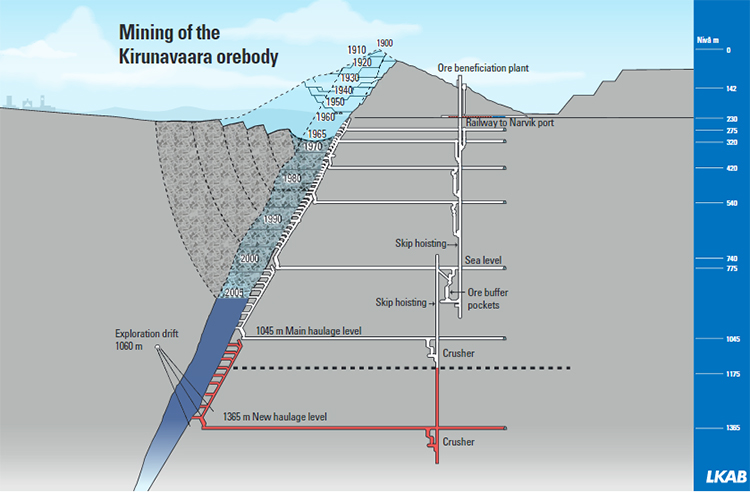
Mining of the Kirunavaara iron orebody in Kiruna, Sweden is a famous example of this, and as you will note in the Figure 2.1.1, below, that mining began in 1900 as a surface mining operation, and continued as such for 65 years. At that point in time, the cost of removing the overburden to access the ore became greater than the value of the ore that was being uncovered. This is known as the breakeven stripping ratio, and when this ultimate pit limit has been reached, mining will stop or alternatively, an underground mine will be developed; and that is what happened at this mine. Nearly 125 years after the initial mining, the mine still has many years of life remaining.
Whether it is in five, fifty, or five-hundred years, the exploitation stage will come to an end. The orebody for which the company has the rights to mine may have been exhausted, it may be uneconomical to continue mining, or the perhaps the market for the commodity no longer exists. Regardless of the cause, at the conclusion of active mining, the company cannot simply “walk away” from the operation; although well into the beginning of the 20th century that was the common practice. That irresponsible practice has left us with a legacy of abandoned mines, numbering in the thousands. Even though most of these were very small operations, some were large, and regardless of their size, many of them present public safety and environmental hazards. There may be, for example, shafts that hikers could unwittingly fall into, pollutants draining from old workings, or unsightly piles of tailings. This is a serious issue for society, and it is a major reason why mining has a negative public image.
The conclusion of active mining signals the beginning of the fifth and final stage in the mine’s life cycle, known as reclamation.
Reclamation
The goal of this final stage is to return the mine site to its original condition. In the case of an underground mine, we can do that rather completely. In the case of a surface mine, we cannot in many cases return it to original condition because so much material will have been removed and sold. However, we can take steps to ensure that the area is reclaimed to be free of safety and environmental hazards in all cases, and that the end result is aesthetically pleasing in many cases. The latter is simply impossible in the case of large open pit mines, as the volume of material removed over the years is so large that the remaining pit dimensions cannot be covered over. The number of these operations is a very small fraction of all surface mines, and the majority of these are located in rather remote and rugged areas. However, to be clear, even in those cases, the obligation to leave an area free of safety and environmental hazards is unchanged.
Overall, and during the reclamation stage, it will be necessary to remove completely all of the surface physical plant, e.g., buildings, power lines, and so on. Returning the land to original contours and/or ensuring that options for land use after mining are as good or better than the use prior to mining is important. This work may include grading and revegetation, among other steps. In most cases, the final outcome of the reclamation stage is a site on which the land is once again available for public or private use, free of hazards, and often more attractive and useful than prior to mining.
Of course, it is not just left to the social conscience of the company to ensure that reclamation is completed: there are laws, regulations, and multiple government agencies to ensure that the reclamation is completed. In fact, you will have to prepare and submit your plan for reclamation before you have started mining. And, in virtually all cases, you will have to put up a bond to ensure that the reclamation can be completed, even if you go out of business before the site has been fully reclaimed. These bonds are funded at a level to ensure that the work can be completed if the company defaults on its obligation. The cost of bonds can run into the millions of dollars very quickly, and the money is not returned to the company until the work covered by that bond is completed and approved by the government agency. In some cases, a company may need to operate a water treatment plant in perpetuity to ensure, for example, that groundwater drainage from an abandoned underground mine does not pollute the local streams. In such a case, the company will be required to post a bond of sufficient value that the government could continue to operate the plant if the company should go out of business.
Such planning and actions are consistent with the 21st century goal of sustainability. Whether we’re meeting humankind’s need for food or minerals, for example, we have a societal obligation to do so in a sustainable manner. This is generally accepted to mean that in meeting our current needs, we will use practices that will not compromise future generations’ ability to meet their needs. Further, it is implied that these practices will not compromise the environment nor the health of future generations. Sustainable practices are based on recognition that resources are finite. Consequently, we design mines to maximize the extraction ratio so that we can meet our production goals while disturbing as little of the resource as possible. In contrast, years ago, some mines might only recover less than half of the in-place reserve, but in the process, they would “sterilize” the remaining resource, i.e., the remaining resource could not be safely recovered in the future because of the way that the previous mining was conducted.
The five stages of a mine’s life cycle as presented in this lesson are a convenient way to describe the sequence of activities that define a modern mining operation. As you have no doubt realized, the boundary between each stage is not as crisp as this lesson might have implied. Not only is there overlap, but also at different times and in different places, parts of the cycle may repeat. For example, as the exploitation of a deep metal mine continues, new exploration activities will be initiated, but not from the surface. Instead, they will be conducted deep within the mine, where the geologists have a “front row seat” to observe and characterize the orebody in greater detail.
In the next lesson, we’ll look at the body of laws that apply to these stages of mining.
Test your knowledge!
Lesson 2.2: Mining Law
Lesson 2.2: Mining Law
The body of law governing access to minerals, the rights to mine, and the conditions under which mining is conducted and concluded is vast. Some laws apply primarily to the earliest part of the cycle, i.e., prospecting and exploration, whereas others are more relevant to the end stage of the cycle, i.e., reclamation. The majority will apply through all stages. In total, the number of laws that impact a mining operation number in the hundreds, and fortunately there are many lawyers who choose to specialize and practice in mining law! Still, there are some laws that directly impact the work of the engineers and scientists who are working in the various stages of the mine’s life cycle; and further, some of these laws are very technical in nature, and the mining engineer and other professionals will require sufficient knowledge of them to complete their work. Accordingly, a goal of this lesson is to build a foundation of knowledge for your future work.
Laws can be national (federal) or regional (state or local) in origin. Certain aspects of a mining operation could be subject to international agreement, as well; although this topic is beyond the scope of this lesson. It should be noted that the multinational mining companies typically adhere to the most rigorous set of laws and standardize their operations to be in compliance with those. The “home” country of the multinational may have laws that govern the activity of the corporation even when those activities are in another country. Again, this is a topic well beyond the scope of this course.
It is important to remember the laws and regulations are not the same, even though in many cases the outcome is indistinguishable. Congress or committees of Congress, develop bills, and upon passage by both the Senate and the House of Representatives, the act, as it is then known, goes to the President for signature. If the president signs the bill, it becomes law. The law may have specific provisions with which the mining company must comply, or face civil or criminal proceedings. Often the law also directs an administrative agency, such as MSHA or the EPA, to develop regulations that will accomplish Congress’ intent in passing the legislation. The agency will write specific and often very prescriptive regulations. The mine operators are then legally bound to comply with those regulations, or face a range of civil or possibly criminal actions. Typically, a violation of mandatory regulation results in a fine of tens of dollars up to hundreds-of-thousands of dollars depending on defined criteria, which include the severity of the violation. It can also result in a closure of the mine until the violation is corrected, and in a few cases, criminal charges may be pressed.
Here is an example of an Act. If you note the last sentence on the page, you'll see the language directing the agencies to develop and promulgate regulations.
FEDERAL MINE SAFETY AND HEALTH ACT OF 1977
[Public Law 91–173]
[As Amended Through P.L. 109–280, Enacted August 17, 2006]
AN ACT To provide for the protection of the health and safety of persons working in the coal mining industry of the United States, and for other purposes.
Be it enacted by the Senate and House of Representatives of the United States of America in Congress assembled,
That this Act may be cited as the “Federal Mine Safety and Health Act of 1977”.
(30 U.S.C. 801 nt) Enacted December30,1969, P.L, 91–173,sec.1,83 Stat. 742; amended November 9, 1977, P.L. 95–164, title I, sec. 101, 91 Stat. 1290.
FINDINGS AND PURPOSE
SEC. 2. Congress declares that—
(a) the first priority and concern of all in the coal or other mining industry must be the health and safety of its most precious resource -- the miner;
(b) deaths and serious injuries from unsafe and unhealthful conditions and practices in the coal or other mines cause grief and suffering to the miners and to their families;
(c) there is an urgent need to provide more effective means and measures for improving the working conditions and practices in the Nation’s coal or other mines in order to prevent death and serious physical harm, and in order to prevent occupational diseases originating in such mines;
(d) the existence of unsafe and unhealthful conditions and practices in the Nation’s coal or other mines is a serious impediment to the future growth of the coal or other mining industry and cannot be tolerated;
(e) the operators of such mines with the assistance of the miners have the primary responsibility to prevent the existence of such conditions and practices in such mines;
(f) the disruption of production and the loss of income to operators and miners as a result of coal or other mine accidents or occupationally caused diseases unduly impedes and burdens commerce; and
(g) it is the purpose of this Act (1) to establish interim mandatory health and safety standards and to direct the Secretary of Health, Education, and Welfare1and the Secretary of Labor to develop and promulgate improved mandatory
1References in this Act to the Secretary of Health, Education, and Welfare are deemed to refer to the Secretary of Health and Human Services pursuant to section 509(b) of the Department of Education Organization Act (20 U.S.C. 3508(b); 93 Stat. 695).
The regulations developed by an administrative agency are compiled in the Code of Federal Regulations (CFR), which consists of 50 Titles. The list of Titles can be found on the website of the U.S. Government Publishing Office or other sites including Wikipedia. For completeness, we can note that laws are codified in the United States Code (USC), which is also organized by Titles.
Regulations relating to mineral resources are found in Title 30 “Mineral Resources” and many of the regulations affecting the environment are found in Title 40 “Protection of Environment.” Looking more closely at Title 30, you will see that it is divided into volumes, chapters, and parts. Within Title 30, the most applicable content for us is found in Chapter I, which contains the regulations on mine safety and health promulgated by the MSHA. You can download a pdf file of any of these Titles, and I recommend that you download Title 30 Volume 1.
Here is an example from Title 30 to illustrate specific regulations.
If we wanted to cite a specific regulation, for example the one on the separation of stored explosive material, we would write it 30CFR 57.6100.
The regulatory environment has become so complex and pervasive, that even entry-level engineers and scientists will be drawn into conversations regarding requirements of the Mine Act (a law) and regulations. Consequently, it is helpful to understand these terms and where you can go to read them.
With the distinction between laws and regulations behind us, let’s return to our overview of mining law.
First, we can categorize the body of law into five groups for our purposes, as follows:
- access to the land, including the right to mine
- taxes, leasing fees, royalties
- employment, work conditions, and compensation
- environmental protection
- cultural and social issues
Let’s examine each of these in more detail.
Access to the Land, including the Right to Mine
We need access to the land to conduct prospecting and exploration activities, and if we decide to mine, we will need to obtain permission to extract the commodity. Acquisition of these rights is obtained differently on private versus public land. I think we all have an understanding of private land, i.e., land owned by an individual or legal entity such as a company or a trust. Rights to access and mine private property are conveyed simply by an agreement, such as a contract, a lease, or a deed.
What about public land?
All land that was part of the original 13 colonies that became the United States was privately owned. After the birth of the Nation, the U.S. government acquired blocks of land, and that land belonged to the government, i.e., the “public.” Over the years and through different programs, some of that land became privately owned, although vast tracts of public land still exist to this day. In the American West, the government owns nearly half of the land; and in Nevada, for example, the U.S. government owns about 80%. In total, the government owns a third of America! Thus, acquisition of the rights to prospect, explore, and mine on public lands must be completed in compliance with the applicable laws.
The Mining Law of 1872, as amended, governs access to public land for the purpose of prospecting, exploration, and mining. The Bureau of Land Management administers this law within the Department of the Interior. Due to its importance, we are going to discuss this law as a separate topic later in this lesson.
Before moving on to the next category of mining law, I want to make a few more comments regarding the rights acquired on private land. There are many rights that may or may not be transferred in the agreement. For example, if you acquire the right to mine a salt deposit deep below the surface of the Earth, are you entitled to cut and sell the timber on the surface above your underground mine? Likely the answer is: only if you acquired the timber rights as well. What about surface rights above your mine? Can you build a warehouse, shop, or mineral processing plant on the surface? Likely, the answer is: only if you acquired the surface rights for that tract of land. What about the mineral rights themselves? Did you, through your agreement with the private owner acquire the right to mine all minerals or only one?
Suppose that you have obtained the right to surface mine coal. In the process of removing the overlying materials to access the coal bed, you encounter a bed of limestone, for which there is a strong local market. Can you remove the limestone to access the coal? Absolutely. Can you sell the limestone? Maybe not! It depends on how the deed or contract transferred the mineral rights. Let’s look at one last example, which has been the subject of litigation over the years.
You’ve acquired the right to deep (underground) mine a coal seam. The coal has several hundred cubic feet of methane adsorbed for each ton of in-place coal. Modern mining practice would be to “drain” much of this gas prior to mining to lessen the likelihood of a gas explosion during mining. Can you vent the gas to the atmosphere as part of your pre-mining of the seam? Yes. Can you capture and sell the gas? Again, only if you also acquired the rights to the gas!
Over the years, landowners may have sold off some or all of their mineral rights. A company looking at their future interests may go into an area and buy-up the rights to particular minerals. Subsequently, when the landowner sells the land, the deed may exclude certain commodities. Oil and gas rights are commonly split off from the other mineral rights.
Thus, in the acquisition of rights on private land, it is important to know fully which mineral rights are being acquired, e.g. all those to a certain depth, all minerals, or only named minerals; and whether or not the land owner still owns the specific rights that are the subject of the acquisition.
Taxes, Bonds, Leasing Fees, and Royalties
There are several applicable laws and it's well beyond the mining engineer’s responsibility to know and apply them. Notwithstanding, it is important to be aware that the resulting costs are significant, and the mining engineer will include these in feasibility studies. For example, the following costs must be computed and included in analysis of feasibility, i.e., whether or not an economic mining operation can be developed:
- Federal, state, local income taxes, and severance taxes
- Royalties and leasing fees – upfront or as incurred, or both
- Depletion allowance
- Bonds
Typically, the engineering team estimates these values during the feasibility phase of project development. Once the mine is operational, the calculation of these, among others, will be turned over to the accountants and lawyers.
Employment, work conditions, compensation
There are a few hundred applicable laws ranging from Equal Employment Opportunity (EEO) to the Fair Labor Standards Act (FLSA) to the Family Medical Leave Act (FMLA), and most are beyond the scope of the mining engineer’s core activities. The mining company will typically have a human resources specialist or department, and will have standard operating policies to ensure that you do not run afoul of the law in your hiring, firing, and management of employees. If your mine site is unionized or there is interest in organizing, you will need to become knowledgeable on the current labor contract, or certain allowed and disallowed practices related to organizing activities. Workplace safety and health is treated as a condition of employment, and primarily this aligns with the Mine Act and MSHA regulations. These will affect significantly your mine design, planning, and operation.
Environmental Protection
There are many laws and resulting federal regulations to protect the environment. As with other categories of mining law, you as an engineer or scientist will not be practicing law in these areas, but you will be required to conduct engineering and scientific studies required by some of these laws, and you will need to be familiar with the compliance responsibilities in the mine design, operation, and closure phases. Here is a short list of laws that you are likely to encounter:
- Clean Air Act
- Clean Water Act
- Solid Waste Disposal Act
- Endangered Species Act
You may think of power plant or perhaps stack emissions, such as from a copper smelter when you hear about the Clean Air Act. And, you would be correct. What about the dust generated when a haul truck drives on a road within the surface mine, or what about the dust that the wind picks-up from storage pile of stone? These are examples of fugitive dust, and there are strict regulations governing these.
The Clean Water Act addresses not only such major pollutants as fertilizer runoff from agricultural activities, but virtually any other potential source. You will be required for example to prepare a storm water discharge management plan to address any water that may run off of your property during a rain storm and which may have sediment or any contaminant from your operation. Regulations from the same Act will require you to sample water discharges and install and maintain engineering controls to comply with the law.
The waste rock and minerals remaining after the ore has been processed to extract the valuable components are known as tailings. In some cases there may be few tailings, but in many cases, the tailings can account for 90% or more of the run-of-mine material that went into the plant. The Solid Waste Disposal Act will dictate not only the handling of municipal garbage, but also the handling of your tailings.
The Endangered Species Act aims to protect wildlife and their habitat, as well as to develop and administer plans to restore healthy populations of endangered species. Mine planning and operations must develop and execute plans to protect any endangered species that may be within their mine limit. Typically, this affects surface mines or the surface areas of underground mines. As an example, there may be a bird on the endangered species list that nests within the permit area of the mine. You would be required to propose and implement approved measures to ensure that ability of this bird to nest on your property would not be compromised to the detriment of the species. Depending on the area in which you intend to mine, the complexities could require that you retain a zoologist and perhaps other professionals to assist in preparing a plan to comply with the Endangered Species Act.
Sometimes needed and well-intended laws, like this Act, can be twisted for other purposes. I ran into a situation several years ago in which a citizens group was attempting to block a company from obtaining a permit to develop a surface mine, and their stated objection for blocking the permit was that a unique specie, found nowhere else, lived on the site; and that the mining activity would destroy that specie. The specie in question was a spider, and for some spiders, untold generations will live and die within an area of a few square meters. And over time, they will become genetically distinct – distinctions that require rigorous genetic study to identify. Ultimately it was determined that this spider did not qualify under the Act, and the U.S. Fish and Wildlife Commission signed off on the permit, but not without considerable delay to the project!
The Surface Mining Control and Reclamation Act of 1977 created the federal agency, Office of Surface Mining, Reclamation, and Enforcement (OSMRE) with a mandate to enforce reclamation activities at active coal mines, to operate a trust fund to reclaim abandoned mine lands. If you are operating a surface coal mine for example, you will have paid a bond to OSMRE, and your reclamation activities will be inspected to ensure they are consistent with the reclamation plan that you prepared for them. Commonly, the agency is referred to as OSM rather than the complete OSMRE.
Cultural and Social Issues
Two Acts of note in this category are the National Historic Preservation Act of 1966 and the Native American Graves Protection Act of 1990. Both are intended to protect and preserve historical and archeological sites. If there are any older structures on a proposed mine site, or if there is any suspicion that there could be items of archeological or cultural significance, a study will have to be completed; and if there are any, the structures, land, or items will have to be preserved. Often it is alleged that the proposed mining site falls under the protection of the aforementioned Acts. Typically, you would hire a consulting firm specializing in historical and cultural evaluation, and they would assign archaeologists to the project.
This concludes our overview of mining law as it intersects with the work of engineers on a mining project. In the next section, we’ll take a more detailed look at the General Mining Law of 1872 as amended.
Lesson 2.3: The General Mining Law of 1872 (as amended)
Lesson 2.3: The General Mining Law of 1872 (as amended)
We discussed the categories of laws that affect mining in the last lesson and took note of important examples of laws within those categories. Engineers working in the mining industry will often need a working knowledge of a few of these laws, particularly those related to mine safety & health, and the environment. The Mining Law of 1872, which is the subject of this lesson, applies primarily to the earliest stages of mining – obtaining the rights to prospect on public lands and then obtaining the rights to mine. It is considered a mandatory topic for mining engineers, and it is not unusual for a question on the P.E. exam to focus on this topic. It may surprise you to learn that the Law, as amended, is relevant today and quite controversial!
The General Mining Law of 1872 authorizes and governs the prospecting and mining for economic minerals on federal public lands, and the U. S. Bureau of Land Management (BLM) is the federal agency responsible for administering the Law.
The law has a rich and somewhat convoluted origin, having evolved from earlier legislation that was more about paying off war debts (Civil War) than fostering mineral development. All that aside, the Law was designed to codify orderly processes for acquiring and protecting mineral claims. The primary goal was to address the chaos and violence that was occurring in the mines and mining camps, particularly in Nevada and California. Prospectors and miners would fight over who had the rights to work a parcel of land. Miners from two different camps would be deep underground following a vein of gold, for example, when suddenly their underground workings would intersect. A dispute would quickly arise over who had the right to mine this vein, and such disputes were settled with guns, not lawyers! Thus, the primary goal of this federal law was to establish a set of uniform procedures to address these ambiguities.
A second unstated but likely goal was to promote settlement of the new lands in the West. As you will see, the Law gave options for outright ownership of land.
Over the years, there have been a few important amendments to the Law, and we’ll discuss those, but let’s start with the provisions of the original law first.
The salient elements of the Law are as follows.
All U. S. citizens 18 years of age or older have the right to locate a lode or placer claim on federal public lands that are open to mineral entry.
What does this mean?
- The first and last parts are easy: you have to be a U. S. citizen of a certain age to participate, and it applies only to federal public lands that are open to mineral entry. We know which lands are considered federal public lands from Lesson 2.2. A qualification that we didn’t make then, but need to make now, is that not all public land is open to mineral activity, i.e. mineral activity is prohibited on some federal public lands such as military bases and national parks. Ok, but what about the middle part –a lode or placer claim?
- At the time this law was written, there were two recognized types of mineral deposits: a lode, which is a hard rock vein, e. g. gold or silver; and a placer, which is a gold or silver-bearing sand or gravel, often in the form of a streambed.
The centerpiece of the law is the claim.
A mining claim is the right to explore for and extract minerals from a tract of land. The Law set the maximum size of a lode claim at 600 feet x 1500 feet, and the maximum size of a placer claim to be 20 acres. The Law also established a tunnel site, and this gave the holder rights to any lode found within 3000 feet of the entrance to the tunnel. Finally, the Law established mill sites, which cannot be on mineralized land, must be used for mineral processing, and can be up to 5 acres in size. There are a few other nuances and qualifiers to this, but the key points for you are to know are the definitions of claim, lode, and placer. There is no reason for you to remember the exact sizes of these claims.
The Law defined locatable minerals, i. e. the types of minerals that could be claimed under the law: gold, silver, cinnabar, copper, and other valuable deposits. The named minerals reflected the ones of note at the time the Law was written but also allowed for other valuable commodities to be claimed.
Extra-lateral rights allowed the owner of a claim with an outcrop to follow and mine that vein to wherever it led, including underneath other claims. This provision was also known as the law of the apex.
These mineral veins would often intersect the surface of the land, i.e. there would be an outcrop. It is likely that the vein would dip and go underground, and would continue for a considerable distance. This provision gives guidance on who has the right to mine the vein.
Claim staking is the required procedure of marking the boundaries of the claim and recording it; hence the expression “to stake a claim. ” The exact procedures for staking the claim may vary slightly from state to state.
All mining claims are initially unpatented claims and only give the right to explore and mine. These rights exist for as long as active work is underway each year. If active work ceases, the claim is dissolved and the land reverts back to the public domain. The Law defines active work on an annual basis as: at least $100 of labor shall be expended or $100 of improvements shall be made.
The Law defined a process by which the owner of a claim could patent the claim. Patents are deeds from the federal government for the claim. The holder of an unpatented claim can apply for a “patent” by making an application and paying $5 per acre for a lode claim or $2. 50 for a placer claim.
The owner of a patented claim can put the land to any legal use, and there is no requirement for active work on a patented claim. In other words, once the claim holder has a patent on the claim, the land can be used for farming, for building a house or a hotel, and so on. Literally, the land is owned (deeded) and can be used for any legal purpose! In more recent times, this provision of the Law has become controversial, but we’ll discuss that later.
The General Mining Law of 1872 worked well into the beginning of the 20th century when the Law effectively enabled a major oil rush in the West. You’ll recall that oil and natural gas are considered minerals, and they met the criteria of “other valuable minerals” under the Law. Tracts of land were being gobbled up so quickly that by 1909, President Taft intervened by executive order, withdrawing over three million acres of public lands. Ultimately, Congress crafted a permanent solution in the form of the Mineral Leasing Act of 1920.
This Act explicitly excluded certain minerals as “locatable” under the 1872 Law and required that the rights to these excluded minerals be obtained only by leasing. The minerals that can only be accessed through a lease are oil, natural gas, and other hydrocarbons, coal, phosphate, potassium, sodium, and sulfur.
The Mineral Leasing Act of 1920 and an amendment in 1947 specified the details of the leasing program, including the number of acres that can be leased, payments to the government, the lease period, and bidding procedures. These parameters are different for different minerals. The lease periods are typically 10 or 20 years, and there are provisions for renewals of 10 or 20 years. The payments to the government consist of three components:
- Bonus, which is paid upon award of the lease, and the normally the lease is awarded to the bidder who will pay the largest bonus;
- Rental, which is an annual charge of typically a few dollars per acre; and
- Royalty, which is a percentage of the gross value of the commodity, typically on the order of 10%.
Over the 30 years, there have been no less than 35 amendments to the Mineral Leasing Act, but the substantive points outlined here remain unchanged. Amendments and attempted amendments to this Act are ongoing for a couple of reasons. First, the revenue from the leases into the U. S. Treasury is significant, and mineral leases are an attractive target for legislators looking for new sources of revenue to fund spending on their projects; and tinkering with the leasing process can facilitate or impede mining activity on federal lands. Certain pro-mining changes to the lease parameters for potassium, for example, could result in an increase in potash mining; whereas increases in lease costs or restricted bidding for coal leases could reduce coal mining on federal lands, which might serve the interests of those opposed to fossil fuel production. Notwithstanding, the Mineral Leasing Act of 1920 as amended, generates significant revenue for the federal government, and provides a reasonable climate for mining companies to produce minerals in a competitive marketplace.
The Bureau of Land Management (BLM) is the federal agency with the primary responsibility to operate the leasing program.
There are three other amendments to the general Mining Law of 1872 that deserve mention here. An amendment in 1954 provided for multiple minerals to be extracted from a claim, and another in 1955 withdrew the common minerals of sand, gravel, and cinders from the list of locatable minerals. Finally, in 1976 the Federal Land Management Act was passed, with a primary purpose of reducing the destruction of the land surface of mining claims by requiring reclamation permits, and federally approved plans before the surface could be disturbed. It also strengthened claim recording and abandonment procedures.
The General Mining Law of 1872 as amended enables individuals or companies to obtain the rights to prospect and mine on federal public lands. The 1920 amendment removed certain minerals from the list of locatable minerals under the Law, and established a leasing program for access to the specific minerals covered under this Mineral Leasing Act of 1920. Although this Act has been tweaked over the years with amendments, the current leasing programs administered by the BLM are relatively unchanged. The 1976 amendment, the Federal Land Management Act established the first environmental protection for the surface of land tracts acquired on federal public lands, by requiring reclamation permits and approved plans prior to the initiation of any mining activity.
Finally, I want to close this lesson by calling your attention to an important change that occurred in 1994 –a change that occurred not to the law via an amendment, but rather a change enforced by a congressional budget action.
Unforeseen or changing circumstances led to abuses or unintended and undesirable consequences of the 1872 Law. For example, the oil rush was noted as the main cause of the 1920 amendment. It became increasingly evident in the 1980s and early 1990s that some entities were acquiring large tracts of valuable real estate by filing claims, patenting those claims, and then using the land for real estate development and other commercial but non-mining activities. Remember that once a claim is patented, the holder owns the land and can use it for any legal purpose. It is said, for example, that much valuable real estate around Las Vegas was acquired for the few dollars required to obtain a patent. Clearly, this is an abuse of the Law’s intent.
Congress wanted to eliminate this practice, but there was no agreement to the content of a new amendment. Instead, they used a procedural tactic to accomplish their goal of eliminating the abuse, without writing an amendment. They added language to the appropriation bill for the Department of the Interior that prohibits the use of appropriated funds by the BLM to process and award claim patents! As a result of this, BLM has been unable to award a single claim patent since 1994, and will not be able to do so, until Congress removes that budget restriction! This tactic is used from time-to-time, and there are other mining examples. Consequently, it is worth spending a few minutes to explain this tactic in a bit more detail.
It is often said that Congress controls the purse strings, i.e. Congress appropriates the funds for the administrative agencies in the Executive Branch of the government. If Congress likes something that an agency is doing or proposing to do, it can “reward” the agency by appropriating more money for their budget. On the other hand, if Congress disapproves of an agencies behavior in some regard, it can reduce that agency's budget. Congress can even prohibit an agency from using the money in their budget, i.e. the funds that Congress appropriated, for a specific purpose. Since the employees of the agency are paid with appropriated funds they could not legally do whatever Congress is prohibiting. It’s a very effective tool! So, in the budget for fiscal year 1994, Congress added the language that effectively stopped the abuse by preventing the issuing of patents under the 1872 law. This appropriations language has been included in every budget since 1994.
The General Mining Law of 1872 as amended has been controversial at different times, and as described previously, there were unforeseen consequences or even abuses; and in the end, Congress dealt with them by amending the Act or more recently by exercising its budget authority. Nonetheless, critics still abound and fall into two groups: those that seek to eliminate mining in the U. S.; and those who see the mining industry as a further source of cash to fund various federal programs. Attempts to write a new law to essentially replace the 1872 law have been undertaken in Congress, but cannot garner enough support to move out of committee or to be taken up by both houses of Congress. As I recall the last major attempt at new bill was in 2009. In any case, as a future professional working in the mining industry, you should have an awareness of the issue. The economic and policy arguments brought forth by the critics boil down to the following four criticisms:
- The law is hopelessly outdated.
- The mining industry is acquiring valuable real estate at prices well below market value.
- Mining claims are often used as a subterfuge to secure land for other purposes.
- The government is giving away valuable minerals for free and simultaneously depleting the supply for future generations.
The first three are unsupported by the facts, which is to say they are fallacious. For your needs in this course, these are refuted as follows:
- Not True. There have been major amendments, in 1920, 1955, 1976, as well as dozens of amendments to tweak the Law and keep it relevant.
- Historically True, Presently False. Land developers, among others, used the Law to obtain patented claims on tracts of common minerals such as stone and gravel; and once they had the patent, or a sufficient number of contiguous patents, they built hotels and other commercial enterprises. The amendment in 1955, i. e. the Multiple Surface Use Mining Act of 1955, curtailed this practice by removing common minerals from the list of locatable minerals in the Law of 1872. This did not completely eliminate the subterfuge, however. Congressional budget action in 1994 was needed to put an end to this abuse.
- False. See #2
- Misleading, and Largely False. The arguments to support and to refute this are very technical. There are solid economic reasons against imposing a royalty structure, although there are small changes that could be made to the financial paradigm that would benefit government without unduly harming the industry. Perhaps the most misleading of the arguments is that the company gets the minerals for free. Strictly speaking, they do get access to the minerals for only a few dollars per claim. However, the mine will generate millions of dollars in tax revenue for the local, state, and federal governments, as well as create jobs and markets for supporting industries. The notion that adequate mineral resources will be unavailable for future generations is a completely unsupported and somewhat absurd assertion given the vastness of mineral resources.
Much has been written on the subject, and on all sides of the subject! I find that an older paper, authored by a well-respected mineral economist from Penn State, provides much-needed clarity on the topic. The paper is available online, and here is the citation:
"Two Cheers for the 1872 Mining Law," Richard Gordon and Peter Van Doren. Cato Institute, Policy Analysis Paper No. 300, April 9, 1998.
There is a clever bit of wordplay in the title of this paper. As many of you know, the expression in English is “Three Cheers for __________” and you fill in the blank for whatever you are toasting or cheering. So, why give only two cheers for the 1872 Law? In the end, the authors conclude that there are a few changes that would improve the Law, and if they can be made, great; but if not, leave the Law alone, because it is not so bad!
This brings us to the end, not only of our examination of the General Mining Law of 1872, but also this Module. We began in Lesson 2.1 with a description of the life cycle of a mine, and this helps us to understand how the pieces fit together. We then described the body of laws that affect mining, with an emphasis on ones that impact the regular activities of engineering professionals working in the industry.
In subsequent modules we’ll take a closer look at the individual stages of the life cycle, beginning with the Prospecting and Exploration Stages in the next module.
Module 3: Prospecting and Exploration
Module 3 Overview
Module 3 Overview
Prospecting and exploration are the first two stages in the life cycle of a mine. The first lesson in Module 2 gave us a good overview of these stages. Prospecting is really the domain of the geoscientists with minimal input from the mining engineers, and as such we are not going to go into any additional detail on prospecting. While geoscientists, and particularly geologists, are an important part of the exploration effort, mining engineers are heavily involved as well. Consequently, we’ll examine a few more topics within exploration.
Learning Outcomes
At the successful completion of this module, you should be able to:
- explain the difference between prospecting and exploration;
- explain the goals and methods of and the most important outcomes from an exploration program
- describe the difference between the two types of exploration drills, and the advantages of each;
- describe the importance and considerations for establishing a sampling plan that guides the exploration-drilling program;
- describe the importance of the geologic and grade continuity;
- define resource and reserve, and the categories of each;
- explain the area-of-influence concept and weighted averages and why they are necessary;
- calculate the weighted average of a deposit parameter;
- describe the difference between the polygon, triangle, and inverse distance methods of reserve estimation and use these methods to estimate a characteristic of the deposit.;
- describe what the stripping ratio and the breakeven or maximum stripping ratio means for a tabular and flat-lying deposit; and calculate these quantities;
- describe what the instantaneous stripping ratio and the maximum allowable stripping ratio mean for a non-tabular and non-flat-lying deposit; and calculate these quantities;
- explain the impact of pit expansion on the stripping ratio for a non-flat-lying deposit;
- calculate the cutoff grade.
Lesson 3.1: General Concepts of Exploration
Lesson 3.1: General Concepts of Exploration
You’ll recall the goals of exploration from Lesson 2.1 of Module 2. From a successful prospecting effort, we believe that we have found an economic concentration of a mineral. In the exploration stage, we will want to define this deposit in as much detail as practicable. We want to know its shape, its size, its orientation, its depth below the surface, the grade and perhaps chemical composition of the ore, and several geotechnical parameters for the deposit and the surrounding rock. That’s a lot of information, and the acquisition of information is rarely cheap! Hence, the previous discussion about managing risks. One of the sure ways of increasing the certainty about the characteristics of the deposit is sampling. We can use a variety of techniques to estimate the characteristics of the deposit, including geophysical imaging and structural geology. Above all, data obtained from samples can be definitive, and generally the more samples that we can take, the better.
For near-surface deposits, we may use trench samples, which literally entails digging a ditch, and then observing and sampling the exposed material. Similarly, we could take pit samples where we dig a larger hole. And there are other methods. The most commonly used technique for shallow and deep deposits is drilling. There are two types of exploration drills in service: one that produces cores and the other that produces chips or cuttings. Both drill holes of a relatively small diameter of approximately 1.5” to 4”. The difference in the “product” from these drills is illustrated in Figure 3.1.1.
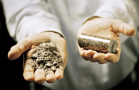
The core is obtained with a drill that has an outer barrel with diamond cutting bits. As the drilling progresses the rock core is undamaged and provides a detailed record of the rock layers. Information on structural features such as joints is preserved. Normally, a field geologist is conducting or supervising the core drilling and will keep detailed records or “logs” of the cores as they are collected and carefully placed into core boxes.
Photos of a drill and associated components are found on Atlas Copco's Conventional Core Drilling page [16]. Take a look at the core bits, core barrels, and drilling rods. You can see a few examples of core boxes and the cores being placed into them.
In contrast to core drilling, chips are obtained with a traditional rotary-percussion drill bit, in which the bits are the same diameter as the hole. The cuttings are collected in a tube inside of the drill rod. This process and the drills are often known as reverse circulation. Cuttings provide information on the type of material and its composition, but structural information is lost. Coring cost per length of the hole is several times more than for cuttings. Both are valuable as we endeavor to define the deposit at a justifiable cost. The difference in the bits that produce the chips versus cores is evident in this picture (Figure 3.1.2).
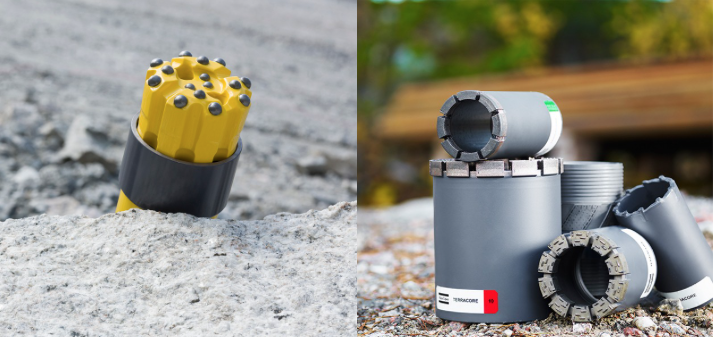
Characteristics of a typical drill rig for surface application are found in this brochure: Atlas Copco Surface Exploration Drill [17]. Later we’ll talk briefly about conducting an exploration program during underground mining. Doing so requires a different configuration of the drill rig, due to the more confined space of the underground mine. Pictures and characteristics of a rig for use in an underground mine are found in this brochure: Atlas Copco UG Exploration Drill [18]
Regardless of which type of drill is used to sample the deposit, it is important to develop a sampling plan, i.e., how many holes will be drilled, and where will these holes be drilled? Will they be spaced uniformly on a grid for example, or perhaps located at irregular intervals? What is the maximum spacing between holes? Practical limitations may limit where we can place our holes. We may not have the surface rights at some points on the pattern, which means we can’t drill from that location. Or other points may be inaccessible due to rugged terrain, the absence of roads to access the area, or maybe there is a shopping mall at the location where we would like to place a hole. Thus, our drilling program may have fewer holes than we’d like due to cost consideration, and the holes may not be placed exactly where we’d prefer to locate them. These are considerations that will keep you awake at night! Why?
Simply put, if we do not take a sufficient number of samples, and we have:
- a large deposit of irregular shape, it is possible that we can completely miss parts of it and grossly underestimate the size of the deposit,
- a small deposit of irregular shape, it is possible that most of our holes will intersect the deposit, leading us to conclude incorrectly that the deposit is massive in size,
- a deposit with a grade or other chemical characteristic that is highly variable, it is possible that we will grossly under or overestimate the value of the deposit.
These are not abstractions! There are real-world examples where these events have transpired, and with very bad consequences for the company. So, how do we know how to locate our drill holes to reduce the likelihood of reaching incorrect conclusions about the deposit? First, knowledge of the geology associated with the target mineral is useful. If we are exploring a coal deposit in western Pennsylvania, we know that it will be a relatively flat lying and tabular deposit. On the other hand, if we’re exploring a gold deposit in Nevada, we can consider that the orebody is likely to consist of veins of varying thickness. Clearly, this geologic knowledge, and the help of a geologist will help us to design an effective sampling program.
There are a few guidelines that have developed over the years.
- A regularly spaced pattern will generally yield more information at a reduced cost.
- The maximum spacing of the holes should be less than the minimum dimension of a deposit that would be mineable with a given mining method.
- Non-vertical holes may be better for steeply dipping veins or lenses. (see Figure 3.6 of the text)
- Data from widely spaced patterns can be evaluated, and then additional holes can be added as appropriate. (see Figure 3.7 of the text)
- Experience gained from other exploration programs is useful. For example,
- A Bureau of Mines study found that holes placed on 1200’ centers would yield sufficient information on the Pittsburgh coal seam
- Patterns for bituminous coal deposits, in general, range from 500’ x 500’ to 3000’ x 3000’
- Typical patterns for porphyry copper deposits are 150’ x 250’ to 200’ x 400’
- Typical patterns for taconite deposits are 100’ x 200’ to 200’ x 300’
It is important that our spacing be such that we can ensure geologic and grade continuity of the ore between holes.
The number of holes and the drilling pattern will help us to accurately estimate the size, shape, and attitude of the orebody, and this is critical. In most cases, we are equally concerned with the grade of the ore or perhaps some other characteristic. Suppose that we’ve done a calculation and we know that the minimum grade at which we can make a profit is 5%, i.e., for each ton of ore, we have 100 lbs. of the mineral of interest; and further, suppose that the grade found in the drill holes ranges from 3% to 7%. Will it be profitable to mine this deposit? Or we may be looking at the CaCO3 content of the limestone, and there will be a minimum concentration that is acceptable for our market. Sometimes it is an impurity in the deposit, which is of greater concern. For example, if the impurities in our salt deposit exceed 2%, we will be unable to sell our product into the more lucrative market for chemical-grade salt, and instead will have to sell it for deicing of roads. In each of these three examples, the value of the deposit will be estimated by analyzing the samples obtained from the drilling program.
Let’s think about this for a case in which the holes are spaced on a regular grid of 1000’, and the diameter of the drill holes is 3”. Suppose we analyze the core for a grade. Think about this: based on a sample of less than 0.1 ft2, we will estimate the grade of the ore over an area of 1,000,000 ft2. This may seem crazy, but if we have prior knowledge about the typical variability of a characteristic in a certain type of deposit, and we have chosen our hole spacing based on that knowledge, then we can be reasonably confident in the estimate.
Fortunately, it is unlikely that you will have to design a sampling program, on your own, in the early years of your career. Nonetheless, you should understand the goals and challenges of the exploration program.
Important outcomes from the exploration program are estimates on the size and value of the deposit. Some of you may have heard terms like "proven" and "probable" or "inferred" to describe the resource or the reserve. These words have a specific meaning and are not to be confused. Not only is this important so that we can understand each other when we talk, but the terms have legal significance so that someone who is considering investing in your mining project is not misled, or worse, deceived. Let’s look at the definitions, and then this will become even more clear.
Resource: a mineral resource is a concentration of naturally occurring solid, liquid, or gaseous material in or on the earth’s crust, in such form and amount that economic extraction of the commodity is potentially feasible.
Resources are further categorized based on the certainty of our estimates.
Measured Mineral Resource: that part of the resource for which tonnage, mineral content, grade, and physical characteristics can be estimated with a high level of confidence. The data must be based on detailed and reliable physical evidence, e.g., drill holes, trenches, outcrops, etc., and sample locations must be spaced sufficiently close to confirm geologic and grade continuity.
Indicated Mineral Resource: similar to a measured mineral resource, but with a reasonable, not a high-level of confidence. Typically, this is because the spacing of the physical samples, e.g., boreholes, is too widely spaced to confirm continuity, but close enough to reasonably assume continuity.
Inferred Mineral Resource: that part of the resource for which tonnage, mineral content, grade, and physical characteristics are known with a low level of confidence because the estimate is inferred from geologic evidence that has not been verified with physical data, e.g., boreholes.
While the mineral resource is an important parameter to determine, investors and mining companies gain little benefit from minerals in the ground. They become valuable if they can be mined. This distinction is accounted for in the definition of a reserve.
Reserve: a mineral reserve is that portion of the mineral resource that can be mined economically at a point in time.
Reserves are further categorized as follows:
Proved Mineral Reserve: that part of a measured mineral resource that can be economically mined at a point in time.
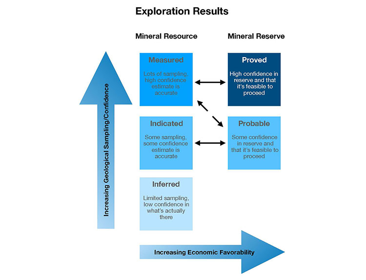
The real value in a potential mining project is in the proved mineral reserve, rather than the probable part of the reserve. The distinction between these two is the degree of certainty in the resource estimate. This further underscores the importance of designing a sampling program and assembling a team of geologists to ensure and confirm geologic and grade continuity.
We have talked about using:
- the drill hole information to define the spatial characteristics of the deposit;
- cores to determine geotechnical features of the orebody and the surrounding rock; and
- cores and cuttings to establish grade and chemical composition, among others, by analyzing the samples in the lab.
I did not mention it earlier, but we will normally conduct metallurgical or process testing on the core or cutting samples too. This information is used to establish certain market qualities of the ore, and to better understand the mineral processing that will be required to beneficiate the ore.
It should also be noted that we can lower instruments down the drill holes, assuming the holes are of sufficient diameter, to “log” the holes. The logging may be done visually using a camera, or with geophysical instruments including gamma-ray and acoustic devices. These logs help to better define the lithology and other characteristics.
A quality exploration program is essential to establish the feasibility of mining the resource, as well as to determine the value of the reserve. While the major exploration work is normally completed to support the feasibility study and subsequently the engineering design of the mine, exploration may continue throughout the life of the mine. In complex ore bodies, exploration drilling will continue in advance of mining throughout the mine’s life. Even in the case of fairly predictable deposits, e.g., a coal seam, conditions may be encountered that require exploratory drilling to define the size of a want area, i.e., an area where the coal has been displaced with a shale or a sandstone, for example. Other than learning a bit more about the methodology for reserve estimation, we are ready to move into the next module where we focus on the development stage.
Lesson 3.2: Reserve Estimation
Lesson 3.2: Reserve Estimation
Reserve estimation can be addressed in two steps.
The first is to calculate the tonnage of the orebody, along with other characteristics of the resource. For a coal deposit, for example, we would calculate the average value for the following parameters: seam thickness, % ash, % sulfur, and BTU (calorific value); and for a metal deposit, we’d calculate the grade. There are other characteristics that would be of interest, depending on the commodity and its market. The calculations are similar regardless of the specific characteristic.
The second is to determine how much of the resource can be mined economically at a point in time. By the way, “at a point in time” usually means using today’s technologies and practices.
Let’s take these in order, starting with the first step.
3.2.1: Step 1 -- Preparing the Data for Estimating the Reserve
3.2.1: Step 1 -- Preparing the Data for Estimating the Reserve
As a starting point, you’re likely to have the following:
- a table of the coordinates of each drill hole,
- the drill log for each hole, and
- analytical results from each hole.
Here are examples of each of these.
The table of coordinates may look like this:
| Corehole | Northing | Easting | Surface Elevation |
|---|---|---|---|
| EM0402 | 200701.67 | 1331172.00 | 1265.26 |
| EM0403 | 201757.90 | 1334065.09 | 1325.60 |
| EM0404 | 199503.09 | 1339026.61 | 1177.98 |
| EM0405 | 199089.71 | 1340085.64 | 1380.07 |
| EM0406 | 198331.70 | 1342255.76 | 1348.82 |
| EM0407 | 198603.62 | 1342968.52 | 1151.73 |
| EM0408 | 197813.63 | 1343153.43 | 1328.48 |
| EM0409 | 200507.09 | 1332119.20 | 1155.50 |
| EM0410 | 199622.88 | 1333356.05 | 1286.98 |
| EM0411 | 197512.23 | 1341681.96 | 1331.86 |
| EM0412 | 198870.72 | 1332353.55 | 1108.05 |
| EM0413 | 198461.45 | 1339504.49 | 1394.94 |
| EM0414 | 197758.15 | 1338897.31 | 1333.38 |
| EM0415 | 198971.83 | 1338532.48 | 1162.52 |
| EM0416 | 198192.38 | 1337999.37 | 1097.55 |
| EM0417 | 198754.13 | 1337377.32 | 1115.72 |
| EM0418 | 199260.00 | 1336708.65 | 1239.12 |
| EM0418A | 198346.95 | 1337042.98 | 1139.57 |
| EM0419 | 198830.00 | 1335962.78 | 1173.48 |
| EM0420 | 199610.69 | 1335682.11 | 1354.33 |
| EM0421 | 199762.29 | 1334786.93 | 1491.54 |
| EM0422 | 199175.87 | 1334493.64 | 1484.68 |
| EM0423 | 200162.85 | 1334193.59 | 1504.45 |
| EM0432 | 197051.92 | 1335828.19 | 1269.23 |
| EM0433 | 197654.10 | 1335366.00 | 1403.45 |
| EM0436 | 197025.92 | 1337879.87 | 1089.72 |
| EM0438 | 196709.76 | 1338854.59 | 1282.14 |
| EM0439 | 196553.37 | 1339724.73 | 1144.93 |
| EM0441 | 198178.28 | 1333567.06 | 1216.20 |
| EM0442 | 195466.82 | 1341429.29 | 1224.64 |
| EMO443 | 195512.30 | 1341984.05 | 1221.25 |
Here is a section for a typical drill log. The complete drill log for this hole can be viewed here: Driller’s Log.pdf [19], and you should look at the full log.
| Formation | Strata Thickness | Depth from Surface |
|---|---|---|
| BLACK SHALE | 0.30 | 878.07 |
| COAL | 0.30 | 878.37 |
| GRAY SHALE | 0.90 | 879.27 |
| COAL | 3.37 | 882.64 |
| DARK GRAY SHALE | 0.02 | 882.66 |
| COAL | 0.10 | 882.76 |
| DARK GRAY SHALE | 0.02 | 882.78 |
| COAL | 3.56 | 886.34 |
| DARK GRAY SHALE | 0.16 | 886.50 |
| LIMESTONE | 0.20 | 886.70 |
| GRAY SHALE | 1.10 | 887.80 |
| LIMESTONE | 2.10 | 889.90 |
| GRAY SHALE | 0.70 | 890.60 |
| LIMESTONE | 0.80 | 891.40 |
| GRAY SHALE | 9.10 | 900.50 |
| BLACK SHALE | 0.30 | 900.80 |
| COAL | 0.40 | 901.20 |
| GRAY CALCAREOUS SHALE | 1.20 | 902.40 |
| GRAY SHALE | 6.00 | 908.40 |
| GRAY SANDY SHALE | 0.70 | 909.10 |
| GRAY SANDSTONE | 0.40 | 909.50 |
| GRAY SHALE | 0.50 | 910.00 |
The analytical results will come from laboratory studies to determine the aforementioned parameters of interest. Here is an example taken from the lab results for the sample obtained from one drill hole.
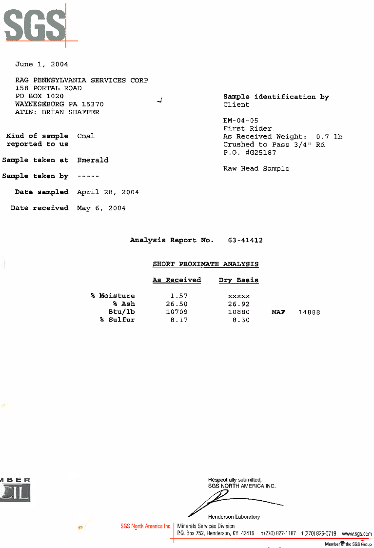
The complete lab report for this hole can be viewed here: Reserve Estimation.pdf [20]
There may be multiple lab reports. The example here focuses on the chemical characteristics of the coal. In many cases, we'll conduct physical tests on the cores to determine geotechnical parameters, e.g. compressive strength, on the ore as well as the rock around the orebody.
We will want to build a database that contains the parameters of interest for each of the holes. If we are interested in determining the average grade, then our table will begin with two columns: drill hole number and the grade for the sample from that hole. Let's suppose that we have a property with 9 holes:
| Hole # | Grade, % |
|---|---|
| 1 | 2 |
| 2 | 3 |
| 3 | 4 |
| 4 | 3 |
| 5 | 4 |
| 6 | 5 |
| 7 | 2 |
| 8 | 3 |
| 9 | 4 |
We want the average grade for the deposit. Is the average grade equal to the arithmetic average, which is 3.33%?
Are the holes spaced uniformly on a grid, like this?
If so, it will be easy to define an area around each hole and then to say that everything within that area has the same properties as those found in the drill hole. Let's draw a box around hole number 5 to illustrate this. Shortly we'll refer to this area as an area of influence.
If the area around each hole were identical, then it would seem reasonable to say that the average grade of this orebody equals the arithmetic average of 3.33%. But wait a minute! We've said nothing about the thickness of the orebody at each hole. Assuming the thickness is identical at each hole, then each hole will represent an identical volume of ore, and computing the arithmetic average yields the correct average grade for the orebody.
However, it's rare that the orebody thickness would be the same at each hole. For the purposes of this example, let's assume a more realistic case in which the thicknesses vary from hole-to-hole. Logically then, a hole through a thicker section of the orebody will represent a greater volume of ore than a hole through a thinner section. If we simply average the two holes together, we will arrive at an incorrect average grade because we have not accounted for the larger contribution of the one hole into the total. We can correct this by using a weighted average, in which the grade of the hole is increased or decreased to reflect the volume that it represents.
3.2.2: The Concept of an Area or Volume of Influence
3.2.2: The Concept of an Area or Volume of Influence
Procedurally, we do this by calculating an area and volume of influence for each hole. The weighted average for the grade, or whatever characteristic is of interest, is obtained by multiplying the value of that characteristic by the volume of influence; and then summing the products and dividing the sum by the sum of the weighted volumes.
Mathematically, this is expressed as:
where = the % grade for the nth hole, and = volume of influence for the nth hole.
Let’s continue with the example by adding the thickness at each hole and inserting columns for the calculated values.The area of influence is the area surrounding each hole, and if the holes are spaced at 400’ intervals, then the area represented by each hole is 1.6x 105ft2.
| Hole # | Area of Influence, ft2 z 103 | Thickness, ft | Volume of Influence, ft3 x 106 | Grade, % | Weighted Grade, %-ft3 x 106 |
|---|---|---|---|---|---|
| 1 | 1600 | 40 | 64 | 2 | 128 |
| 2 | 1600 | 45 | 72 | 3 | 216 |
| 3 | 1600 | 70 | 112 | 4 | 448 |
| 4 | 1600 | 54 | 86.4 | 3 | 259.2 |
| 5 | 1600 | 58 | 92.8 | 4 | 371.2 |
| 6 | 1600 | 70 | 112 | 5 | 560 |
| 7 | 1600 | 42 | 67.2 | 2 | 134.4 |
| 8 | 1600 | 56 | 89.6 | 3 | 268.8 |
| 9 | 1600 | 65 | 104 | 4 | 416 |
| Sum | 14400 | 800 | 2801.6 |
The average grade of the orebody is the weighted grade, 2801 x 106 %-ft3 divided by the volume of influence, 800 x 106 ft3, which equals 3.5%.
Note that the average grade is NOT the arithmetic average of 3.33%. A tenth of a percent error in the grade is quite meaningful. It is important to calculate weighted rather than arithmetic averages in all cases.
In the foregoing example, we had a convenient simplification: the area of influence was the same for each of the holes. In practice, this would rarely be true because the property boundaries are generally irregular and the holes are most likely not spaced evenly. In these common situations, we need a way to determine the influence that a given hole should have in our estimation of the reserve.
Defining an Area or Volume of Influence for a Drill Hole
Consider the following property.

The new challenge here is to determine the area of influence for each hole. Once we have done that, we can continue by using the same procedure that we followed for the previous example.
Each hole is likely to have a different value for the characteristics of interest, and for this discussion let’s say that we are looking at grade. How far from the hole should we assume that the grade of that hole applies? Halfway to an adjacent hole? What if the grade in the adjacent hole is significantly different? Should that alter where we draw the area of influence? Perhaps, we should use a scheme that says the value at the hole decreases inversely as we go further from the hole? In fact, many deterministic and statistical methods have been developed over the years, and some provide better results than others for certain types of ore bodies. Let's take a look at a few methods for determining an area of influence for each drill hole.
3.2.3: Overview of Reserve Estimation Methods
3.2.3: Overview of Reserve Estimation Methods
The polygon method is an old and established approach based on a simple geometric algorithm, in which we construct a polygon around each hole to determine an area of influence for that hole; and then the total volume directly beneath the polygon is assigned the same values as the drill hole from which we constructed the polygon. We’ll take a closer look at his method shortly.
Another method, known as the triangle method, requires that we connect adjacent holes into triangles. The included area of each triangle is assigned the characteristic not of a single hole, but of the weighted average of the three holes forming the triangle. The weighting of the three holes is based on the length of the drill holes.
The inverse distance method is a more complex scheme in which the contribution of a given hole is weighted according to its distance from the block in which the estimate is to be made. The closer a hole is, the more weight is given to its value compared to the values of other holes in the region.
Geostatistical methods employed for ore reserve estimation utilize three-dimensional spatial statistics to improve the quality of the estimate. Classical statistics requires use of a particular distribution model, e.g., the data are normally distributed, and that the samples be independent of one another. Generally, we have insufficient samples of the orebody to assign a distribution, and moreover, the samples are often correlated, i.e., they do not satisfy the independence requirement of classical statistics. Given that the samples, i.e., the drillholes, are limited in number because they are expensive to acquire, often biased, and nearly always smaller in number than is desired, geostatistics is a powerful tool for improving the quality of the estimation.
A prerequisite to a reasonable prediction of the grade of the orebody is a good prediction of the spatial distribution of the grade, or whatever characteristic is of interest. This spatial estimation is accomplished using the sample data and a model known as a variogram, which is used to represent the correlation between the samples. This estimation is often accomplished using a technique known as kriging. Kriging provides an optimal interpolation using the variogram; and the technique is similar to simple interpolation, as we would use in say the inverse distance algorithm, but is different, because it allows us to take into account information that we know about the geology and attendant properties. Based on geologic knowledge of the presence of a certain feature, we will know that the characteristics of all points contained in that feature should be the same or similar. This is an instance where samples are correlated. With geostatistical methods, we can use this knowledge to improve the estimate of grade, or whatever, at points where we have not sampled. The science of geostatistics continues to evolve, becoming more accurate. You will learn the common geostatistical techniques, their strengths, and limitations in MNG 412.
Today, you can enter your exploration data into a computer program and then within minutes, you can have estimates of the resource from several different methods. Then, you will choose which estimate to use. That choice may be based on experience or a heuristic such as selecting the estimate that has the smallest variance. The commercially available mine planning software programs, such as the Carlson software that we use, allow you to employ several different techniques. We are not going to look into these methods in any greater details in this course, with one exception --the polygon method. This method is useful to illustrate the concepts and is a reasonable estimation method in its own right.
The Polygon Method
We begin with a map showing the surface location of the drill holes, and our task is to construct polygons around each hole. The relevant characteristic, say grade, inside of that entire polygon will be the same as the value of that characteristic in the drill hole sample.
We start our work by arbitrarily selecting a drill hole, and then drawing lines between that hole and all the adjacent holes, as shown here.
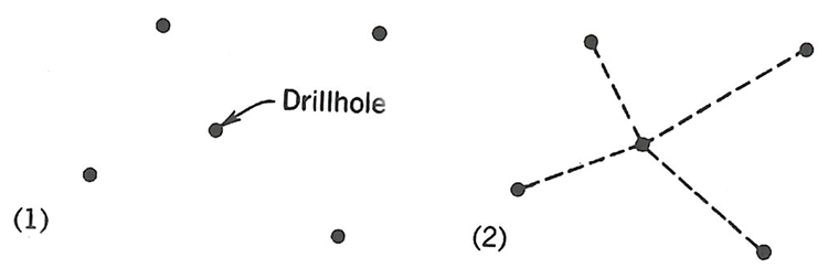
Next, we draw perpendicular bisectors though each of these lines, drawing the bisector line long enough to intersect the other perpendicular bisectors, as shown.
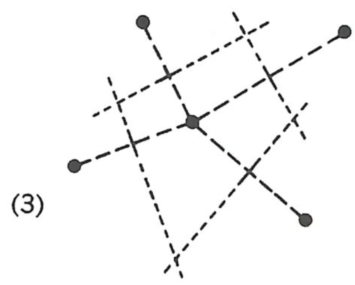
The corners of the polygon are defined by the intersection of the perpendicular bisectors, as shown.
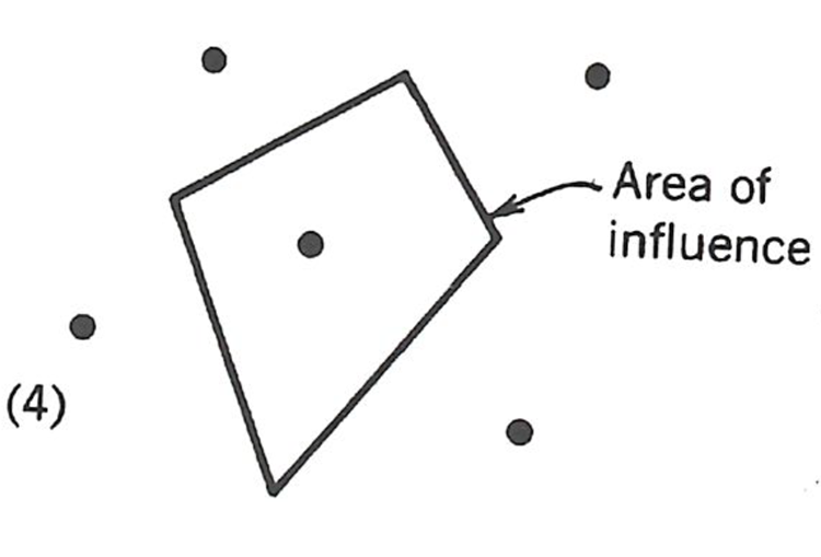
Watch this video (2:59) of a demonstration of using the Polygon Method.
We repeat the process for each hole. Note that if the hole is adjacent to the property boundary, then that boundary line will form a side of the polygon. The result will be a property containing as many polygons as holes, as illustrated here.
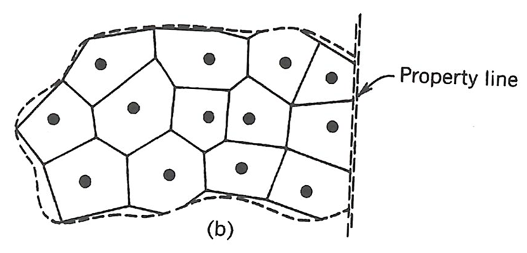
Next, we need to determine the area of each polygon. This can be done manually using a planimeter, or digitally. The result will be an area of influence, i.e., the area of the polygon, for each hole. Then, we can calculate the volume of influence of each polygon, by multiplying the area of influence by the thickness of the ore, or overburden. The next step is to build a table or spreadsheet to facilitate the calculations. We actually did that earlier, in Lesson 3.2.2, and will not repeat it again. At that time, we only calculated the average grade. We could have added any number of other characteristics to the table, and calculated their average value. Examples would include thickness of the deposit and overburden, as well as other characteristics of interest.
3.2.4: Step 2 -- How Much of the Resource is a Reserve?
3.2.4: Step 2 -- How Much of the Resource is a Reserve?
We started this lesson by noting that reserve estimation is completed in two steps. The first is to estimate the size of the resource, which we have now done. The second step is to determine how much of the resource can be mined economically at a point in time.
We’ll need to learn more about mining methods to tackle that question completely, and we will do so in the coming weeks. Notwithstanding, there are two metrics that can be computed very early in this second step. The first metric is known as the cutoff grade, which is basically the lowest grade that can be mined at a profit. The second metric is applicable to shallower deposits that are being evaluated for surface rather than underground mining, and it is known as the stripping ratio. Let’s start with stripping ratios, and let’s use a shallow coal seam for our example.
Stripping Ratios
The coal seam will be underneath layers of soil and rock. The material overlying the seam is known as the overburden. Before we can extract the coal, we first have to remove, i.e., strip, this overburden. It costs money to remove the overburden, and in the simplest terms, the cost of removing the overburden cannot exceed the value of the coal that is exposed.
The stripping ratio is usually taken as the volume of the overburden that must be removed to the weight of the coal that is exposed when this volume of overburden is removed. Thus the units for the stripping ratio will be yd3/ton. Two stripping ratios are used in the prefeasibility or feasibility analyses: overall stripping ratio and the maximum stripping ratio. As mine planning advances beyond the prefeasibility stage, stripping ratios at different cross sections will be calculated as well.
The overall stripping ratio is calculated using the average values for the volume of the overburden and the average value for the weight of the coal (ore). This number is a key indicator for the potential of the project to be profitable. Please remember that these averages are weighted averages.
The maximum stripping ratio, which is also known as the breakeven stripping ratio, is an economic calculation based on the cost of removing the overburden and the value of the coal or ore that is exposed when the overburden is removed. Thus, given the stripping cost and the value of the exposed ore, we can calculate the breakeven or maximum stripping ratio. Stripping costs can be estimated reasonably well, based on the method of overburden removal and the region in which the mining is being conducted. We can find tables of data in handbooks to help us with this estimation. The value of the coal or exposed ore is usually taken to be its selling price. The selling price must account for the mining and processing costs, and the minimum profit that the company requires.
Stripping cost = Value of the exposed coal
where:
- SC = stripping cost, $/yd3
- Vob= volume of overburden that will be removed at breakeven
- Vc= volume of coal that will be exposed by the removal of Vob
- t = thickness of the coal seam
- TF = tonnage factor (density) of the coal, tons/yd3
- SP = selling price of the coal, $/ton
The breakeven or maximum stripping ratio, SRmax, is, therefore:
The value and use of SRmax is illustrated in two examples. Consider the situation represented in the following figure of a coal stripping operation.
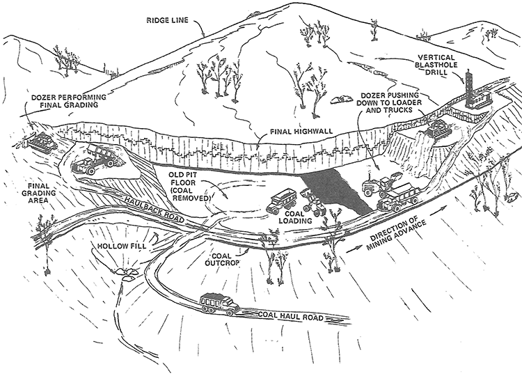
The coal seam is under a hill. Most likely mining started at the edge of the hill where the coal seam outcropped, i.e., intersected the surface. As mining progresses back into the hill, it will be necessary to remove increasing amounts of overburden to expose and mine the coal. At what point does it become uneconomical to remove the overburden to access the coal? Correct –at SRmax! And how do we find SRmax? Correct –using Equation 3.2.3. And therefore, at the point where we are at this maximum stripping ratio, SRmax we will stop mining.
The calculation of stripping ration is slightly more complicated for deposits that are not flat lying, i.e., they are dipping at angle greater than a few degrees; although, conceptually, the process is the same regardless of the spatial characteristics of the deposit. As you'll see, the math is slightly more involved to complete the calculation of the stripping ratio. Let's take a look.
3.2.5: Instantaneous Stripping Ratio
3.2.5: Instantaneous Stripping Ratio
The stripping ratio (SR) refers to the amount of waste material that must be removed for a given amount of ore. The Instantaneous Stripping Ratio (ISR) is the stripping ratio for a given push back, where a tiny slice of material, i.e., ore and/or waste, is removed from a pit wall. This section presents the ISR calculation for a steeply pitching deposit.
Assume an idealized tabular and steeply pitching orebody that outcrops at the surface and dips to the left at ϴ degrees (Figure 3.2.10). Assume that the ore extends down to considerable depth, and that open-pit mining will be used to extract ore. When open-pit mining is no longer economical, an underground mining method will be used to recover the ore. Therefore, we will need to calculate the point at which we will cease surface mining and either go underground or close the mine.
The over-lying waste, i.e., the non-mineral-bearing rock must be removed to uncover and mine the ore. The shape and size of the pit depends upon economic, engineering, and production factors. Assuming all other factors to be constant, as the selling price of the ore increases, the pit size will increase.
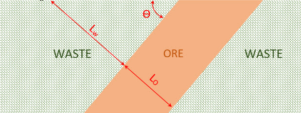
If you were going to calculate the ISR for a “real” orebody for which you had drillhole data, you would utilize one of the computer software packages, such as Carlson. Here the purpose is to teach you the principles, so we are going to make some assumptions to simplify the calculations, and to better illuminate the procedure without getting buried in the math. The assumptions are as follows.
- The seam thickness is constant. The orebody thickness is represented by the length of the ore section (Lo) in the previous diagram. Note that the length of the waste section (Lw) increases as our pit advances deeper. Therefore, as we advance, more of waste will have to be removed to expose a unit of ore, as shown in the next diagram.
- The density of ore and waste are the same.
- All slices have the same strip width (Ws).
- We are looking at a two-diminsional slice of the Earth’s crust. Obviously, the ore and overburden continue into the page and go on for some distance. For our purposes here, we will assume that they go into the page for a distance of 1 unit.
- The slices of the material are mined out perpendicular to the orebody.
Watch this video (3:11) on an explanation of the instantaneous stripping ratio.
Later in this section, I will explain how each of these assumptions affects the calculations. However, it would be instructive for you to pause for a moment and think about each assumption.

Now, let’s calculate the ISR for strip 1:
where T is strip thickness, L is strip length, W is strip width and is material density.
Since the density, width, and thickness of the ore and waste are assumed to be equal, this equation reduces to:
Assume that the ore seam thickness is 40 ft and the length of the waste slice on top of the ore in strips 1, 2 and 3 is 45, 50 and 55, respectively. The ISR for these three strips is calculated as:
This simplified example has illustrated how the length of waste and ore sections will impact the ISR. In a mine, there will be differences in the density of the ore and waste materials. However, the difference can be trivial in some cases. In fact, a real-world example is where there are several waste types in the slice, and the waste materials have densities that are each different from the ore. Therefore, the calculation of ISR using the length ratio does not work. Instead, a generalized IRS calculation must be defined as:
where there are different waste material types in the strip.
If the density differences are not drastic, the simplified form of the calculation will give you a rough estimate of the ISR. If you need more accurate values with higher accuracy level, then you should consider all other parameters in your calculations. Of course, as I mentioned earlier, if you are doing a complex and “real-world” case, you will probably be using a software package; and then, accounting for the myriad of details becomes easier.
By the way, please note that the ISR is independent of the deposit's dip angle.
For this discussion, we have used an orebody of uniform shape and plunging at some angle θ. But what of a deposit with an irregular shape? The same process applies. Therefore, regardless of the shape of the orebody, the above equation can be used to determine ISR for a strip extracted from the side wall of the pit. It should be also noted that different units can be used to express the ISR.
The most popular units for the ISR are tons of waste removed/ton of ore exposed, ft of waste removed/ft of ore exposed, and yd3 of waste removed/ton of ore exposed. The latter is the most common unit in many types of nonmetal operations because there is no value to know the weight of the waste, unless it poses a limit to the trucks. Therefore, the density of waste material does not come into play in the calculations. If there is an issue with a weight limit in the haul trucks, then the tons of waste/ton of ore is an appropriate unit for the ISR or SR.
3.2.6: Maximum Allowable Stripping Ratio (SRmax)
3.2.6: Maximum Allowable Stripping Ratio (SRmax)
Earlier in this lesson, we looked at the maximum stripping ratio, and we did it for coal seam. You will recall that the maximum allowable stripping ratio, SRmax, also called break-even stripping ratio, is the maximum amount of overburden/waste that can be extracted per unit of ore at the economic pit limit. The SRmax is determined solely by economics, to establish the ultimate boundary of the pit, where break even occurs, i.e. the profit margin is zero. As we defined it before,
So, it is a physical quantity that is determined by economics. This value can be simply converted to the unit of tonsw/tono, considering the density of the waste material. If the ISR exceeds the SRmax , then the operation will be uneconomical as the income generated by the ore will be insufficient to offset the costs incurred in mining.
Now, let’s imagine a massive irregular deposit, where copper ore is the only ore that is desired to be mined out. Unlike coal deposits, metals are not extracted in their native form, except in rare cases. Instead, the rock has a small percentage of valuable minerals in it. A copper deposit contains rock that can be profitably mined and processed to extract the copper. However, the amount of copper contained within the rock, i.e. the grade, varies by location. We’ll need to account for this in our calculation of the break-even stripping ratio.
The only difference is that ore grade variation should be taken into account in the calculation. In order to determine the SRmax for such a deposit, the orebody is divided into different blocks of ore. The average ore grade for each block is determined, and then the overall grade of the ore in the slice is calculated as follows:
where is the average ore grade in the slice, is the length of the ore section that has a grade equal to .
After you calculate the average ore grade for the slice, you can use a grade - stripping ratio (g-SR) plot to determine the SRmax associated with the determined average ore grade. Here is an example of a g-SR plot.
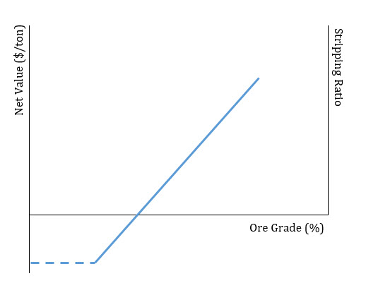
Imagine a copper deposit in which the average copper grade for a strip is 1.05%. Checking the g-SR plot for that deposit, suppose we find out that the SRmax for = 1.05 is equal to 8.5. This means that 8.5 units of waste can be economically removed per unit of ore. If the ISR for the strip is smaller than the SRmax , then the pit could be extended and more strips could be mined profitably. If the ISR and SRmax are equal, then this is a good place for the pit limit. If the ISR is larger than SRmax, then we have passed the economic location for the pit limit.
In MNG 441, you will learn how to determine break-even cutoff grade and draw a g-SR plot using economic parameters. Here, I simply want you to know about this plot and what it is representing.
3.2.7: Impact of Pit Expansion on Stripping Ratio
3.2.7: Impact of Pit Expansion on Stripping Ratio
Imagine a steeply pitching orebody, as shown below. We would like to extract this tabular deposit using open pit mining method. Let’s assume that two pits with different sizes are being considered for this mining operation. We would like to study the impact of pit expansion on stripping ratio by comparing the overall stripping ratios for these two pits.
This figure shows the pit areas as a block model. The smaller pit (Pit A) includes 32 blocks. 16 blocks are ore and the other 16 are waste blocks. Therefore, the stripping ratio is 16/16 = 1. The larger pit includes 437 blocks in total. Using Pit 2, 76 blocks of ore can be extracted. Therefore, the stripping ratio is: (437-76)/76 = 4.75. This example shows that as we expand the pit in a steeply pitching orebody, overall stripping ratio dramatically increases. Therefore, more waste blocks have to be mined out to uncover one block of ore. It should be noted that as we go deeper in an open pit, the unit cost of mining will increase. Because the material will be transported for a longer distance, which takes more time, and which may necessitate that we add additional trucks to the fleet.
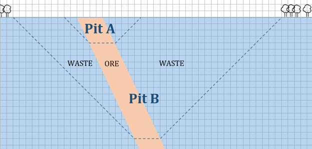
Now, you should be able to:
- Determine ISR for given pit dimensions
- Find the pit limit when the pit dimensions, average ore grade of the strip and g-SR plot are given.
3.2.8: The Concept of a Cutoff Grade
3.2.8: The Concept of a Cutoff Grade
We know that orebody characteristics such as the grade vary spatially within the orebody, and as we approach the boundaries of the deposit, the grade will begin to decrease to zero. Eventually, the cost to mine and process a ton of ore will exceed the value that we can obtain by selling the commodity found in that ton of ore. Mining companies, like other businesses, do not stay in business by selling their product at a loss!
Thus, when we are estimating the amount of the resource that can be mined economically, we’ll have to calculate a cutoff grade; and any ore with a grade lower than the cutoff cannot be counted in the estimate of the reserve. The cutoff grade is the grade at which the cost of mining and processing the ore is equal to the desired selling price of the commodity extracted from the ore.
The cutoff grade is influenced by a few external factors that you can control to a certain extent, and these will be considered in the prefeasibility analysis when the cutoff grade is determined.
Let’s imagine that we have a deposit of copper that we are evaluating. It is a large resource with a grade of 1%. The block below represents 1 ton (T) of in-place ore. We know that the grade is 1%, so we have 20 lb. of copper distributed in that ton of ore. Let’s represent that 20 pounds of copper as a small (not-to-scale) block inside of the larger block.

When we mine this ton of ore, it is likely that we will get some dilution, which occurs when we extract some of the rock surrounding the orebody. In other words we are diluting our ore with this host rock. Why would we do that? We don’t do it on purpose, generally, but, it is a consequence of the mining method and equipment that we select to mine the ore. Imagine that you have a chocolate cake, and this cake has a thin band of raspberry filling in the middle of the cake. Suppose that you are tasked with removing the raspberry layer, and that you do not want to have any of the chocolate layers mixed with the raspberry layer that you are extracting. Further, I will give you a tiny, baby-sized spoon to complete the task on your cake, and I will give your classmate a large serving-size scoop to complete the task on his cake. You both have ten minutes to complete the job, with a goal of minimizing the dilution of the raspberry layer with the chocolate cake..
The outcome of this experiment is evident. The use of the tiny, rather than large spoon will allow the competitor to be more exacting in the removal of the raspberry layer, resulting in far less contamination, i.e. dilution, of the product. In mining terms, we refer to this as the selectivity of the mining method, and some methods are much more selective than others, resulting in far less dilution. Of course, there are tradeoffs between selectivity and other important metrics such as mining cost and productivity. We’ll look closely at this when we study the mining methods. Now, we can continue with our example.
We extract one ton of material, and now we know that this one-ton of material will be diluted with non-ore bearing material, based on how selective our mining method is estimated to be. We can represent this as shown in Figure 3.2.15 by including the waste within the one ton of mined ore. This waste material effectively reduces the copper in the block by the amount of the dilution. Let’s assume an average dilution of 5%. The copper present in the mined block of ore is reduced by 5%, to 19 lb of copper.

Next, our one-ton block of mined material will be routed into the mineral processing plant, where the ore will be separated and concentrated into a saleable product. There will be two output streams from the plant: one containing the saleable product and the other, the tailings, or waste. The physical and chemical methods used to beneficiate the ore are not perfect, and while we can invest more money to improve them, there is a point of diminishing return. Consequently, some saleable product will report to the waste stream, and as such represents a loss. Let’s assume a plant recovery of 90%, meaning that all but 10% of the product in the plant feed will be recovered and report to the product stream. In our example, there is 19 lb. of copper in the feed to the plant and the plant will recover all but 1.9 lb. Thus, the one ton of material that we mined will yield 17.1 lb of copper for sale.

Mathematically, the minimum acceptable grade to mine, i.e. the cutoff grade, occurs when the cost to mine and process the material, (M&P cost), is equal to the value of the product, i.e. its selling price, SP.
We will account for the dilution and recovery losses in the right side of the equation, as these losses are reducing the value of the in-place ore.
where:
- M&P cost = mining & processing cost, $/T
- SP = selling price of the copper, $/lb
- D = dilution
- R = plant recovery
- G = grade
Let’s use some numbers. Assume the following: we have a dilution of 5%, a plant recovery of 92%, a mining and processing cost of $6.80/ton and a selling price of $0.74/lb. Be careful with the units!
Solving the equation for grade, we have:
And substituting our values,
Therefore for this example, the grade of the ore that we choose to mine must have a grade of 0.5% of greater. In other words, the cutoff grade has been determined to be 0.5%, and when you report the size of your reserve, you will include only the tonnage at or greater than 0.5%. Do you understand why you must report it in that way?
Imagine a situation in which your resource contains significant tonnage at slightly less than 0.5%. Likely you will reexamine your dilution and plant recovery assumptions, and explore options for improving both so that you can economically mine the lower grade ore.
We didn’t say much about the selling price itself. Presumable, it is the maximum price that we believe we can reasonably expect to sell our product into the market. The price will need to cover not only our mining and processing costs, but also whatever profit we require. When companies evaluate the merits of opening a new mine they will have certain criteria for establishing the financial merits of the project. They might, for example, require a certain return on their invested capital, a payback within so many years, and so forth. This can all be bundled, at least conceptually, into the required selling price.
Sometimes we will talk about the gross value of the mined ore. The gross value is equal to:
The unit profit is then defined as: Gross Value – Mining & Processing Cost.
To illustrate, assume that we are mining an orebody with a grade of 1.2%, dilution is negligible, and the selling price is $0.74/lb. The gross value is calculated to be $16.34/T and the unit profit is $9.54.
Module 3 Summary
Module 3 Summary
The goal of the exploration stage is to define the resource and estimate the reserve. We’ve learned the basic concepts of resource estimation, and we’ve learned how to estimate a resource using the polygon method. Once we have the resource estimate, we can move on to the reserve estimate.
There are two metrics that can be used to start the determination of how much of the resource is mineable with today’s technologies and practices: cutoff grade and stripping ratio. The former can be used for either surface or underground mining, whereas the latter is applicable only to surface mining. We learned how to calculate both of these metrics in this lesson. In many cases, the reserve will be less than the resource after we subtract off the part of the resource that cannot be economically mined based on the cutoff grade or the stripping ratio.
It may turn out that there are other constraints and problems with mining the resource, and if so, we will have to subtract out those parts that can’t be mined for technical or other reasons. These constraints and problems will become clear as we progress through the remainder of this course, and in the next Module, we’ll identify these “other” factors that will affect the reserve estimate and also consider the merits of the overall project.
Module 4: Development
Module 4 Overview
Module 4 Overview
We have a deposit that we believe is economically viable. Through the exploration program, we’ve defined the size and quality of the deposit. Are we ready to start excavating ore and collecting revenue for our hard work? Not quite! We still have a good amount of work in front of us before we buy our first shovel.
A significant amount of capital must be available to open a mine. In many cases, this money must be raised from investors; whereas, in other cases, the company will have its own capital to invest in the project. In either case, additional engineering studies will be conducted to establish the feasibility of opening a mine. A company with its own capital will have many competing projects for that money, and they will want to allocate it to the project that bests meets their criteria for a return on their capital. Investors, on the other hand, will also want to understand the income potential of their investment. And in either scenario, both will want to understand the risks associated with the project. Consequently, we will have to perform a prefeasibility study to satisfy either potential investors or the company’s board of directors, that we have a deposit with good potential to provide a return on the investment of their money.
In this module, we will focus on the decision criteria for determining whether or not we want to go forward and turn this deposit into a profitable mining operation.
I should mention for completeness, that the development stage also includes the work necessary to access the ore body and prepare for mining. Clearing the land for a surface mine, sinking a shaft for an underground mine, or building the mineral processing plant are examples of development activities. We will talk about all of those things, but we will do so in future modules.
Learning Outcomes
At the successful completion of this module, you should be able to:
- demonstrate a basic understanding of the process to move from a measured resource to a proved reserve, i.e., to establish the extent to which the deposit is economically mineable with today’s technology;
- demonstrate an understanding of the broad categories of factors, i.e. locational, natural & geologic, and socio-economic-political, that will be considered prior to a more detailed feasibility study;
- explain the need for legal standards for reporting on mineral projects; and the three overarching goals of these standards;
- demonstrate knowledge of NI 43-101 and Form 43-101F1, and a familiarity with a “typical” 43-101 report for coal, metal, or industrial mineral projects;
- demonstrate an introductory knowledge of how mining methods are classified, and describe in a few sentences the characteristics of each of the methods:
- surface
- mechanical
- open pit
- open cast
- quarrying
- auger
- aqueous
- hydraulic
- dredging
- solution
- heap leaching
- mechanical
- underground
- unsupported
- room and pillar
- shrinkage stoping
- open stoping
- supported
- cut & fill
- caving
- block caving
- sublevel caving
- longwall
- unsupported
- surface
- demonstrate an understanding of the seven groups of factors affecting the choice of a mining method;
- identify the specific factors that will have the greatest impact on the selection of a mining method, and explain how each has this significant impact on the selection.
Lesson 4.1: So, You Think That You Want to Build a Mine?
Lesson 4.1: So, You Think That You Want to Build a Mine?
The initial stage of development focuses on the merits of the potential mining project. The question of whether or not can we make a decent return on our investment will be of concern to everyone. And the answer is generally complicated by factors that we cannot control, as well as factors that may not be easily known at this early stage of the project.
We'll look at the set of factors that will enter into the decision, but before doing so, I'd mention that already some thought has gone into the merits of the potential project. The investment in prospecting and exploration would not have been made unless there was a belief that a mine could be a good investment. Thus, we see that the continuum of decision making once again blurs the crisp lines that we've established with our five stages in the life of a mine. Regardless of the exact point in time that these factors are considered, they will be addressed early on.
Different authors organize the factors differently, and in more or less detail to suit the purpose of their discussion. Personally, I like the way Hartman and Mutmansky do it in the textbook for this course, and I'll follow, more or less, their categorization here. There are three broad categories of factors to consider: locational, natural and geologic, and socioeconomic. We'll discuss each of these in this lesson.
4.1.1: Locational Factors
4.1.1: Locational Factors
Ore bodies are located where you found them, and often are not ideally located by any definition. They may be inside the Arctic Circle, high up in the Andes Mountains of Peru, or in the tropics of Indonesia to illustrate just a few out-of-the-way places. Occasionally, they are near metropolitan areas or small towns. Regardless, you will assess the following:
Transportation Options
You must get your product to market, and you must be able to get supplies to the mine. Transportation options suited to the one need may be unsuitable for the other, so both must be independently evaluated. Generally, access to rail is necessary. Where is the nearest railway, and will they be willing to serve a spur to your property? Can you get a right-of-way to build a spur? A highway suitable for tractor-trailer use may be needed as well, or in lieu of a railhead on your property. Sometimes, it will be appropriate to move your product on a waterway, e.g., a river or even the ocean. Can you access a load-out facility to get your product on barges or boats, or do you need to build one? These costs will have to be estimated at this stage, as the costs to get supplies to the mine can raise your production costs. Similarly, your customers will bear the cost of transporting the product in most cases. Although you may be able to mine at a competitive cost, your transportation costs could adversely affect your competitiveness. If you are producing a construction aggregate, your practical limit for transporting the product is on the order of 50 miles. If you are producing iron ore, you may be able to transport it for hundreds or even thousands of miles.
Availability of Labor
The labor requirements will depend on the size and type of mine, but in general, you will require experienced miners who are familiar with the method, equipment operators, welders, mechanics, electricians, and skilled managers. Electronics and computer technicians, surveyors, engineers, and accountants are normally part of the human resource requirements, as well. Some of these services may be provided on a regional basis to multiple mines, especially if your new mine will be part of a large company with other mines. If you’re evaluating a potential stone quarry in the Atlanta, Georgia area, labor will be readily available. If the proposed project is an underground gold mine in rural Nevada, you may have to bus the workers for approximately two hours from the nearest town to the mine site –and you will do this each day. If the proposed mine is located in the Australian outback, you will probably set up a fly-in fly-out operation, in which you use jet charters to transport your workers. They will then remain on-site for two or three weeks, working every day, and then return to their home city for a week or so of leave prior to beginning the cycle all over again. You get the idea! Labor availability can span these extremes, and be anywhere in between. Regardless, the effort and the cost to staff the proposed operation will be considered early on.
Infrastructure
The mining operation will require infrastructure, i.e., electricity, water, roads, buildings, housing, hospitals, schools, and so on. Is this already there, or will you have to create it? How long will it take, and what will it cost? Mining engineers of the 19th and early 20th century were, by necessity, quite skilled at building towns and the necessary infrastructure, as well as opening and operating mines. Companies operating internationally in remote or underdeveloped locations still find the need today to develop the infrastructure. The population in the region of these mining operations often experiences a significant improvement in the quality of life, e.g., availability of clean water, excellent medical care, good schools, and so on. Again, however, an early decision includes consideration of the time, effort, and cost to establish such an infrastructure.
Employee Satisfaction
The location and its climate can affect employee satisfaction, which will impact productivity of the workers and your ability to recruit and retain the workforce. These can be significant risks for the proposed project. If the mine is located near an urban area with an abundance of cultural and entertainment opportunities, and the climate is pleasant year round, then your employee satisfaction is likely to be very high. On the other hand, if the mine is inside the Arctic Circle, you may face significant challenges recruiting and retaining a workforce. Of course, you can “buy” some measure of employee satisfaction with high wages and large bonuses.
4.1.2: Natural and Geologic Factors
4.1.2: Natural and Geologic Factors
The technical characteristics of the orebody, the geologic setting in which the orebody is found, and the surface features of the land over the orebody will influence significantly your choice of a mining method and the way that you will lay out the mine and supporting infrastructure. The most important natural and geologic factors that will be assessed include:
Topography
The location of your surface facilities, e.g., shops, warehouses, and roads, will be influenced by the topography. Mountainous terrain creates more challenges than a gently rolling countryside.
Spatial Characteristics of the Orebody
The depth, size, shape, and attitude will have a major impact on the type of mine and mining operation that you can have. A shallow orebody allows consideration of a surface rather than underground mine. A large orebody allows for larger-scale and potentially cheaper bulk methods, and a long life means more time to recover certain costs. The orebody may be tabular in shape, which lends itself to certain types of mining, or it may be a big amorphous blob, or perhaps the ore is contained in sinuous veins. These shapes, in conjunction with other characteristics, will suggest certain mining methods. And finally, there is attitude. The attitude of the orebody is important. After all, who wants to develop a mine in an orebody that has a bad attitude! Just kidding... attitude is a term for the angular orientation of the orebody, and, in particular, we are interested in the vertical angle of the orebody. If the deposit is flat lying, the vertical angle or dip is zero degrees. As we begin to tilt one end of the orebody downward, the dip angle is measured with respect to the horizon. Steeply pitching ore bodies with dip angles of 70 degrees or more are not uncommon. As it turns out, some mining methods require steeply pitching deposits, while others work best with dip angles approaching zero degrees.
Geomechanical Properties of the Orebody and the Surrounding Rock
Undoubtedly, we will want to create openings in the orebody or the surrounding rock as part of the mining process. How difficult will it be, and how much energy will it take to break the ore and the surrounding rock? Will explosives be required? Once we remove a section of ore, will the opening be stable, or will the surrounding ore rush in to fill the void? When the ore is removed will the surrounding rock remain stable, or will it fracture and cave-in? The answers to these questions depend largely on the mechanical properties of the materials. Compressive strength, modulus of elasticity, hardness, and abrasiveness are some of the important properties that will determine how challenging it will be to safely and productively operate the mine. We can take core samples and conduct laboratory tests to quantify the characteristics, and we can avail ourselves of any data that others have compiled on similar deposits.
Geology
Structures such as cleavage patterns, joint sets, and faults can significantly affect the mineability as well as the stability of the materials, regardless of certain mechanical properties such as strength. The stratigraphy, or layers of rock formations, is important in the design of many mine types. The mineralogy of the deposit and the genesis of the orebody will give us an indication of both mining and subsequent mineral processing challenges. The presence of thermal gradients will likely require expensive cooling of the ventilating air. Water-bearing strata or aquifers will increase the complexity of the mining as we work to protect them as well as to deal with groundwater inflows to the mine. There are other examples that will be considered early in the evaluation process, and this once again illustrates the importance of including geologists on the team.
Ore Beneficiation
The ore has physical and chemical properties that will affect the way in which we extract the valuable components from the mined ore. Some copper ores are easier to process than others based on the mineralization, orebody genesis, and so on. These factors will affect the cost of the mineral processing and will be examined before a decision to move forward with the project is made.
4.1.3: Socioeconomic Factors
4.1.3: Socioeconomic Factors
This category is intended to capture a disparate group of factors that are often beyond the control of the mining company, and which can occasionally create large problems for the mining company.
Demographics
The population characteristics are especially relevant to the labor force considerations, which we discussed under locational factors.
Financing and Market Conditions
Generally, mining companies will want to raise capital to finance the proposed mining venture. The prevailing condition of the financial markets will impact the ease or difficulty of raising capital. Similarly, prevailing regional, national, and global economic conditions can radically alter the demand for mined products as well as the price paid for those products. Sometimes, these conditions can change radically from when a project was begun and when it came online. In recent years, the simultaneous crash of both the commodity and energy markets has had disastrous effects for a number of mining companies.
Government Actions
Governments at all levels can incentivize mining by giving tax breaks for example, or they can restrict mining by delaying permit approvals, among other actions. The degree of government regulation is a consideration, and especially the consistency of interpretation and enforcement of regulations, as these can affect the cost of compliance.
Taxes
Tax policies such as income tax and depletion allowances will affect the profitability and, hence, feasibility of a proposed project.
Political Stability
Undertaking projects in lesser-developed countries(LDC) presents a higher risk for investors, and this may make it difficult to obtain financing at a reasonable rate, if at all. Governments change and policies can be overturned or reversed in an instant, and what was a welcoming and investment-friendly government can become quite hostile. Civil wars and terrorism can make it difficult to operate, not to mention the difficulty in recruiting and retaining a skilled workforce. Sometimes, governments will expropriate the company’s assets in the country, e.g., the mine, the equipment, and the reserves – this may occur years after the mine has opened. Despite the risk, companies and investors continue to pursue projects in these areas. Why? The “reward” for investing in higher-risk projects is a much higher rate of return on the investment. Thus, in the prefeasibility stage, the analysis would have to support the likelihood of a much higher rate of return. Otherwise, the project will be a nonstarter. It is difficult to account for these factors, not only because they are largely out of the control of the company, but also because they are difficult to quantify and predict. One can use the historical record as well as seek advice from outside experts, e.g., economists, political analysts in the U.S. State Department, and so on. Practically, we can account for some of these risks by performing risk and sensitivity analyses. For example, if we estimate that the likely selling price is $150/ton, and a worst-case scenario is a selling price of $100/ton, we would evaluate the desirability of the project over this range, and report our findings to those making the decision on the project.
4.1.4: Do You Have an Envelope That I Can Use?
4.1.4: Do You Have an Envelope That I Can Use?
Engineers often talk about doing “back of the envelope” calculations. This is an expression for making a first approximation to a solution or answer. It is a process in which we don’t worry about the details but only the biggest factors that influence the result. By necessity, it requires experience and judgment. The answer is nothing more than a rough estimate and is likely to result in a solution that looks like 1, 10, or 100, i.e., an order-of-magnitude estimate, rather than an exact number like 0.67, 13, or 180! Or, to be more specific here, the team will evaluate the foregoing factors with the goal of concluding one of three outcomes: this project has little chance of success – we need to cut our losses and move on; this project shows strong potential – we need to move into the next stage of the project without delay; or, this project has potential, but without doing further analysis, it is difficult to say that we should move this project to the next stage. Sure, there are shades of gray, but you get the idea of what is happening at this stage.
Reasonably, you may also wonder just who are the people making this decision. That’s a good question. Although the full team may include a number of subject experts, e.g., geologists, mining engineers, among others, the decision-makers are likely to be few in number and are likely to include: a mining engineer with decades of experience in the industry and years of experience in evaluating and bringing new projects online. This person probably has a title with the words “vice-president” in it. There will be a financial wizard. Someone with years of experience in the industry, who can probably do complex discounted cash flow analyses in her head. And there may be a third – perhaps a “rising star” in the organization. Someone with several years of experience, highly motivated, and with the potential to head up this new mining project if it becomes a reality. The model will vary depending on the size of the company and the size of the project, but this will give you an idea of the approach.
So, what’s next? Assuming that the conclusion of our “back-of-the-envelope” analysis is that we still want to build a mine, then we will move to the feasibility-study. This is the subject of Lesson 4.2.
Lesson 4.1 Summary
Lesson 4.1 Summary
The major factors that will affect the desirability and feasibility of a mining project can be divided into three categories. The consideration of the factors will precede any decision to conduct more detailed studies. It is important to understand the three categories, the factors within each category, and in what manner they influence the decision.
Lesson 4.2: Feasibility Studies
Lesson 4.2: Feasibility Studies
A company will fund a prospecting and exploration if, and only if, they believe there is or will be a market for the commodity that they are seeking. As they begin to invest more time and money into the exploration of the deposit, they will concurrently be evaluating the three categories of factors described in the last lesson. If, at some point, they believe that the project is not worth pursuing, they will most likely stop all work on the project and turn their attention to something else. If, at the conclusion of the exploration program and their “back-of-the-envelope” evaluation, they believe that the project has merit, then they will move to conduct a feasibility study. This is the subject of this lesson.
4.2.1: The Nature of Feasibility Studies
4.2.1: The Nature of Feasibility Studies
A company will fund a prospecting and exploration if, and only if, they believe there is or will be a market for the commodity that they are seeking. As they begin to invest more time and money into the exploration of the deposit, they will concurrently be evaluating the three categories of factors described in the last lesson. If at some point, they believe that the project is not worth pursuing, they will most likely stop all work on the project and turn their attention to something else. If at the conclusion of the exploration program, and their “back-of-the-envelope” evaluation, they believe that the project has merit, then they will move to conduct a feasibility study. This is the subject of this lesson.
Practicing engineers and university professors use a variety of adjectives to describe the studies that are conducted and often do so without complete agreement. Common terms include conceptual (±40%), prefeasibility (±25%), feasibility (±10-20%), or definitive (±5% ) studies. The range of terms is meant to convey the cost to perform the study along with the accuracy, (shown parenthetically) of the study. Thus, a conceptual study may cost little to do, but only yield results that are ±40%, whereas the definitive or engineering study in which systems are designed and equipment is selected, will yield highly accurate results. Of course, the latter is laborious and expensive to conduct.
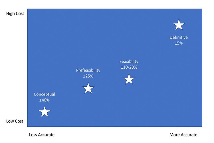
The back-of the-envelope considerations described in Lesson 4.1 would qualify as a conceptual or scoping study. I don’t want you to become overly concerned with the words, and accordingly, I suggest you remember it as follows.
The prefeasibility and feasibility studies have a similar goal, which is to estimate the financial merit of the project. Financial merit is quantified by metrics such as return on investment and the number of years until the operation becomes profitable, among other metrics. These studies will be used to make the go/no-go decision on the project. If the money to finance the project is to be raised publicly on the stock exchanges, then the prefeasibility or feasibility study must be made publicly available. The format for the published study is prescribed by law. So, what is the difference between the two studies? Some engineers or companies simply prefer to use one term instead of the other. Perhaps, the meaningful difference between the two terms is the amount of detail.
A certain amount of detail is prescribed by the legal standards for reporting publicly on projects in which investment is being solicited, and that constitutes the minimum level of detail. Often companies will want to invest more time and money into studying the feasibility of the project. The minimum level may be considered a prefeasibility study, and a more detailed examination of the feasibility may be considered a feasibility study.
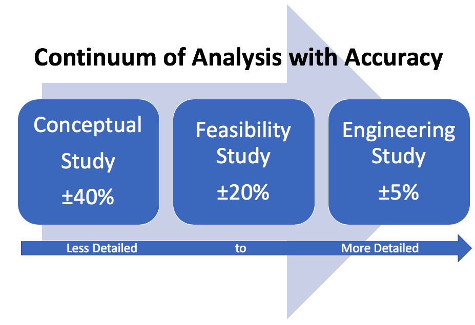
With this understanding behind us, let’s get on with the subject of this lesson – feasibility studies.
The nature of feasibility studies has been prescribed by-laws for projects that will seek investments through public listings, e.g., stock exchanges. Most mining projects obtain at least partial funding through public investment, and as such the way we conduct and report on feasibility in a very similar fashion. Let’s take a look at the requirements, which have only come into being over the past few decades.
Since the earliest days of mineral prospecting and development, there has been no shortage of hucksters and shysters attempting to sell worthless mineral deposits. In the old days, the practice of “salting a claim”, i.e., deliberating adding gold or silver to the sample given to the assay office, separated many a person from their hard-earned money. Over the years, the methods to defraud investors became more sophisticated, the size of the investments became orders of magnitude higher, and when fraud occurred, it was likely to affect not just one or two hapless people, but large numbers. In the late 20th century (1990s), there were a couple of huge scams successfully perpetrated, and these caused great losses around the globe to institutional as well as individual investors. Further, it shook the public’s confidence in mining and made it very difficult for mining companies to raise capital.
The major mining countries, including the United States, Canada, and Australia, developed more rigorous standards for public disclosure of scientific and technical information that will be used to solicit investors. In a nutshell, the standards are attempting to ensure:
- the use of common definitions for words like measured resource;
- full disclosure of the people who developed the public report, including names, experience, and potential conflicts of interest; and
- disclosure of information that has a bearing on the worthiness of the project.
There are no significant differences among the standards used by the different countries, although you must ensure that your report meets the standard of the country in which you are going to list your investment opportunity. For example, if you are going to list on the New York Stock exchange, you must satisfy the U.S. Securities and Exchange Commission’s (SEC) rules, or to list on the Toronto Stock Exchange must comply with the Canadian Securities Administrators (CSA) rules.
We are going to use the Canadian standard because it provides a comprehensive approach that can be easily adapted to the U.S. (SEC), Australian (JORC), or other standards. Even if the intent is not to seek public investment, this standard provides a fine template for reporting on a feasibility study.
4.2.2: The National Instrument 43-101
4.2.2: The National Instrument 43-101
The Canadian Securities Administrators (CSA) developed and released this legal standard, which is referred to as NI 43-101, in 2001. This standard was built on various codes and policies that had been around for many years, as were the standards developed in Australia and the U.S. The standard provides definitions for qualified persons, feasibility studies, and mineral resource categories. We’ve talked about the last two here in class, but not the first. I’ll leave that reading to you. Please visit this link to the CIM Definition Standards for Mineral Resources and Mineral Reserves [23].
As you read through it, take special note of what constitutes a qualified person. Also, note the use of the term modifying factors to describe both the steps to convert a resource to a reserve and the factors that can affect how much of the resource can be converted to a reserve. Finally, you will no doubt be interested in their definition of a pre-feasibility versus a feasibility study. Although it is not part of the standard, the Canadian Institute of Mining (CIM) has prepared and made publicly available a series of best practice documents on the estimation of mineral resources and reserves. Best practice documents are always worth consulting. You may learn something new that you were unaware of, even as a practicing professional. Further, if you deviate from practices that are considered industry-standard practices, you expose yourself to sanctions, lawsuits, and so on. Please visit this Best Practices - Estimation of Mineral Resources and Mineral Reserves [24] document. I suggest that you download it along with the previous document, and save it for future use. At this time, please quickly scan this document to familiarize yourself with the kind of information that it contains so that in the future you will be able to refer to it when you need more detailed guidance.
The “heart and soul” of the standard is known as Form 43-101 F1 [25]. This form essentially specifies the table of contents for the report, and in so doing, is specifying all of the topics that must be addressed in the report. Detailed instructions are given for each of the topical areas. As before, I recommend that you read through this document and save it for future use.
4.2.3: Examples of NI 43-101 Compliant Reports
4.2.3: Examples of NI 43-101 Compliant Reports
Let’s close out this lesson by looking at some examples. These reports have to be made publicly available to investors and their agents, and in many cases, they are available electronically as well as in hard copy. Thus, you can access dozens of these reports freely on the web by doing a search for “NI 43-101”. The quality of these reports will vary. They must meet the minimum requirement of the standard, and some do so – just barely, and are of dubious quality! Some contain a lot more detail than others, i.e., some are definitely preliminary-feasibility studies, whereas others are feasibility studies. There may be times that a company has done more detailed study than it chooses to disclose in the report. That is fine, as long as the additional detail is not considered material. Basically, I am giving you notice that you will see a wide range of detail and quality in these reports that I will give you or that you may find on your own. The list below will give you a nice overview, as it contains different commodities. You’ll want to download and save these reports. You should flip through the pages to become familiar with the type of content; and from time-to-time, you should stop and read a particular section that catches your attention.
National (U.S.) Projects
- Coal: Coal 43-101 elk creek [26]
- Metal: Metal 43-101 gold nugget [27]
- Industrial Minerals: IM Potash 43-101 [28]ochoa [28]
International Projects
- Metal: Metal NI 43-101 Rio Tinto Copper [29]
- Coal: Coal NI 43-101 Pitch Black [30]
4.2.4: What's Next?
4.2.4: What's Next?
Let's imagine that we have completed our feasibility study, and the results indicate that this reserve could be made into a profitable mining operation. Given this, we’ll prepare the formal NI 43-101 report. The next step will be to seek financing for our project. If we are going to seek public investment, we’ll list the opportunity on one or more of the stock exchanges. Concurrently, we may be using the report to gain the interest of private equity groups. Regardless, the next step is to obtain financing.
Sometimes the entity that brought the project to this point has no interest in developing and operating a mine. The entity may be a few individuals backed by a venture capital group or may be a company. Regardless, they are interested in turning their hard work into a pile of cash! A large company may want to purchase their reserve to add it to their reserve base – something that they may not mine for several years. Or, a group that does want to work actively to open a new mine may purchase it. For the purposes of our educational journey, we’ll assume that a mining company conducted, or commissioned, the prospecting and exploration and put together the 43-101 report. As such, the company will want to develop and operate the mine.
The engineers on the team will be engaged in time-critical activities while the search for financing is underway. Time is of the essence! A significant amount of money will have been invested to bring the project to this point – perhaps a hundred thousand dollars for a very small project or millions of dollars for a larger one. What have they earned on this investment so far? Nothing, nada, zip! When will they begin to earn something on the investment? Not until they have a mined product to sell. When will that be? Well, for a stone quarry, it may be in as little as a couple of years. In larger projects, eight-to-ten years is not unusual, and in very large and complex projects, it may be closer to two decades! Think about this – sinking money into a project for years and not seeing a penny back!
I have a proposition for you: how about if each of you loans $1000 to me. In return, I will agree to pay you interest on your money, but I will not begin paying anything to you for 10 years. How many of you are going to jump into this investment opportunity that I am offering? How much interest would you need to be promised in order to seriously consider this investment? Oh, and by the way, if things don’t work out quite the way that I plan, I may not be able to pay you back in full, if at all! Welcome to the world of high risk project financing!
Ok, back to the team of engineers doing time-critical things. What are these things that will be happening while financing is being sought? Consider that the time required to bring the project online will include the time that it takes to:
- acquire access rights, as needed
- prepare permit applications
- wait for permit approval
- conduct the detailed engineering studies
- design and bid surface facilities
- construct surface facilities
- order equipment
- provide access to the orebody
- construct underground facilities (if an underground mine)
- hire the workforce
Permits are required by several state and federal agencies. Not only is it expensive and time-consuming to prepare the application packages, but also some of the permits may require the completion of work that may take a year or two. For example, it may be necessary to sample local streams for one year and include the results in the permit application. Once the permits have been submitted, the review and approval process can be tortuous, as the different agencies review and comment on a particular permit. If there is public resistance to the project, public hearings may be required as part of the permit review process. It is important to plan for and sequence the work that you have to do to achieve a timely filing. For example, you don’t want to add an unnecessary delay because you forgot to hire a consultant to conduct an archeological study that is required in support of one of your permit applications!
While the permitting process is underway, detailed engineering studies will be required to design the various systems, e.g., production, materials handling, power, mineral processing, and so on. These designs will then be used to develop specifications for major plant items, such as the mineral processing, equipment and so on. Bid packages will be prepared for surface facilities such as the mineral processing plant, loading facilities, water treatment, warehouses, shops, and so on. If it is an underground mine, the shaft or other access to the orebody will be bid as well. The construction of these facilities can take a few years. So, exactly when do you need each to be completed, and knowing that, when do you need to initiate the bidding for their construction? These are important questions. Given the cost of capital, you don’t want to make the expenditure prematurely; and at the same time, you are going to look rather foolish if mining is set to commence, but the load-out facilities, which are required to get your product off the property and on the way to your customers, have yet to be constructed!
Some equipment can be received within weeks of order, whereas others will be fabricated on-demand, and lead times of several months are common. Choosing the correct point in time to place orders is important.
Accessing the deposit for a surface mine takes less time than for an underground mine, although it can take several weeks to months and must be planned. Underground access can be far more complex. It may take a year to sink a shaft and to develop the spaces around the shaft bottom. And then, depending on the deposit and mining method, it can take weeks to a year or more to develop the workings necessary for mining.
I started this discussion with the question of what are the activities that will be undertaken concurrently with the effort to obtain financing. Clearly, many of the activities that I’ve just outlined will not be initiated until financing is in-hand. However, these activities will be in various stages of planning before financing is completed. Early on, it is crucial that an accurate and detailed project plan be prepared. All of the tasks that need to be performed will be represented on a network diagram known as a PERT diagram. Detailed timing charts, known as Gantt Charts, will be prepared to document the time relationships of the activities that must be completed when they need to be completed and started, and their duration. These diagrams will be used to determine the critical path and when mining can begin, to assess the effect of delays, and ultimately to monitor the progress of the project. Resource requirements will be documented and integrated into the project plan as well. The size and complexity of these projects necessitate the use of project management software, such as MS Project.
By the time financing has been secured, a good project plan will have been completed. Further, work will be well underway to prepare the permit applications; and it is likely that detailed engineering design and analysis will be underway.
The engineering design and analysis of the many systems will be the subject of courses such as MNG 404 Materials handling; MNG 411 Systems Analysis; MNG 422 Ventilation, MNG 431 Rock Mechanics; MNG 410 Underground Mining; and MNG 441 Surface Mining. You will learn more about project management techniques in the capstone design course, MNG 451, where you will conduct a 43-101 feasibility study.
Lesson 4.2 Summary
Lesson 4.2 Summary
The next logical step in our progression through this course is to talk about the unit and auxiliary operations. Most mining operations use the same small set of operations to execute the entire mining cycle, and as such, it is convenient to examine them prior to studying each mining method. We will do this in the next Module. Speaking of mining methods, there is one bit of unfinished business before we move on to the next module.
The selection of a mining method is part of the feasibility study. The choice of the method will affect how much of the resource can be recovered, and that, of course, affects the reserve that you can report. When you reviewed Form 43-101F, you saw a section devoted to the mining method, and this is the reason why. Keep in mind that we are not designing the mine at this stage, merely choosing a method based on the data and information we have available to us. In the next lesson, we will look at the set of mining methods and the factors that will influence our selection of a method.
Lesson 4.3: Mining Methods
Lesson 4.3: Mining Methods
We are going to identify the various mining methods in this lesson, and then we are going to look at the factors that affect our selection of a method. Later in the course, we will study the methods in more detail, but at this stage, we want to understand why a particular method would be identified in the feasibility study.
Classification of Mining Methods
We will use a traditional taxonomy to classify the mining methods. At the top level, mining methods are either surface or underground. The difference rests solely with where we access the orebody: are we accessing it from the surface or is it too deep beneath the surface, such that we can only economically access it from underground?
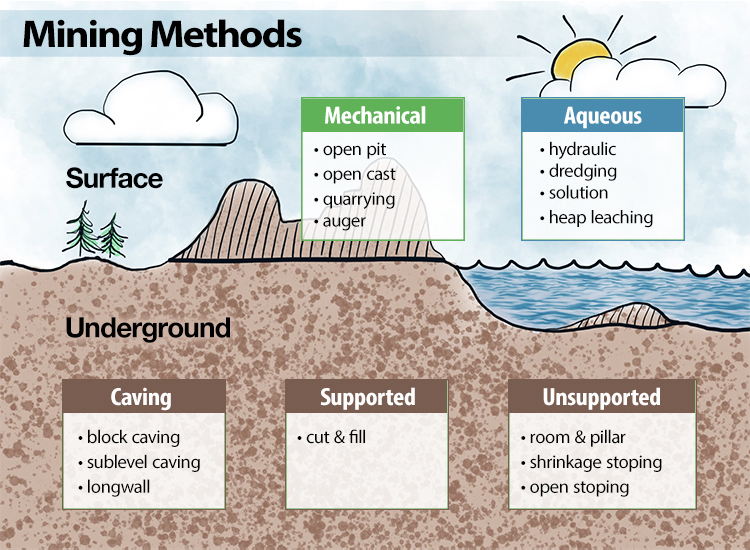
4.3.1: Surface Mining Methods
4.3.1: Surface Mining Methods
Surface mining methods are traditionally divided into two classes: mechanical and aqueous. Mechanical methods rely on breaking the ore by mechanical means, and aqueous methods rely on the use of water or another solvent, e.g. an acid, to break down the ore and facilitate its removal.
Mechanical Methods
Open pit mining
This type of mining is used for near-surface deposits, primarily metal and nonmetal. The overburden is hauled away to a waste area and a large pit is excavated into the orebody. The depth of the pit is increased by removing material in successive benches. A few examples of commodities mined by this method would include iron and diamonds.
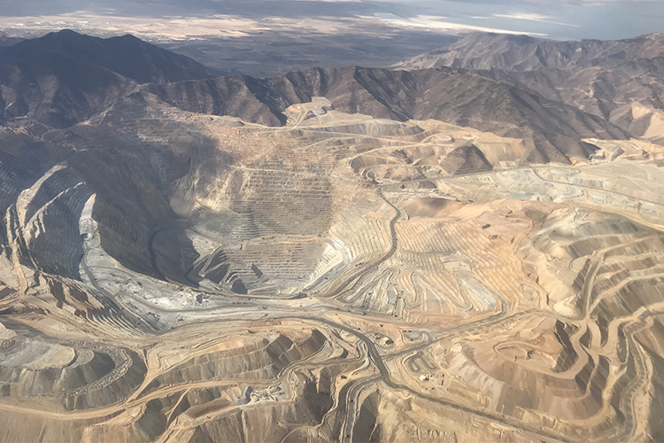
Open cast mining
Open cast mining is also known as strip mining and is used for bedded deposits, and most commonly for coal. Although it is similar to open pit mining, the distinguishing characteristic is that the overburden is not hauled away to waste dumps; but rather, it is immediately cast directly into the adjacent mined-out cut. There are two important sub methods for open cast mining. One is known as area mining, and is applicable when the terrain is relatively flat; and the other is contour mining, better suited for mountains regions. A few examples of commodities mined by this method include coal and phosphate.
Quarrying
Quarrying is a method of extracting dimension stone. The term dimension stone encompasses certain stone products used for architectural purposes such as granite countertops, marble flooring, and monuments, among a few others. The goal in the mining of these products is to remove large slabs that can be cut and machined to exacting architectural applications. Unlike open pit mining in which benching is required to prevent failure of the sides or pit slopes, the high strength and competency of the rock mass in quarries is such that vertical walls of 1000’ or more can be excavated. Now that I’ve given you the classical mining engineering definition of quarrying, you should be aware that just about everybody uses this word, "quarry" to describe any open pit operation in stone! Oh well… A few examples of commodities mined by this method include Georgia marble and Vermont granite.
Auger mining
This is a method to recover additional coal from under the highwall of a contour mine, when the ultimate stripping ratio has been achieved in open cast operations. It is sometimes referred to as secondary mining because it is done after the open cast mine has reached an economic limit.
Aqueous Methods
Hydraulic mining
Hydraulic mining is used for a limited class of deposits that are characterized as loosely consolidated, such as placer-type deposits. A high-pressure water canon is used to dislodge the deposit, and the resulting solution is either pumped to a processing plant or a gravity separation is performed at the mine site using something like a sluice. A few examples of commodities mined by this method include gold and kaolin.
Dredging
This method is used for underwater recovery of loosely consolidated materials using a floating mining machine known as a dredge. In some cases, the deposits are naturally underwater, while in others the area is flooded, creating an artificial lake on which the dredge operates. A few examples of commodities mined by this method include sand and gravel.
Solution mining
Solution mining is used to recover deep deposits that would be uneconomical using underground methods, but only if the ore can be easily dissolved by a solvent. In this method, holes are drilled from the surface into the deposit. A solvent is pumped down one hole, and the resulting solution with the dissolved mineral is pumped out another hole. This solute or pregnant liquor, as it is often known, is processed to extract the mineral of interest. In some cases only one hole is used, but the hole has an inner and outer section to separate the in-going solvent from the out-coming solute. Water, acid, and steam are common solvents. A few examples of commodities mined by this method include uranium and sulfur.
Heap leaching
Heap leaching was used many years ago as a method to recover very low percentages of metal remaining in the tailings from mineral processing plants. Large piles, i.e., heaps, of the tailings of low-grade ore were created, a solvent was allowed to drip and percolate down through the heap, and then the pregnant liquor was recovered and processed. In this fashion, it is a secondary method. In recent years it has been used with increasing frequency to recover high-value metals such as gold from very low-grade ores. A few examples of commodities mined by this method include copper and gold.
4.3.2: Underground Mining Methods
4.3.2: Underground Mining Methods
Underground mining methods become necessary when the stripping ratio becomes uneconomical, or occasionally when the surface use of the land would prohibit surface mining. Underground methods are traditionally broken into three classes: unsupported, supported, and caving methods. These classes reflect the competency of the orebody and host rock more than anything else. If you excavate an underground opening in the ore or the rock, is the opening stable -- i.e., will it remain open for an extended period, or will it begin to fall in? If it is unstable, i.e., the surrounding ore or rock breaks up and falls into the opening, how much support would be required to keep the opening from caving in? The answers to these questions lead us to choose mining methods from one of the three classes. Unsupported methods require the addition of minimal artificial supports to secure a stable opening, whereas the supported methods require the addition of major support to keep the openings from caving in. Finally the third class is, at first glance, counterintuitive: in general our goal is to create stable openings underground for obvious reasons, but the methods in this class will only work if the host rock or orebody will cave easily under its own weight -- the caving methods actually depend on this caving action to function safely and productively!
Unsupported Methods
Room and Pillar mining
This method of mining is used to recover bedded deposits that are horizontal or nearly horizontal when the orebody and the surrounding rock are reasonably competent. Parallel openings are mined in the ore, i.e., rooms, and blocks of ore, i.e., pillars, are left in place to support the overlying strata. Other than the pillars, little artificial support is required and often consists of bolts placed into the overlying strata to pin the layers together, making them behave like a strong laminated beam. A few examples of commodities mined by this method would include coal, lead, limestone, and salt. Historically, if the pillars were irregular in size and placement, which is more likely to occur in certain metal and nonmetal deposits, this method was known as stope and pillar, rather than room and pillar. You will still hear the word stope and pillar being used, but the distinction is now largely irrelevant. This method accounts for the vast majority of all underground mining in the U.S, and likely the world. Watch this video (2:58) created by Caterpillar showing the use of their equipment in room and pillar mining.
Shrinkage stoping
Shrinkage stoping is used to recover steeply dipping orebodies when the ore and host rock are reasonably competent. A stope, i.e., a large section of the mine where active production is occurring, is mined, but the broken ore is not removed, but rather is left in place to support the walls of the stope until the time when all of the broken ore will be removed. Since rock swells, i.e., increases in volume when it is broken, it is necessary to draw off some of the broken ore as the stope is progressively mined. The name of this method derives from this drawing off or shrinkage of the stope. A modern and important variant of this method is known as vertical crater retreat (VCR) mining. A few examples of commodities mined by this method include iron and palladium. Watch this video (3:01) created by Atlas Copco demonstrating sublevel stoping mining method.
Open stoping
This type of mining is used to recover steeply dipping orebodies in competent rock. The ore is removed from the stope as soon as it is mined. Sublevel stoping and big-hole stoping are the important variants in use today. A few examples of commodities mined by this method include iron and lead/zinc.
Supported Methods
Supported methods historically included cut and fill stoping, stull stoping, and square set stoping. However, the last two are no longer used due to their extreme cost. We’ll confine our discussion to cut and fill stoping.
Cut and fill
Cut and fill is used to recover ore from weaker strength materials, in which the openings will not remain stable after the ore is removed, and the overlying strata cannot be allowed to cave. A slice of the orebody is mined and immediately after the ore is removed, backfill is placed into the opening to support the ore above. The next slice is removed, the cut is then backfilled, and the process repeats. As you might imagine, this is a very expensive method to use, and consequently, it would be used only for the recovery of high value ores. An example of a commodity mined by this method is gold. Watch this video (2:58) created by Altas Copco on Cut and Fill mining method.
Caving methods
Caving methods include block caving, sublevel caving, and longwall mining. For emphasis, allow me to repeat what I said earlier: caving methods are used in settings where the ore or the host rock is so weak that it cannot support its own weight for any period of time; the methods only work if the rock or the ore will readily cave under its own weight.
Block caving
This method is used in weak and massive orebodies, in which the ore is undercut, and then as the broken ore is removed the remainder of the orebody collapses into this void, and as more ore is withdrawn, the caving continues. Typically the host rock is fairly strong, although ultimately it tends to cave into the void created from removing the ore. The fracturing and caving often break through to the surface. Watch this video (3:16) created by Atlas Copco on Block Caving Mining Method
Sublevel caving
This type of caving is used in strong and massive orebodies in which the host rock is very weak and quickly caves into the void created by removing the core. As in block caving, the cave will ultimately reach the surface. Watch this video (3:05) created by Atlas Copco on sublevel caving mining methods.
Longwall mining
Longwall mining is a type of caving, applied to a horizontal tabular deposit such as coal. While block and sublevel caving are essentially vertically advancing metal mining methods, longwall mining is applied to relatively thin and flat-lying deposits – most often coal, but occasionally an industrial mineral such as trona. The coal seam is extracted completely between the access roads, and then as mining retreats, the overlying strata caves into the void left by removing the coal. Watch this video (5:31) created by Clearcut Mining Solutions showing logwall mining method.
Our goal in attempting to classify mining methods is to make it easier to learn the methods, because methods in a given class tend to work best in similar circumstances. Similarly, there tend to be just a few factors that differentiate the methods. By examining the classification scheme, we make it easier to remember the methods and the characteristics under which they can or cannot be used. It’s also useful to note that there is nothing sacred about the choice of a method. If five years down the road the characteristics of the deposit are changing, then another method will be employed. There are examples of mines utilizing three different mining methods over a 15-year period, as they adapt the mining method to the evolving geological conditions. Sometimes, one method is employed as the primary mining method, but another is used on retreat to recover pillars, for example. We’ll look at some of those cases later as well.
4.3.3: Why Do We Choose One Method over Another?
4.3.3: Why Do We Choose One Method over Another?
There are many factors that can affect the choice of a mining method. However, a relatively small number of them will dictate the choice. The others may affect the layout of that method, or other details, but rarely do they eliminate a method from consideration or drive the selection of a method. Let’s take a look at a comprehensive set of factors and understand what they mean. Then, we’ll step back, take a deep breath, and see how uncomplicated it can really be! Here is a comprehensive list with a few annotations to indicate the significance of the factor.
Spatial characteristics of the deposit
These factors play a dominant role in the choice of a mining method because they largely decide the choice between surface and underground mining, affect the production rate, and determine the method of materials handling and the layout of the mine in the ore body.
- size (especially height, thickness, and overall dimensions)
- shape (tabular, lenticular, massive, or irregular)
- attitude (inclination or dip)
- depth (mean and extreme values, stripping ratio)
- regularity of the ore boundaries
- existence of previous mining
Geologic and hydrologic conditions
Geologic characteristics of the ore and surrounding country rock influence method selection, especially choices between selective and nonselective methods, and ground support requirements for underground mines. Hydrology affects drainage and pumping requirements, both surface and underground. Mineralogy governs solution mining, mineral processing, and smelting requirements.
- mineralogy and petrography (e.g., sulfides vs. oxides in copper)
- chemical composition (primary and secondary minerals)
- deposit structure (folds, faults, discontinuities, intrusions)
- planes of weakness (joints, fractures, shear zones, cleavage in minerals, cleat in coal)
- uniformity of grade
- alteration and weathered zones
- existence of strata gases
Geotechnical (soil and rock mechanics) properties
The mechanical properties of ore and waste are key factors in selecting the equipment in a surface mine and selecting the class of methods (unsupported, supported, and caving) if underground.
- elastic properties (strength, modulus of elasticity, Poisson's ratio, etc.)
- plastic or viscoelastic behavior (flow, creep)
- state of stress (pre-mining, post-mining)
- rock mass rating (overall ability of openings to stand unsupported or with support)
- other physical properties affecting competence (specific gravity, voids, porosity, permeability, moisture content, etc.)
Economic considerations
Ultimately, economics determines whether a mining method should be chosen, because economic factors affect output, investment, cash flow, payback period, and profit.
- reserves (tonnage and grade)
- production rate (output per unit time)
- mine life (total operating period for development and exploitation)
- productivity (tons /employee hour)
- comparative mining costs of suitable methods
- comparative capital costs of suitable methods
Technological factors
The best match between the natural conditions and the mining method is sought. Specific methods may be excluded because of their adverse effects on subsequent operations (e.g., processing, smelting, environmental problems, etc.).
- recovery (proportion of the ore that is extracted)
- dilution (amount of waste that must be produced with the ore)
- flexibility of the method to changing conditions
- selectivity of the method (ability to extract ore and leave waste)
- concentration or dispersion of workings
- ability to mechanize and automate
- capital and labor intensities
Safety, Health, Environmental concerns
The physical, social, political, and economic climate must be considered and will, on occasion, require that a mining method be rejected because of these concerns. The impact of one mining method over another method on the environment must be considered. Similarly the ability to provide the highest level of safety and health with one method as compared to a competing method must be considered.
- ground control to maintain integrity of openings
- subsidence, or caving effects at the surface; or affect on ground water system
- atmospheric control (ventilation, air quality control, heat and humidity control)
- availability of suitable waste disposal areas
- workforce (availability, training, living, community conditions)
- comparative safety conditions of the suitable mining methods
4.3.4: Putting it into Perspective
4.3.4: Putting it into Perspective
So there you have it – the 37 factors that will influence your choice of a mining method… but how and when? Fortunately, this all reduces to a few major drivers.
First is depth...
If I know the depth of the deposit and the thickness of the overburden, I can do a few calculations and decide whether it is most likely going to be a surface or an underground mine. With this one factor, I’ve excluded or included half of the mining methods. Here, our decision tree has to split based on surface or underground. Let’s go down the surface path first.
If it’s a near-surface deposit, then tell me if is metal, nonmetal, or coal deposit. If it’s a noncoal deposit, then open pit is likely. If it’s coal, then open cast is likely.
If it’s coal, then tell me about the topography. If it is flat lying, area mining is likely. If it is mountainous, then contour mining is the better choice.
On the other hand, if it is a low-grade and deep deposit, then solution mining will be considered if the mineral is one that is known to be recoverable with solution mining methods.
If the deposit is dimension stone, then I know it is going to be a quarry operation.
Ok, so what if an underground method is indicated?
The process is not quite as simple as for narrowing the field of surface methods, but almost so. Let’s go down that path and see.
First, I’d like to know about the attitude. Is the deposit horizontal or nearly so? If so, I’ve excluded several of the underground methods, e.g., shrinkage stoping and open stoping. On the other hand, if it is steeply pitching, I can eliminate room and pillar.
Next, I’d like to know about the competency of the host rock and the deposit. That will further narrow the field of potential methods.
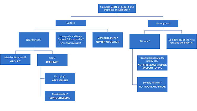
This will all become clearer...
After we’ve studied the methods in more detail, this will become clearer. At this time, I am simply trying to make the process of selecting a method seem less intimidating. Sure, all of the 37 factors that I listed earlier are relevant, and that will become apparent by the end of the course. The ones with the greatest effect, in general, are:
- depth;
- surface features (especially for, but not limited to surface methods);
- attitude, shape, and size (extent);
- geotechnical characteristics of the orebody and the host rock;
- grade and uniformity;
- production requirements.
If these are the factors that essentially drive the selection process, then why do we bother listing the others? You will be in a stronger position to answer this at the end of the semester, but let me make a few remarks now, to give you a better feel for the relevance of the other factors, and why you should learn them!
- Safety considerations, as well as productivity, are responsible for the preference of vertical crater retreat mining rather than shrinkage stoping.
- Selectivity will be important for high grade ores in which the precious metal is concentrated in narrow veins or bands.
- Presence of discontinuities could nix the use of one caving method but be largely irrelevant for a different caving method.
Lesson 4.3 Summary
Lesson 4.3 Summary
In this lesson, we’ve introduced the different mining methods used to exploit mineral deposits. We’ve characterized them into broad categories of underground and surface. Within each category, we established classes of methods, and then we identified the individual mining methods belonging to each class. We saw that a class represented a few specific characteristics of the deposit, and as such the methods in that class are well suited for deposits with those characteristics.
The choice of a specific mining method may require consideration of several factors, and we looked at six groups of factors totaling 37 in all. Although any of these factors can affect the selection of a mining method, a small set of the 37 have a disproportionate effect on the choice, and we identified those.
You will develop a better understanding of the details of the mining methods and the many factors that affect the choice of the method as we work through this course. Despite the lack of detail at this stage, you will find the material covered in this lesson to be quite useful as we continue into the remaining modules.
Regardless of which method we use, it is likely that the similar unit and auxiliary operations will be used during exploitation. The equipment itself may be very different, but the operations are similar from an engineering perspective. We’ll take a look at this in the next module.
Module 5: Unit and Auxiliary Operations
Module 5 Overview
Module 5 Overview
If we were to step back and take a high-level view of mining operations, we would notice many differences based on the mining method and the peculiarities of a specific deposit. We would also see certain commonalities among many of the methods. The details would vary, and the names of the equipment might change, but yet we would see similar operations being repeated over and over again.
The operations directly related to extracting and removing the ore are known as the unit operations, and the operations that serve to support the mining activity are known as auxiliary operations. In this module, we will study these operations, and in so doing, we will be able to apply them to virtually any mining method.
Learning Outcomes
At the successful completion of this module, you should be able to:
- describe the two fundamental operations of exploitation, and the unit operations for these in soft and hard rock;
- recognize the equipment used for ore winning and materials handling, and describe the characteristics of that piece of equipment;
- list and describe common auxiliary operations;
- explain what is meant by ground control, the difference between active and passive supports, and common practices for support the ground;
- describe a roof bolt and how it works;
- identify typical power sources for mining equipment, and explain the advantages of each;
- explain the need for ventilation in underground mines;
- explain why maintenance is such an important auxiliary operation;
- define availability and calculate the availability of a production unit;
- define production and productivity;
- demonstrate a knowledge of the difference between cyclic and continuous operations;
- “value of a minute” in production settings,
- types of delays,
- continuous mining machines,
- examples of batch and continuous materials handling equipment used in surface and underground methods,
- trends in materials handling equipment;
- explain the difference between continuous mining machines in soft rock versus hard rock, and the limitation on the use of these machines in hardrock mines.
Lesson 5.1: Introduction to the Cycle of Operations
Lesson 5.1: Introduction to the Cycle of Operations
The process of exploitation reduces to two fundamental operations: winning, i.e., freeing the ore from the orebody, although that term is rarely used in ordinary conversation; and materials handling, i.e., transporting the ore to the mineral processing plant. Winning and handling are repeated over and over again, i.e., they are cyclic.
The fundamental processes of freeing the ore fall into two categories. In softer deposits, we can use equipment to excavate or essentially “dig” the ore. In harder material, we will have to use explosives to blast the ore free from the orebody, and to blast the ore, we must first drill holes to place the explosive that will be used. Once the ore has been freed, it must be loaded so that it can be hauled.
Thus, the two fundamental operations defining the exploitation of ore, winning and materials handling, consist of the following unit operations:
Harder Materials: drill, blast, load, and haul
Softer Materials: excavate, load, and haul
These unit operations also define what is known as the basic production cycle.
Obviously softer and harder are relative terms and are deliberately vague. The compressive strength is an important parameter to separate ores into the “softer-harder” categories, but other parameters can affect whether or not it is practical to excavate rather than drill and blast. Moreover, as cutting technology improves, it is becoming practical to excavate materials today that we wouldn’t have considered twenty years ago. Examples of softer ores that can be excavated include coal, salt, and trona. Examples of harder ores that require drilling and blasting include limestone, copper, and lead. Some ores, for example, salt and potash, are exploited both ways. We will discuss the reasons for that in this lesson.
Every mining method, with the exception of solution mining, employs these unit operations. (We could force fit solution mining into this paradigm, but it would be a bit weird, so we’ll not do so. Besides, solution mining accounts for a very small amount of all mining.) The specific equipment chosen to implement each of the unit operations may vary by mining method, and even within methods there may be equipment and practices variation. In this Module, we’ll focus on the overarching principles, and we’ll take a look at the equipment that is commonly used.
There is one other category of common operations known as auxiliary operations. Auxiliary operations support the production cycle and are essential to it, and like the unit operations, they are repeated over and over again; and as with the unit operations, the specifics of the auxiliary operations will vary by mining method and the characteristics of the orebody. We’ll say a few things about the auxiliary operations in this Module, but save most of our discussion on these for when we look at the mining methods. The list of auxiliary operations can become quite long if you attempt to include every single activity that must occur during mining. We’re not going to try to do that, but a few are of special note.
Ground control and power are two auxiliary operations that are essential to every mining method. In underground mines, these two would be augmented with ventilation as an essential and major auxiliary operation. In surface mines, an argument could be made that reclamation would be an essential and major auxiliary operation. Others would argue that maintenance should be on the list of essential and major auxiliary operations. There are other auxiliary operations that are more specific to the method, such as preparing and placing backfill in mines employing the cut and fill method; or commodity, such as the explosion prevention activities in mines, regardless of method, that have explosive gas.
Taken together, the unit operations and auxiliary operations constitute the cycle of operations, which will be different among the different mining methods. Accordingly, we will discuss and document the cycle of operations that are inherent to each when we look at the individual methods in more detail.
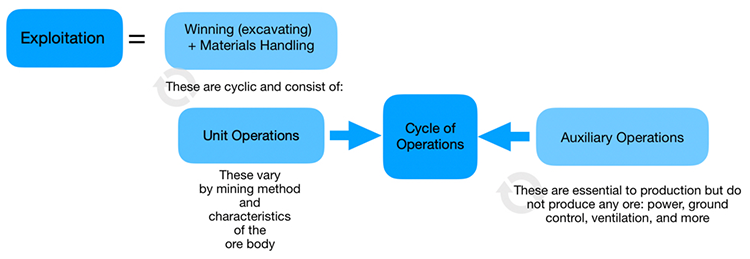
In this Module, we’ll examine engineering concepts that apply to unit operations, which will then facilitate a more detailed analysis when we look at the specific mining methods, and we’ll identify the names and general characteristics of the equipment used for these operations. In the remainder of this lesson, I want to introduce you to the equipment used in the production cycle.
5.1.1: Equipment for Winning the Ore
5.1.1: Equipment for Winning the Ore
Commonly used equipment for winning the ore includes the items listed below. The selection of a specific size or type of equipment generally requires an engineering analysis. Here, the goal is simply to familiarize you with the name and function of the major pieces of equipment.
5.1.1a: Drills, Explosives Loaders, and Rippers
5.1.1a: Drills, Explosives Loaders, and Rippers
Drills
Drills are used to create a hole of a certain diameter and depth. Occasionally, the goal of drilling is to create an empty hole, but more often, the purpose of the hole is to accept explosives. The major components of a drill include the bit, which fragments the rock; a power source that transfers energy to the bit; and lengths of drill steel, sometimes called the drill string, that connect the bit to the drill rig proper. Drills vary by: the method of rock penetration, e.g., rotary or percussion; the location of the power source, which can be at the top of the drill string, e.g., top hammer, or at the bit, e.g., down-the-hole; primary method of powering the drill, e.g., diesel engine, electric motor, or compressed-air; and the method of mounting the drill rig, e.g., track-mounted or tire mounted.
Here, we have a track-mounted down-the-hole drill with an articulating boom to facilitate drilling holes at precise angles.
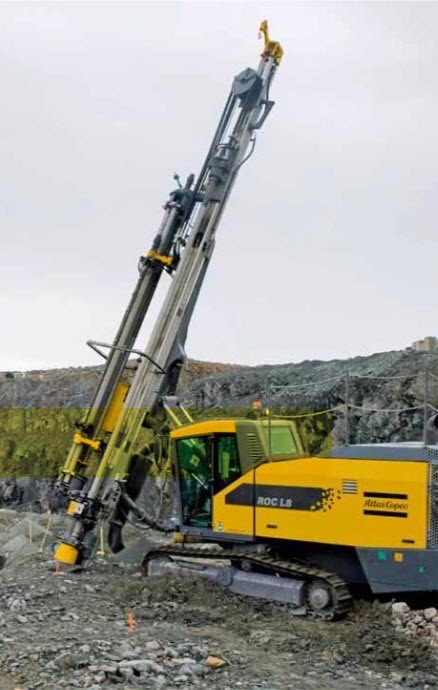
While the previous drill employs a down-the-hole hammer to apply energy to the bit, this one is a top-hammer drill, i.e., the energy source for the bit, at the top of the drill string. That means the “pounding and rotational” action has to be transmitted through the drill string to the bit. The biggest disadvantage of this approach is the loss in accuracy. The drill string tends to travel in a large helical track with the top hammer, and this causes the drill bit to “wander” off the desired location of the hole.
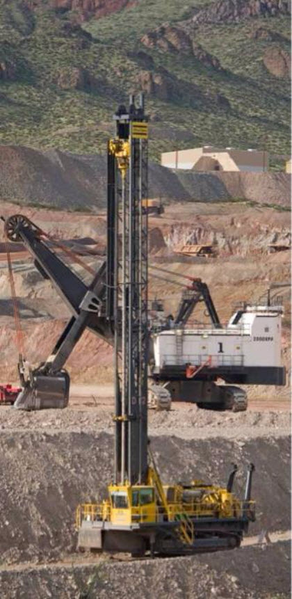
If these drills are going to be used underground where the headroom is limited, the mast is not as high but otherwise the drill is similar. While the accuracy of hole location is most always important, in some underground applications, it is crucial. In those, a down-the-hole hammer will be used.
Vertical or inclined holes are commonly required in surface mining, and sometimes in underground mining. It is very likely that horizontal or nearly horizontal holes will be required in underground mining, as well as overhead vertical or overhead angled holes.
The dual boom jumbo drill is designed to drill horizontal or inclined holes at angle off of the horizontal. The depth of these holes is typically limited by the application and is on the order of 15’.
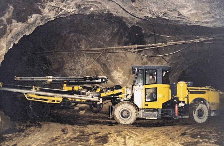
Ring or fan drilling and longhole drilling are characteristic of a few underground metal mining methods. The holes may be 150’ or long, and must be drilled to precise depths at the exact design angles. Drills to accommodate these requirements employ computer control to achieve the required accuracy, as do more and more jumbo and other drills being used in production operation. A typical drill is shown here. Note the remote operating station for the drill operator.
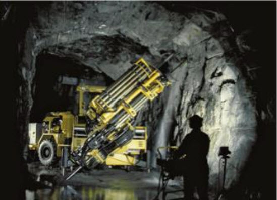
This diagram illustrates the drilling pattern required in a sublevel stoping mine. Notice the layout of the holes. What do you think would happen if a hole was started, but the angle was off by a few degrees? Or what if a particular hole were drilled to 128’ instead of the designed length of 135’? Intuitively, I am sure you can imagine that it will affect the performance of the blasting, and you are correct. We’ll talk more about this when we cover blasting, but for now, please recognize that productivity, cost, and safety are adversely affected by less-than-optimal drilling practices.
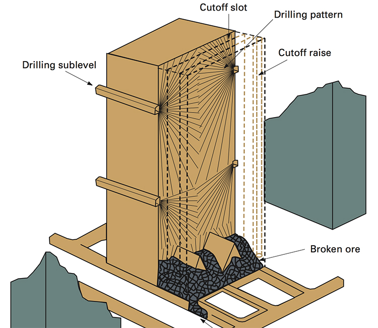
Finally, we should close our overview of drills with the handheld “jackleg” drill. In years past, these were used instead of jumbo drills in hardrock mining and for ground control applications in coal and metal/nonmetal mines. The size hole depended on the cylinder bore of the drill, as they were powered by compressed air, as well as the size of the drill bit. Hole sizes ranged from approximately 1” to 4”. Depending on the size, and consequently what the drill was used for, they were given names such as drifters or stopers. They are only used in modern mines for very specialized functions, requiring a few holes on occasion, here or there. Unfortunately, you will find them in widespread use in the underground mines of lesser-developed countries. I say unfortunately because they are brutal to use. Although much of the weight, around 75 lbs., is supported on the jackleg, the miner has to apply the thrust, i.e., pushing the drill bit into the hole. That alone is hard work. They are very loud, there is bone-jarring vibration, and they can produce dust-laden air and that along with the oil mist from the compressed air creates a respiratory hazard. Teams of miners would stand all shift-long operating these drills. Often they were paid based on the production that they achieved, and 15 years ago in the western U.S., one of these miners could easily earn $60-80 thousand dollars per year… but they earned every penny of that!
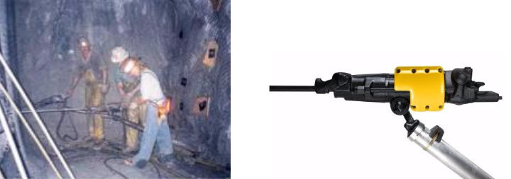
The practice of loading sticks of dynamite has all but disappeared from modern mining. Safer and more economic practices utilize explosives that are pumped, gravity-fed, or pneumatically blown into the hole. That’s not to say that we never use packaged material, because we do, and we’ll look at that when we discuss explosives and blasting practice. The vast majority of blasting, however, is accomplished with powders, gels, or emulsions that are bulk loaded.
Explosives Loaders
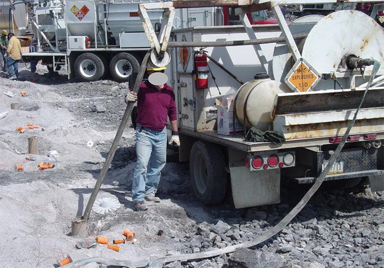
The truck below is used in surface mining. It carries the materials to mix the explosive at the hole, and the equipment to place the explosive into the hole. Such an arrangement can be found in some underground mines as well. In this example, the explosive is being pumped into the hole.
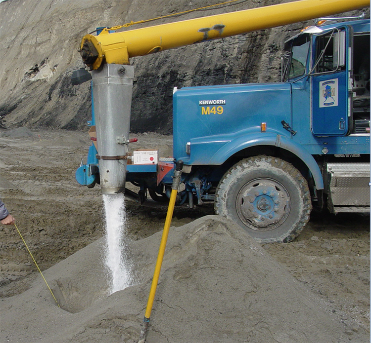
In a mine in which the height of the active mining face is on the order of 15’ to 60’ feet, you will see equipment like this. The boom allows the blaster, standing in the basket, to reach each hole, insert a hose into the hole, and then load the explosive. In this picture, you can see the yellow tank that contains the blasting agent. There is a second tank on the other side, which is obscured from view in this photo. These tanks are known colloquially as “powder monkeys.”
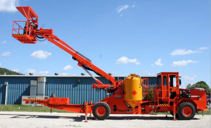
Rippers
Rippers are dozers that have been equipped with one or more large drag bits. These are pulled through the ore as the dozer moves forward. Typically, they break up the top 6” – 18”, depending on the mechanical properties of the ore. Rippers are not very common because they are suited to few deposits. Occasionally, I’ve seen them used in soft high calcium limestone and in coal, but there are other examples. In the picture here, this ripper (seen at the back of the image) has three large drag bits.
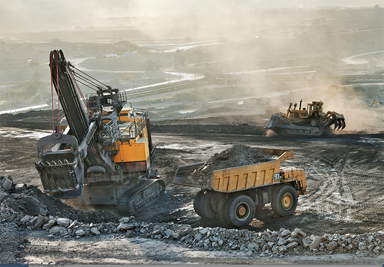
5.1.1b: Loading, Draglines, Shovels, and Hydraulic Excavators
5.1.1b: Loading, Draglines, Shovels, and Hydraulic Excavators
You’ll recall that the production cycle for harder ores is drill-blast-load-haul; while for softer ores, it is excavate-load-haul. I am emphasizing load because I want to talk about the equipment used for loading. In harder ores, the material is broken free of the orebody by drilling and blasting. Once it is freed, it usually must be loaded into something so that it can be hauled out of the mine. In softer ores, if a ripper is used, the broken ore will require loading. In softer ores, it is often practicable to free them from the orebody by digging or excavation, without the need to drill and blast. Once freed, the ore is usually loaded into something so that it can be hauled out of the mine. By the way, I am using the word something to describe the haulage out of the mine. I’ll be more specific shortly when we look at haulage.
The reason for this quick review of the difference in production cycles is because the equipment used in loading harder ores is sometimes used for both excavating and loading softer ores. I want you to be aware of this now so that you are not confused when we encounter this with certain pieces of loading equipment.
Draglines
Draglines have the ability to excavate huge quantities of material and then to place that material at quite a distance from the dragline itself. Here are some of the more important characteristics of draglines.
- The drag bucket is filled by pulling (dragging) the bucket towards the dragline.
- The dragline can only dig at a level below the level at which the dragline is sitting.
- The drag bucket is outfitted with “teeth” to aid excavation, but even so, it is only effective in softer materials or materials that have been blasted.
- The size of the dragline is based on the capacity of the drag bucket. A 15 yd dragline has a bucket capacity of 15 yd3. Typically draglines are in the range of 60 – 150 yd. The largest one ever built had a bucket capacity of 220 yd3. It could fill the bucket, swing it to the dump point nearly 300’ from the machine, dump the bucket, and return to begin the cycle over again in 45 seconds!
- The reach of the dragline determines the distance from the machine that material can be dumped. The maximum reach is approximately 450’.
- The weight of the dragline is so great, approaching 8000 tons in the larger units, that crawler tracks are used on only the very smallest draglines, and instead, they sit on two large “shoes” to distribute the weight. The shoes are attached to powered eccentric cams that allow the dragline to walk as mining advances.
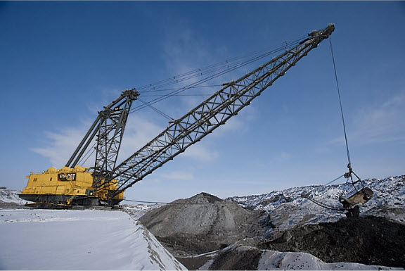
Draglines are commonly used to remove the overburden, also known as stripping, in open cast mining. In many cases, the overburden is drilled and blasted to facilitate removal by the dragline. Occasionally, the dragline will be used to remove the ore as well.
Shovels
Shovels have the ability to load large quantities of material, but less than draglines. A major difference between a shovel and dragline is that a shovel loads material at the same level as the shovel is sitting up to the height of the shovel’s boom. Here are some additional characteristics of shovels.
- The shovel’s dipper is filled by pushing the dipper into a bank of material. This action is known as crowding.
- The dipper is outfitted with “teeth” to aid excavation, but even so, it is only effective in softer materials or materials that have been blasted.
- The size of the shovel is based on the capacity of the dipper. A 12 yd shovel has a dipper capacity of 12 yd3. Typically, shovels are in the range of 10 – 90 yd.
- The digging height of the shovel is determined the size of the boom.
- Shovels are mounted on large crawler tracks, to facilitate movement into the bank, known as propelling; as well as to allow the shovel to move to the working faces or banks.
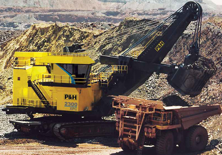
Large shovels are used for overburden removal, and in this application are known as stripping shovels. Perhaps more commonly, they are used to load ore into trucks. The relationship of key shovel parameters is illustrated in this diagram. Also, I’d like you to take notice of the wire ropes that are used to control the boom and the dipper. This is the original configuration for shovels. Over the past three decades, a modification of the shovel, using hydraulics cylinders instead of wire ropes, has become increasingly popular. Let’s take a look at it next.
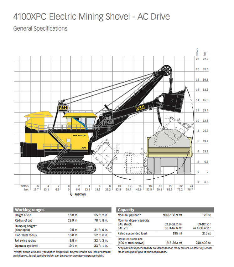
Hydraulic Excavators
This class of loader had its origin with machines that looked like this. These excavators had the advantage of being able to excavate or load below or above the level at which the machine is sitting. They also have the ability to be rather selective in what they remove.
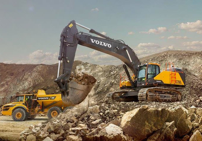
These excavators have gotten much larger over the years and have buckets of 40 yd3 or more, and a reach of 60’ or more.
The wire ropes on electric shovels have been replaced with hydraulics, and this has led to hydraulic excavators that look like this, and are often called hydraulic shovels. By replacing the wire ropes, additional degrees of freedom can be incorporated into the machine, resulting in better performance.
5.1.1c: Wheeled Loaders, Scoops and LHDs
5.1.1c: Wheeled Loaders, Scoops and LHDs
Wheeled loaders are mobile and maneuverable, and commonly found in surface and underground mining applications. The bucket typically ranges in size from a few yd3 to 10yd3. The high-lift linkage allows loading of the largest haul trucks available. These loaders are capable of digging soft and unconsolidated materials but are most commonly used for loading material that has been blasted. Chains are often put on the tires to increase the traction available, which allows the bucket to push more efficiently into piles of broken rock. In everyday use, they are often called loaders, rather than wheeled loaders.
Here we can see a very common use of the wheeled loader.
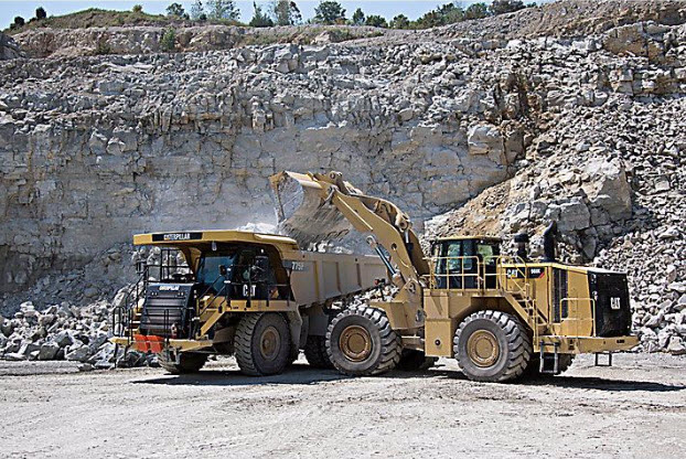
Next, let’s take a look at some loaders that are used exclusively underground. The amount of clearance available underground can be quite restrictive. While some underground mines will have openings that are approaching 100’ in height, less than 10’ is much more common. The equipment designed to operate in these confined spaces has to be designed quite differently to fit into these spaces and still be capable of doing something useful.
Scoops and LHDs (Load-Haul-Dump)
There are some differences between scoops and LHDs, but for the purpose of this discussion on loaders, we are not going to differentiate between the two other than to note that scoops are more likely to be used strictly for loading ore into an underground mine truck in metal mining, and that they are often used for moving supplies around in underground coal mines.
These machines are designed with a low profile to function in confined spaces. Moreover, they are often articulated, i.e., the machine is split into two parts and connected with an articulating joint. This allows the machine to turn and maneuver in tighter spaces. The scoop loader shown here illustrates the concept quite nicely. At less than 3-1/2’ wide, 6’ high, and 16’ long, it would easily fit inside of the bucket of many surface loaders! The bucket capacity of these machines ranges from just under 1 yd3 to 4 or 5 yd3.
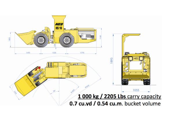
Here is a picture of a typical LHD, which stands for Load-Haul-Dump. These machines are commonly used in underground metal mining and they push into a pile of broken ore (load) and then they haul (transport) their load to a dump point. The haul distances are relatively short – typically less than a 1000’, although this can vary. This LHD is available with bucket capacities ranging from 10 to 15 yd3.
When we talk about the underground metal mining methods, you will see the importance of LHDs in those operations.
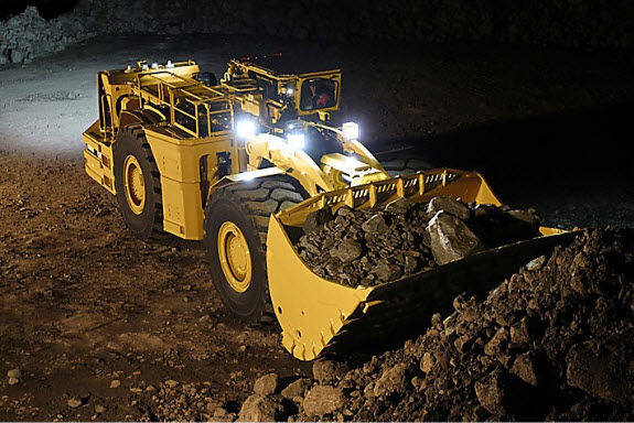
This brief introduction to loaders is by no means exhaustive. There are still some legacy devices in use – overshot loaders and slushers, for example, in metal mining. However, here, we have covered the devices that account for virtually all tonnage produced in modern mining systems. This also brings to a close our discussion not only loaders but also ore winning, more or less. Wait a minute, more or less? Well mostly more… however, we have not talked about an important class of ore winning machines known as continuous miners, road headers, and shearers. We’ll do that in the next lesson. For now, we’re now ready to move into materials handling – the last unit operation in the production cycle of drill-blast-load-haul for hard rock or excavate-load-haul for soft rock.
5.1.2: Materials Handling
5.1.2: Materials Handling
Materials handling is concerned with how we move (haul) the mined material out of the mine to the processing plant. Before looking at specific haulage options, we should talk about a few overarching concepts. The first is intermediate haulage.
At the working face, i.e., where the ore is being freed from the deposit, we are going to load the ore into some type of haulage. If we are in a surface mine, it is likely that we’ll load the ore into a truck, which will haul the ore the entire way to the plant, dump it, and then return to the face for another load. If we are in an underground mine, it is likely that the material at the face will be loaded into a haulage vehicle and then transported to an intermediate dumping point. From the intermediate point, a different haulage device will be employed. Sometimes, there could be even another subsequent intermediate device. As an example, assume we have a mine in which LHDs are used to load out the ore at the draw point (face) and transport it to a dump. The dump point is at an ore chute in the rock that funnels the ore to a lower level where it is loaded into rail cars, along with the ore from many other dump points. A train may pull these cars several miles out of the mine and to a processing plant. Or, the train may take the ore to a transfer point at the bottom of the shaft, where the ore will be dumped and transported in large ore skips (buckets) up the shaft to the surface. The choice of a specific type of materials handling is based on optimizing the overall process. Smaller and maneuverable equipment is best suited at the face, whereas larger capacity, but more permanent equipment may be indicated to move the material out of the mine. As we look at different mining methods, this will become even clearer.
Let’s identify the common choices for materials handling, to move material from the face to the plant.
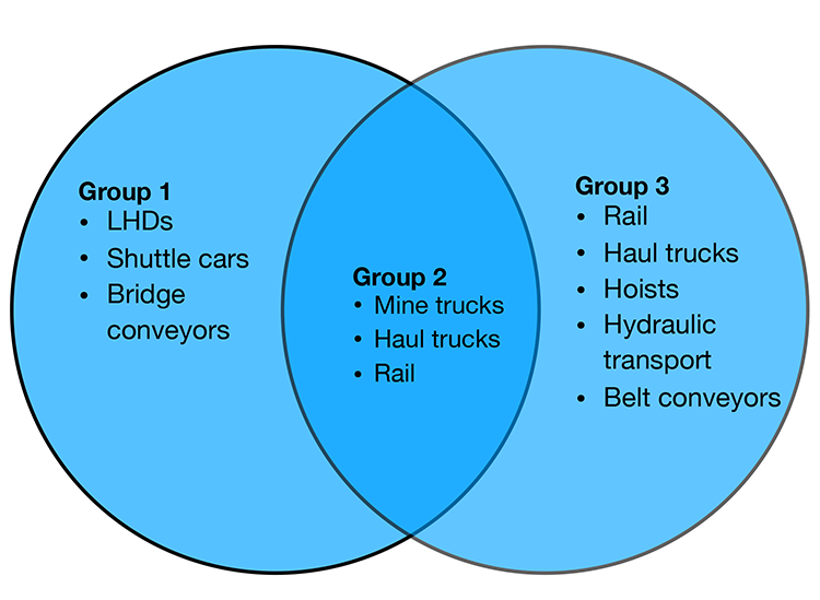
Click here to see a text description.
- Group 1
- LHDs
- shuttle cars
- bridge conveyors
- Group 2
- mine trucks
- haul trucks
- rail
- Group 3
- rail
- haul trucks
- hoists
- hydraulic transport
- belt conveyors
I’ve arranged them into three groups. The equipment in the first group is typically used for short haulage runs from the face to an intermediate dump or transfer point. The equipment in the third group is used to move the material out of the mine and to the plant. The equipment in the second group can fall into Groups I or III. In some instances, the equipment shown in Group II will be used to move the material directly from the face to the plant, whereas in others, it will be used to transfer the ore to an intermediate point. Again, the choice and rationale will become clearer as we learn about the requirements inherent to the different mining methods. Let’s look at the general characteristics of these materials-handling modes. We’ve already discussed LHDs, so let’s begin with shuttle cars.
5.1.2a: Shuttle Cars and Bridge Conveyors
5.1.2a: Shuttle Cars and Bridge Conveyors
Shuttle Cars
Shuttle cars are a low-profile intermediate haulage option used predominantly in underground coal and some industrial minerals mines. Ore is loaded into the shuttle car at the face, and then it trams a relatively short distance, dumps its load, and returns to repeat the cycle. Shuttle cars are manufactured in different sizes to work in very thin seams of less than 36” to high seams, greater than 72”. The capacity is dependent on the size, but a typical capacity is 6 – 10 tons. The shuttle car normally dumps into a feeder-breaker, which crushes any large lumps and feeds the load onto a conveyor belt. Variations of the shuttle car include ram cars and haulers.
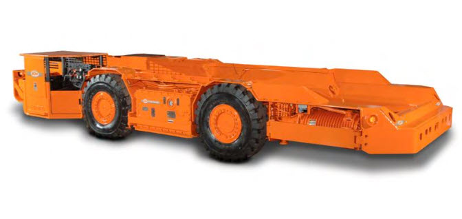
Bridge Conveyors
Bridge conveyors are belt conveyors that are designed to move material directly form the face to a final point, e.g., a spoil pile in surface mining, or a transfer to a main conveyor in underground mining. Unlike main-belt conveyors, which are semi-permanent, bridge conveyors are designed to be easily maneuverable, to keep up with the active mining face. Looking at this bridge conveyor, known as a flexible conveyor train, you can see the hopper where ore is loaded. There is a feeder in this hopper that meters the ore onto the rubber conveyor belt. Note that the belt can go around corners. These have found limited application in underground coal and salt mines.
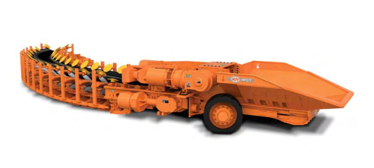
Here is an example of a conveyor being used to transport spoil (overburden) directly from the bucket of an excavator to spoil piles.
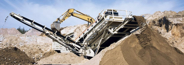
5.1.2b: Mine Trucks, Haul Trucks, and Rail (Trains)
5.1.2b: Mine Trucks, Haul Trucks, and Rail (Trains)
The distinction between haul trucks and mine trucks is subtle but important. Mine trucks are generally designed for underground use in more confined spaces. They will have an articulating joint to allow turning in a tighter radius. The capacity will also be less because of clearance restrictions. Nonetheless, capacities of 15 to 60 tons are common. These mine trucks, as pictured here, are commonly used in underground metal and nonmetal mining, and they are as likely to transport the ore directly from the face to the plant as to transport to an intermediate transfer point.
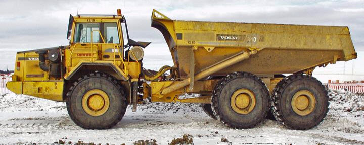
Haul Trucks
Haul trucks are designed to transport larger loads than mine trucks, and in some underground mines where there is sufficient room, you will find haul trucks. For example, in a salt mine where a 90’ thick seam is being removed, you can fit a large truck of 60–100-ton capacity, although, in underground metal/nonmetal mines, a size of fewer than 60 tons would be more common.
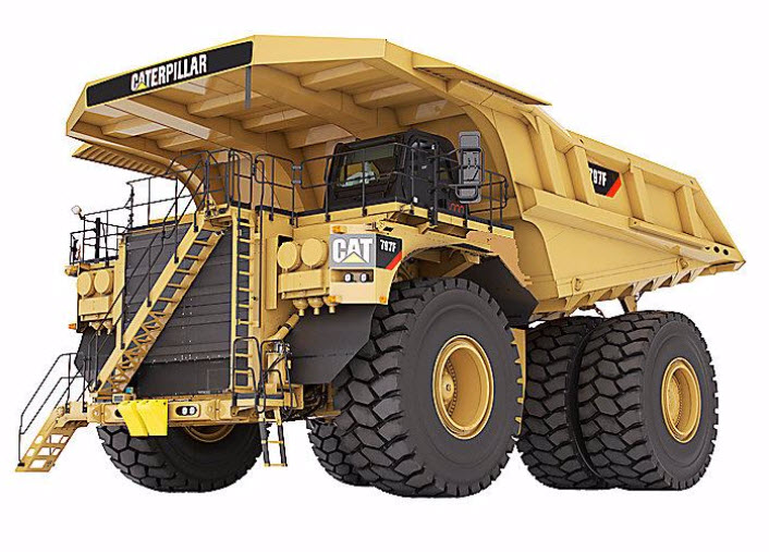
This haul truck holds nearly 450 tons and is in use at a surface coal mine in the Powder River Basin.
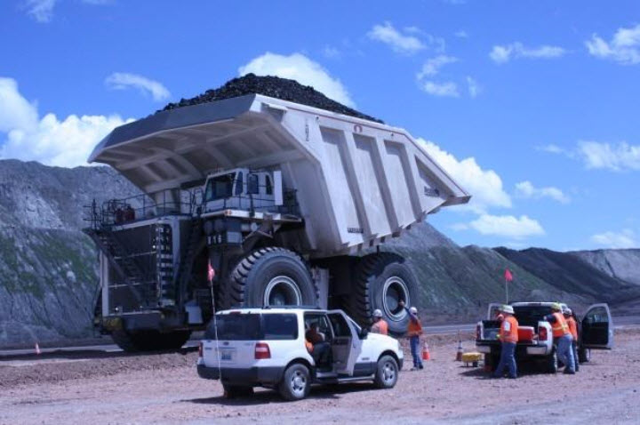
Rail (Trains)
Rail haulage was once very common in underground mines, and even in some surface mines. It has the advantage of being able to transport large loads at a low cost. It has fallen out of favor because it has inherent problems that make it unsuitable for many of today’s high production mining systems. Nonetheless, it is still used. In modern coal mines, for example, rail haulage will often be used to transport equipment and supplies, whereas conveyors will be used to transport the coal. The reasons for this will become evident when we look at batch and continuous operations in the next lesson. Rail can be used as an intermediate form of haulage, or as the means to transport the ore out of the mine to the plant. The locomotives and cars used may be of lower profile, like the one shown here.
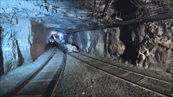
5.1.2c: Hoists, Hydraulic Transport, and Belt Conveyors
5.1.2c: Hoists, Hydraulic Transport, and Belt Conveyors
Deep underground mines may be accessible only through a shaft that is sunk from the surface to the working levels of the mine. Not only will all workers and supplies access the mine through the shaft, but also all ore will have to come out of the shaft. This is accomplished by hoisting systems. Three major components of a hoist are the skip, which holds the ore and is attached to the winder on the surface by wire ropes, the headframe and the hoist winder (winch and drum). The headframe supports the sheave wheel over which the wire rope is connected to the skip. As the drums in the surface hoist house wind the rope onto the drum, the skip is pulled to the surface, where it is dumped.
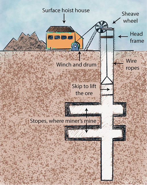
The winder is shown in the first picture below, the bottom headframe in the second, and the bottom dump skip in the third. Often a different type of hoist from the one shown is used, which allows a skip to be connected at the bottom and the top of the shaft so that as the one is being unloaded, the other is being loaded. A skip typically holds up to 50 yd3 of material.
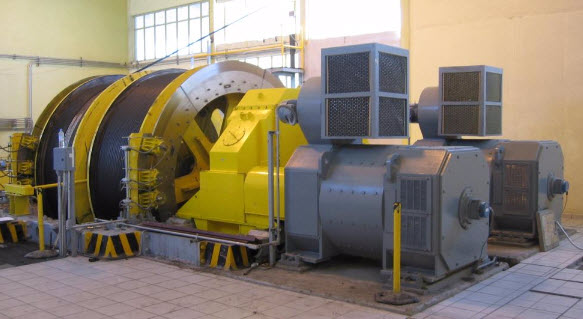
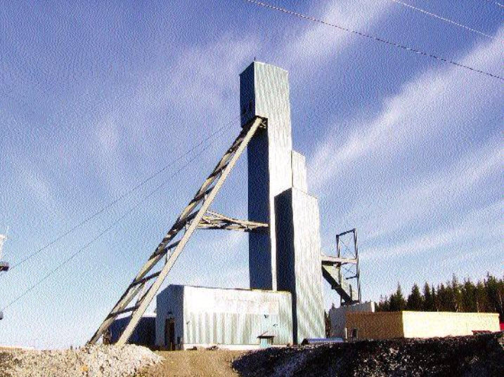
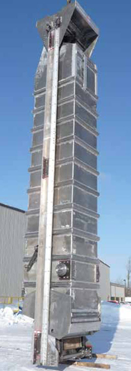
Hydraulic Transport
Hydraulic transport, often known as a slurry transport system, is used in limited circumstances. The ore is mixed with a fluid, e.g., water, and pumped from the mine to the processing plant. It is an energy-intensive system and is best suited to a limited class of ores such as phosphate, which is already mixed with water in the mining process, or other ores obtained from hydraulicking or dredging. The system is straightforward, consisting of high horsepower slurry pumps every few miles and a large diameter pipe, greater than 2’ in diameter.
Belt Conveyors
Belt conveyors are the workhorses of modern mines, both surface and underground. The belt conveyor consists of the belt, which is constructed of multiple plys to provide the required strength and wear resistance; the belt is constructed into a closed loop and stretched between a head and tail pulley; the belt is supported with idlers between the head and tail, and they maintain the appropriate trough shape as well as support the weight of the material in the belt. The head pulley is connected to a motor to power the conveyor. These belts range in width from a few feet to more than 8’, and can transport thousands of tons of ore per hour. Although each belt is of limited length based on mechanical constraints, they can be combined into long runs by constructing transfer points to allow one belt to dump onto another. In this fashion, complex networks can be assembled. Here is an example from a surface mine.
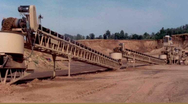
Many years ago, the incline angle of the conveyor was limited by the angle of repose of the ore being conveyed. If this angle was exceeded, the material would begin to slide down the conveyor and would no longer be conveyed upward. Modern designs and significant material improvements now permit belt angles up to 90°, as shown in the second picture.
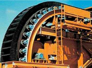
Lesson 5.1 Summary
Lesson 5.1 Summary
There is, of course, much more that we could say about materials handling systems. Indeed, we have an entire course on their design! For our purposes here, this brief overview will help us to understand the sequence of operations in the mining methods that we will be studying.
Knowledge Check
In Lesson 5.3, we’ll take a look at the difference between batch and continuous operations, and the evolution of the so-called “continuous mining systems.” However, before talking about that topic, we will look at auxiliary operations next.
Lesson 5.2: Auxiliary Operations
Lesson 5.2: Auxiliary Operations
In the last lesson, we learned that the process of exploitation reduces to two fundamental operations: winning and materials handling. Further, we defined the basic production cycle in terms of unit operations, as follows:
Harder Materials: drill, blast, load, and haul
Softer Materials: excavate, load, and haul
I noted that there is one other category of common operations known as auxiliary operations, which support the production cycle and are essential to it. Auxiliary operations are repeated over and over again; and as with the unit operations, the specifics of the auxiliary operations will vary by mining method and the characteristics of the orebody. In the last lesson, I gave a few examples of auxiliary operations, including ground control and electric power.
In this lesson, I want to provide additional information and examples of auxiliary operations, including the equipment used in these operations. The auxiliary operations are not only complementary to the unit operations, but are generally essential to the completion of the mining cycle. As such, it is difficult to say that some are more important than others. So, if we want to see they are all equally important, then I would add that a few of them are first among equals! Those would include ground control, power, and ventilation.
5.2.1: Ground Control
5.2.1: Ground Control
An Overview of the Requirement
One of the more important and defining characteristics of mining engineers is their ability to design structures in earth materials. Few appreciate the incredible challenge this presents. Consider that if we want to design a building, we can go to a handbook and find the exact mechanical properties of our building materials, whether they are steel beams, lumber, or concrete. Important engineering challenges may remain in the design of the building, but at least we know the properties of our building materials.
…not so when we are constructing something in the crust of the earth. Sure, we can conduct lab tests and that is helpful, but significant uncertainty remains throughout the property in many cases. Even when we have a well defined material, a limestone for example, it may have structural defects due to geologic processes that result in fractures, joints, and so on. Once past the hurdle of knowing the properties that we are working with, we have to work with them! That is to say, some of the materials may be “inferior” or “substandard” to use construction terminology. But, in our case, we can return those “inferior” rock structures to the maker, and demand new ones with better properties. And here lies what can be a daily challenge for the mining engineer: maintaining a stable and safe rock mass to allow mining of the valuable commodity.
Whether we are designing and operating a surface or underground mine, this will be a challenge of varying degrees. In the surface mine, we are concerned with a failure of the slope or the highwall. If it is too high or too steep or if there has been an influx of groundwater, or… we can have a failure. The failure could kill all of the workers in the area, destroy or bury the equipment, and result in costly production delays. In an underground mine, we develop a series of openings to access and exploit the deposit. If any of those openings cave in, it can have disastrous consequences for the miners and the overall viability of the operation. The art and science of safely designing structures in the earth is captured in the term ground control. The coursework in engineering mechanics, strength of materials, and rock mechanics will give you a solid theoretical foundation, and then courses in ground control along with years of experience will enable you to succeed in this endeavor.
I think you are beginning to appreciate the importance of this auxiliary operation, which is an intimate companion with the unit operations of the production cycle. Here in this course, we’ll talk about how the ground conditions affect the mining methods and the sequence of operations, and some of the practices that are used to “control the ground” to prevent unwanted and unexpected failures.
Ground control is achieved in part through the design of the structures. For example, the engineer will design spans that won’t fail or determine the angle of the highwall to reduce the risk of a slope failure. We’ll leave the design component of ground control to other courses. Operationally, after the design, ground control is achieved in part through the use of various technologies. Uses of these technologies are an ongoing part of the production cycle, and as such are of special interest in this lesson.
Cyclical Practices
After drilling and blasting, the integrity of the surrounding ground will be inspected. This will happen prior to loading to ensure that miners engaged in the loading operation are not put in danger. This check is imperative in underground mining, and in many surface mining operations. There may be pieces of rock that have cracked but hung up, and they may fail without warning. Or there may be loose pieces that could fall. Thus, the inspection will be the prelude to scaling or barring, i.e. the act of knocking these pieces free. In a low seam mine, with minimal need for scaling, this may be accomplished with miners using a steel bar with a chiseled edge. When it is impossible to reach the area that needs scaling, then equipment will be used. Here is a scaler that is found in metal/nonmetal mines; and primarily but not exclusively in underground mines. It has a telescoping boom to reach high places and a pneumatic hammer to release any worrisome pieces of rock. The operator remains inside the cab, which provides protection from falling material. Notice also the dozer blade on the front. It is used to push a fallen material out of the way.
Ok, so this inspection and scaling represents the first auxiliary operation.
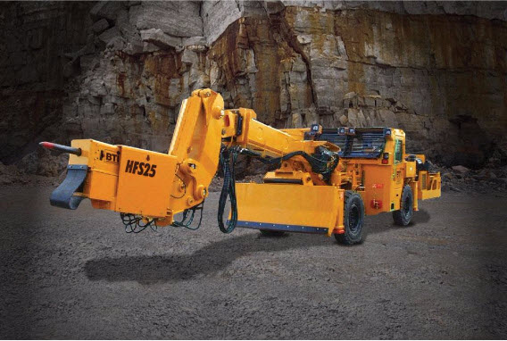
Once the area has been scaled, it will be safe to bring in equipment for loading and hauling in some mines – mines with competent rock that is not going to cave. In some mines, it is necessary to take further steps to improve the opening to ensure that the rock strata is not going to fall onto the miners, and this must be done before miners work in the freshly mined space. If additional reinforcement of the rock is required, then that will be the second auxiliary operation.
We’ll take a look at some of the equipment used to reinforce the rock, but first, a quick tutorial on the options for adding additional support to the ground.
5.2.2: Active and Passive Ground Support
5.2.2: Active and Passive Ground Support
Ground support can be active or passive. If we take actions that actually increase the strength of the rock, then we are providing active support. On the other hand, if we do nothing to increase the strength, but instead we take an action to prevent the rock mass from falling, then we are providing passive support. There are valid applications of both categories of support. Let’s look at an example. Actually, this is a really important example!
The rock strata overlying a tabular deposit are often somewhat weak. They may consist of relatively thin layers of a weak rock. These layers, which may be a few inches to a few feet in thickness, may also have partings between them. These partings may be very thin, and very weak. Now, what is going to happen when we remove the ore from underneath the overlying rock mass that I just described?
Did you ever have a long bookshelf made of wood – wood that is not very thick? What happened when you place a full load of books on the shelf? It begins to sag in the middle, right? It may not have happened immediately, but over time, it sags in the middle. A similar mechanism is at play in the mine strata of our example. All of the weight of the overlying rock layers is pushing down. You removed the ore from underneath the strata, so you now have a long unsupported span of relatively weak rock layers. The rock layers begin to sag, and before long the lowest layer will separate from the others, and fail. When it fails, it will break apart and fall to the ground. Now, the layer immediately above the one that just failed will sag, and it too will fail. This will continue until the rock mass reaches some equilibrium. This is an unacceptable outcome! We’ll never make any money at this mining business if we can’t support the openings that we create! So, you must prevent the initial failure. What are your options?
As with the bookshelf, you could place a support in the middle of the span to support the load and prevent sagging. In our mine, we could set a timber post into place, and it would prevent the failure. This is an example of a passive support. Placing timber posts, steel arches, and so on is a time-honored means of supporting the rock and preventing failures. There are some drawbacks, however. If we’re mining a 6’ thick coal seam, we can set a 6’ post. What if we are mining a 60’ seam of limestone? Finding, handling, and placing a 60’post would be a supremely daunting task, and clearly not practical! Even when it would be easy to set a post, there can be unacceptable drawbacks to the practice.
Let’s think about a basketball arena like Bryce Jordan Center. The roof of that building spans a large area, and that roof needs to be supported. Assuming that we can obtain timber posts of sufficient length, why not set them across the width of the building, perhaps every 20’ or so to support the roof? For starters, it would make for an interesting new twist to the game of basketball as the players dodged the posts on their way to the basket! Again, not very practical, and that is the drawback in the mine as well. Instead of basketball players, we have large equipment moving around and between the working areas. Thus, in many locations, this kind of passive support is inconsistent with production needs. While passive support is an appropriate control strategy in many instances, we need an alternative for when it is not.
Roof Bolts
One of the most prevalent and effective means of providing ground support is an active support known as a roof or rock bolt. Remember the failure in the layered strata of our example mine? What if we were to clamp several of those weak layers together, forming a “laminated beam”? Beams are very strong, and, indeed, by clamping these layers together, we have strengthened the rock mass, and it will be able to support the weight on it without failing. Many of you may have seen laminated beams used in building construction. Several layers of thin and relatively weak plywood are glued together, and the result is beam with superior properties to a solid piece of wood of the same thickness.
In our case, we can’t access both sides of the rock mass to clamp the layers together, as is the case when they fabricate laminated wooden beams. Instead, we use a rock bolt, as illustrated in this diagram.
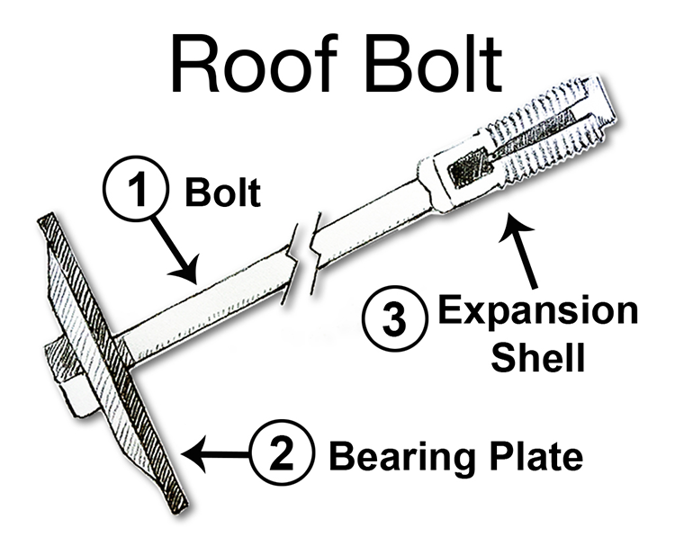
It works as follows. A hole is drilled into the rock mass that is to be supported. Next, the roof bolt is inserted into the hole. Then the bolt head is rotated, which causes the expansion shell to expand into the surrounding rock, locking it in place, and as the bolt rotates, it draws in the bearing plate. As a result, the layers between the expansion shell and the bearing plate are compressed tightly together, forming a beam. For this to work, the expansion shell must be anchored in competent rock. Sometimes, this can be done over 4’ and other times, 6’ or more. The length of the bolt is chosen with this in mind. The diameter of the bolt, which is between ½ - 1”, is based on the required tensile strength of the bolt, which is determined by calculating the weight of overlying rock that each bolt will have to support. In the future, you will learn how to size rock bolts. At this time, the takeaway message is:
- bolting is an active support because it is increasing the strength of the rock mass to prevent failure by clamping weak layers together to form a strong beam; and
- bolting is the most prevalent means of ground control in the majority of underground mines, and also in certain surface mines.
Under difficult conditions, we can place a skinny bag of resin, i.e., a strong glue, into the hole with the bolt; and then, as the bolt spins while it is being tightened, the bag will break and the resin will be mixed and will completely fill the hole around the bolt. Moreover, this resin will plug cracks and fractures in the rock in the immediate vicinity to further enhance the bolt’s holding power.
Here is a picture of roof bolting machine, commonly known as roof bolter or simply, a bolter. If you look closely, you will see the drill in front of the operator. Notice the attachment point to the machine at the bottom, i.e., the chuck. As the hole is drilled, that chuck assembly will move up towards the collar of the hole. After the hole is drilled, the operator will place a bolt in the chuck, insert it into the hole, and tighten it. The machine has plenty of space to store a supply of bolts along with the drill tools. You will also notice hydraulic canopies pressing into the top or “roof” of the mine opening. Those are passive supports to ensure that the top does not fall down while the bolter operator is installing the roof bolts.
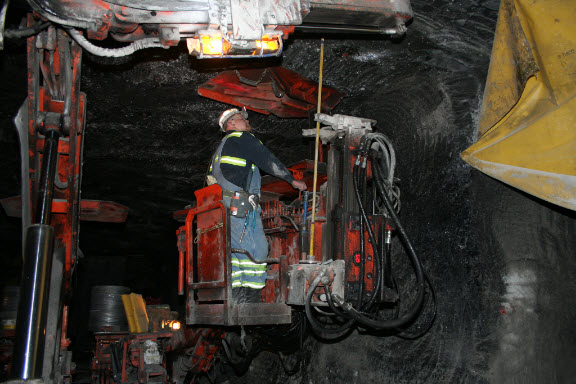
In so-called large opening mines, where the distance between the bottom and top of the mine opening might be 20 – 30’ or more, a slightly different configuration is required, as shown here. The operator would stand in the “cherry picker basket" and operate the drill and bolter.
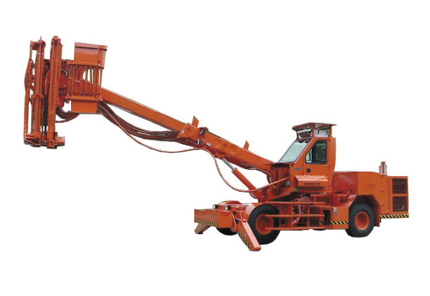
Cable Bolts
Sometimes, we need a bolt that is much longer than 4 – 6’. Remember, I said that for the bolt to achieve its purpose, the anchor must be in a competent rock layer. What if that layer is 15’, or 50’ or even 100’ above the opening? A bolt of such lengths would be impractical. Instead, we use a cable bolt. A reel of specially constructed steel cable is stored on a cable-bolting machine. A hole of the required length is drilled, an anchor shell is attached to the end of the cable, and it is fed to the end of the hole. An anchor plate and tensioning bolt is affixed to the end, and it is tensioned in some fashion as a traditional rock bolt. One difference, however, is that concrete grout will be pumped into the hole as well. Here is an example of a cable bolter. If you look closely, you can see the cable routed from the spool on the rear of the machine, up over the machine, and to the front where it will be inserted into the hole. The carriage housing the drill steel and the drill are also visible at the front of the machine.
Shotcrete
Shotcrete is another active support of note. Pillars of rock or ore are often left standing to help support the overlying strata, and only the ore between the pillars is recovered. The pillars can be under a lot of stress, and in some cases will begin to fail. The outer layers tend to crack and spall off, until the pillar is much skinnier and more likely to fail. The spalling of the outer layers can also present an immediate safety problem. One means of active support is to spray a Shotcrete onto the pillar. The Shotcrete may be cement or polymer mix, and fibers of various materials may be embedded in the mix. Thicknesses of an inch or more would be typical. Once the Shotcrete has dried, or really cured, it is quite strong and provides a confinement stress on the pillar. Sometimes the top surface of the span will be shotcreted as well.
Here is a picture of a shotcrete operation in progress. You may be able to see the nozzle at the end of the boom, the mixing tank, and the dry feed hopper, and water line on the equipment. The other line is an electric power cable. The hose and cable reels provide sufficient mobility to the machine to allow it to move freely among working places, at least until the limit of the hose and cable are reached. Then, it will be necessary to advance the electrical and water supplies. Advancing utilities, such as electric power and water, is another important auxiliary operation that we will discuss shortly.
We’ve covered the majority of the ground control technologies with this brief introduction to active supports such as roof bolts, cable bolts, and shotcrete; and passive supports such as timber or steel posts and arches. There are others, but this group is illustrative. There is one more ground control technique that deserves a brief mention before we move on to other auxiliary operations, and that is backfilling.
Backfilling
Backfilling is the process of adding support to a mined out area by filling it with backfill, i.e., waste rock, tailings, or a mixture of cement and tailings or waste rock. As you might suspect, the time and cost to backfill is very expensive. Nonetheless, it is a part of the cut and fill mining method, in which we routinely mine a slice of ore, backfill it, and mine out the next slice, and so on. We’ll talk more about backfilling when we discuss this mining method. For now, you should simply be aware of backfilling as another ground control practice.
Also, I want to be clear that while the ground control challenge in underground mining is generally far more complicated than in surface mining, ground control practices including inspection and scaling are part of surface mining, and the use of rock bolts is part of some surface operations.
After this brief tutorial of ground control, you’ve probably forgotten how we got started on this discussion in the first place! Ground control is a critical auxiliary operation, and although we usually speak generally of ground control, in total, we’ve now seen that there are three components: inspection, scaling and installing ground support. Depending on the mining method and the competency of the rock, the activities associated with ground control may occur at differing time points in the production cycle.
5.2.3: Electrical Systems
5.2.3: Electrical Systems
The power sources for mining equipment are compressed air, diesel, and electric. Most mining equipment today is powered with either diesel or electric. Diesel provides more mobility because there is no need to be tethered to an electrical cable. On the other hand, the exhaust from a diesel engine creates challenges when used in a confined space, like an underground mine, and it requires a high level of regular and sophisticated maintenance. Electric has certain inherent advantages including the ability to provide a lot of power in a small space and no toxic emissions at the machine. Large equipment, such as draglines and shovels, as well as continuous miners, is usually electric. Diesel is favored for haul trucks because of the need to be untethered.
Nearly fifty years ago, there was an effort to replace electrically powered equipment with diesel engines. Eliminating the delays associated with the tether, as well as delays associated with inevitable failures of the tethers (cables) was easy to justify; and particularly so for mobile materials handling equipment. In recent years, the air quality issues associated with diesel particulate matter and noxious gases from the engine exhaust have caused some operators to transition back to electric equipment.
I should mention battery-powered equipment, given that today we are seeing more and more battery-powered vehicles on the highways. With battery power, the tether, i.e., the cable, is eliminated, and there aren’t the drawbacks associated with diesel engines. Unfortunately, it is difficult to pack sufficient energy into a battery pack to replace the “workhorses” of hauling ore and rock. Consequently, battery-powered equipment is used for utility vehicles, such as personnel carriers or scoops for hauling supplies.
The machinery associated with production will move throughout the mine over the mine life, and as this equipment makes its way through the deposit, it will be necessary to move the electrical power system along with it. Depending on the mining method, we may need to move power every few shifts, or in other cases, only every few months. Many of you have some familiarity with power systems found in towns – the substations, power lines, and so on. Can you imagine having to move and advance such a power system on a frequent basis? In many mining methods, that is all part of a day’s work! Of course, we’ve taken steps to make it more manageable. The substations and other equipment that have to be moved are mounted on skids, crawlers, or rubber tires to facilitate movement. Couplers are used to connect and disconnect components and cables. It’s manageable!
Of course, there are other electrical loads, some of which must be moved periodically, and others that are stationary and semi-permanent. These loads would include pumps, conveyors, and illumination. Even if the mining machinery is all diesel powered, it is likely that there would be other electrical loads that must be powered. Therefore, providing electrical power will be a necessary auxiliary operation for most mining methods used in surface and underground mining.
Here is a picture of a skid-mounted power center for use in an underground mine. You can see the high voltage cable going into the box. Inside, there is a transformer to reduce the distribution voltage, typically 4.16 to 15 kV, to the level required by the machinery, typically 480 to 995 V. On the other side of this box, outside of our view, there are couplers to connect the various loads. Protective devices for each outgoing circuit are built into the power center.
Here is a picture of a similar power center, which has just been built. Here, you can get a better view of each outgoing circuit. Each cable-connected load plugs into one of these circuits. The lid of the power center is removed only for maintenance purposes.
You might see a load center like the one in the following picture in a surface mine. Essentially, a shipping container has been mounted on a skid, and the required electrical components have been assembled inside the container. I’ve seen power centers in surface mines that have been built on railroad cars and old tractor-trailer beds, among others!
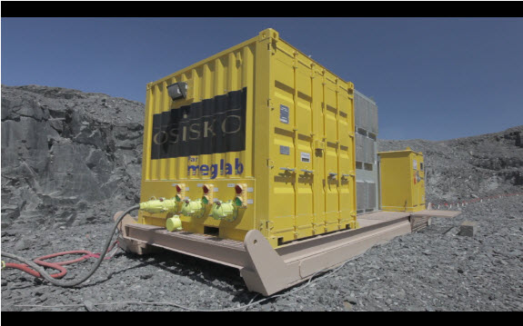
As I mentioned earlier, these power centers must be advanced as mining progresses. Often a “power move” will require adding additional high-voltage cable, or in some surface mines, adding additional poles and overhead lines. Some mining methods are more “electric-intensive” than others, and that also varies by commodity. Room and pillar mines in coal, salt, or trona, for example, are very power intensive, requiring significant infrastructure and frequent moves. Others, such as room and pillar mining in limestone or cut and fill mining in gold, require less electrical infrastructure and few moves. Nonetheless, providing safe, reliable, and timely power is a critical auxiliary operation in most mines.
5.2.4: Ventilation
5.2.4: Ventilation
Fresh air is required to provide oxygen and to carry away carbon dioxide. Large quantities of air are often required to dilute, render harmless, and carry-away dangerous dusts and gases. Methane is an explosive gas associated with coal deposits, among others. Sufficient air must be coursed through the coal mine to keep the methane concentration well below the lower explosive limit. Hydrogen sulfide, a deadly gas, forms under certain conditions in underground metal mines and must be diluted to render it harmless. Carbon monoxide and oxides of nitrogen are produced during blasting, and these toxic gases must be diluted and carried away before miners return to continue the production cycle. The concentration of respirable silica dust, i.e., dust small enough to become trapped in the lungs, is produced during mining and can lead to fatal lung diseases when inhaled over years of work. Accordingly, the allowable concentration of respirable dusts is heavily regulated and controlled, and providing sufficient air to carry away these dusts is important. We could go on with the examples, but you get the idea!
It is easy to understand the need to provide large quantities of air, sometimes on the order of several hundred thousand cubic feet per minute! It is not so easy to control that air, to get the right amounts to the different parts of the mine, and then to move the “dirty air” to outside of the mine. It takes significant engineering, and many control devices, to achieve the intended outcome. If you look, for example, at this plan view of a mine, below, you can see the many passageways. It resembles the streets and avenues of a city. Now imagine that you have one or two entry points for fresh air, as provided by fans, and you have a few exit points where the exhaust air is ventilated to the outside. All that you have to do is to make sure that the proper quantities are flowing in each of the “streets” and “avenues.” Further, you have to do this on an ongoing basis, since the layout of the mine changes from day-to-day as mining advances. No small feat…! Depending on the mining plan, you can build stoppings, i.e., solid barriers to divert air, you can hang curtains to divert air, you can install and adjust regulators to control pressure drops and the attendant airflows, and you move auxiliary fans and tubing to further direct airflows to where they are needed.
When we looked at ground control, we identified the importance of inspection, as the first step in that auxiliary operation. Similarly, with ventilation, there is a “check” that occurs as a prerequisite to certain unit operations. Gas measurements may be required as well as air quantity determinations. It may be necessary to adjust the ventilation system as a result of these measurements or to change the production plans until adequate ventilation can be provided.
Our discussion has focused on ventilating underground mines, and indeed that’s where most of the action is to be found. Interestingly, surface mines occasionally experience challenging ventilation problems. Some open pit mines, for example, are deep enough that temperature inversions can occur, in which air in the pit is trapped by a cooler and heavy layer of air near the top of the pit. The diesel fumes from the heavy equipment operating down in the lower levels of the pit can build up to dangerous levels. Utilizing artificial ventilation in this circumstance, whether the wind induced from the blades of a helicopter hovering over the pit or large axial vane fans, is essential to protecting the health of the miners and ensuring that production can continue.
Ventilation, as with ground control, is a crucial auxiliary operation.
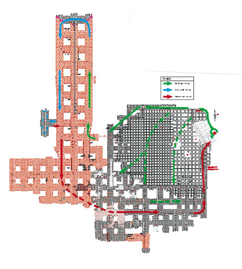
5.2.5: Maintenance
5.2.5: Maintenance
The level of maintenance required to keep the equipment operating properly and safely varies by the mining method and the particular equipment in use. Usually, the idea is to minimize breakdowns during a production shift and the need for emergency maintenance. Instead, preventive maintenance is practiced to reduce failures, and scheduled maintenance is planned for nonproduction shifts. In some mines, there will be two eight-hour production shifts followed by an eight-hour maintenance shift every day. In other mines, there will be two ten-hour production shifts, followed by a four-hour maintenance shift. And in yet other mines, a week of production will be followed with a weekend of maintenance.
The value of a minute is often underestimated by those just learning about the industry. Given the capital cost of mining equipment, and the cost of labor and so forth, a delay can easily cost hundreds of dollars per minute and exceed a thousand dollars a minute in certain circumstances. As such, maintenance is a critical auxiliary operation.
There is an important metric that is used to keep track of how well the mine is doing with its maintenance. The metric is known as availability, which is defined as the amount of time that the equipment was usable divided by the amount of time that we had planned to use it. For example, suppose that we planned to install roof bolts for six hours yesterday. A hydraulic hose ruptured, and it took 30 minutes to obtain and replace the hose. The availability of the roof bolter yesterday is: Instinctively you may feel that this is a pretty good number. After all, if it were an exam, you would have gotten an “A”! Let’s examine this a bit more closely.
If we have a production system, we need all pieces of equipment functioning. Otherwise, a delay in one piece, like the roof bolter, will prevent other equipment from moving into that workplace. As a result, the other equipment will be delayed as well. Mathematically it can be shown that the availability of a system of equipment is equal to the product of the individual availabilities of the machines. Let’s imagine that we have the following group of equipment in our production system, along with the availabilities as shown. What is the availability of this production face?
- Jumbo drill 90%
- Scaler 96%
- Rock Bolter 92%
- Wheeled loader 92%
- Mine truck #1 88%
- Mine truck #2 91%
- Feeder-breaker 98%
- Conveyor system 94%
Can you believe it? 54%! In other words, at this production face, they are mining only half the shift! And if you really want to have an anxiety attack, let me tell you that we haven’t accounted for other mining delays – unexpected rock falls or an explosives misfire, for example! We can drop down close to 40% overall availability if we aren’t careful. Clearly, there’s room for improvement – better engineering, better maintenance, and so on!
Lesson 5.2 Summary
Lesson 5.2 Summary
In this lesson, we’ve learned about auxiliary operations and how they fit into the mining cycle. We’ve also gained important insights into ground control, ventilation, and maintenance operations. We’ll see how these auxiliary operations combine with the unit operations to complete a cycle of operations for the different mining methods.
Lesson 5.3: The Quest for Continuous
Lesson 5.3: The Quest for Continuous
Near the end of Lesson 5.2, I introduced you to the concept of availability in the context of equipment maintenance and unexpected breakdowns of equipment. We saw that even a seemingly high availability in the 90s for the equipment could result in a shockingly low availability for the overall system. In our example, the availability at that production face was barely over 50%! We focused our discussion on delays created by equipment that was out of service due to a breakdown. The same concept can be applied to other, non-maintenance delays. For the purpose of this discussion, assume that we have the following scenario:
An underground limestone has eight different working faces, but normally only works five of those faces in a given shift. The sequence of operations is:
- Five different working faces were shot (blasted) at the end of the shift yesterday.
- These faces are inspected to ensure that it is safe to load out the blasted ore.
- Loader #1 trams to Working Face A, and waits for Haul Truck #1. Loader #1 begins to load the pile into Haul Truck #1. It takes an average of 75 seconds to load and dump one-bucket load into the truck, and it takes 4-bucket loads to fill the truck.
- Truck #1 trams to the dump point, and it takes an average of 12 minutes to make the trip, dump, and return to the working face.
- Truck #2 was waiting nearby, and maneuvers into position at Working Face A as soon as Truck #1 departs. The loading cycle begins again.
- Truck #3 arrives and waits to maneuver into position as soon as Truck #2 departs.
- Working Face A will be loaded out, after three truckloads, and Loader #1 will move to the next working face.
- Scaler #1 trams to Working Face A, and scales the roof. This takes 45 min. on average.
- Bolter #2 trams to Working Face A, and installs 8 rock bolts. This takes 35 min on average.
- Drill #1 trams to Working Face A, and drills blast holes. It takes 2 hr. on average to set up and drill the pattern.
- The blaster(s) will load the holes. This takes an average of 1 hr. All faces will be loaded, but not shot until the end of the shift.
Finally, let’s assume that we’ve engineered our system perfectly. The equipment moving in and out of each face, and among the faces, resembles a beautiful symphony. All of the pieces come together at exactly the right time for the right duration. It’s a sight to behold! And if you believe this, you probably believe in the Easter Bunny and Santa Claus!
But why wouldn’t or couldn’t this be true? To use yet another metaphor, why can’t it operate like a well-oiled machine?
In a word –variability: the normal variations associated with each operation or piece of equipment. Consider the following list of normal variations:
- The pile of shot rock is compacted, and the loader operator has difficulty loading the bucket in one pass.
- The operator for Haul Truck #2 is not feeling well, is taking more time than usual to make the round trip back to the face, and is delayed in arriving by four minutes. The loader operator is idled until the truck arrives.
- Ground water inflow from an overnight storm has washed out part of the haul road, increasing the travel time for the haul trucks by 20%.
- Difficult ground conditions required substantially more time to scale the working face, which idled the bolter operator.
Honestly, we could go on and on with delays that have nothing to do with equipment maintenance. So, how do we deal with this? We apply industrial engineering techniques: we conduct time studies and develop statistical distributions of the times that it takes to conduct all the specific tasks for each machine. We study and document delays, and of course we attempt to correct the situations underlying the delays. However, our goal is to run production simulations.
Once we know something about the statistical behavior of the unit and auxiliary operations, we can execute Monte Carlo simulations for example, and we can study various options. We can add a truck or increase the size of the loader, for example, and predict how this will affect our production and productivity. We examine the sensitivity of the result for various parameters. For example, we could identify the piece of equipment whose availability has the greatest impact on production. Armed with this information, we can consider improvements to the system, and we can “test” the improvement for making an investment in time or money.
Before continuing with this discussion on production simulations, I want to explain the difference between two words that we just used: production and productivity. Both are important metrics, but the terms are not interchangeable. Production is the amount of material that we have mined. If we say that we mined 20,000 raw tons yesterday, it means that is the tonnage of rock and ore that went out of the mine to the plant. If we say that our production was 15,000 clean tons, we mean that we produced 15,000 tons for sale. Productivity on the other hand, is indicating how efficiently we mine with our labor force. If we required 12 people working for two shifts to produce those 20,000 tons, then our productivity would be 833 tons per man-shift. It’s important to remember this difference. Ok, now back to our discussion on the production simulations.
There is a fundamental weakness in typical production systems that these simulations highlight. As the number of individual operations in a sequence increases, so does the likelihood of more delays. This is intuitive: as you increase the number of people and pieces of equipment required to complete a cycle, you are more likely to experience a delay, whether it is an equipment breakdown or other factor. A practical consequence of this inherent characteristic of production systems is the quest to reduce the number of operations and/or pieces of equipment required to complete a cycle.
As a good example, let’s consider a conventional cycle in an underground coal mine. The following equipment is required:
- Drill: to drill holes for explosives.
- Cutting bar: to cut a kerf at the bottom of the coal face, which serves to create a free face (this improves the performance of the blast).
- Loading machine: to load the blasted coal into shuttle cars.
- Shuttle cars (2): to transport the coal to an intermediate dumping point.
- Roof bolter: to place bolts into the newly exposed roof.
The sequence of operation is in the order of this list. I have not listed the loading of the explosives, nor have I shown that a gas check is required prior to each operation and ventilation curtains will need to be advanced. These are of no consequence for the purpose of this discussion.
In addition to the time required to perform the indicated operation, there is a significant amount of time in the place change, i.e., when the piece of equipment leaves one face, travels to another, and then sets up to begin work at the next face. In this example, the production simulations highlighted what miners knew from experience: the place changes and other delays associated with all this equipment were “killing” production. The solution? Let’s eliminate some of these pieces of equipment and the associated place changes. How? The development of a new piece of technology: the continuous miner.
5.3.1: The Continuous Mining Machine
5.3.1: The Continuous Mining Machine
A picture is worth a thousand words… so, let’s look at the front of a continuous miner. The cutting drum is about 2’ in diameter and perhaps 12’ wide. It is laced with carbide cutting bits, and the drum rotates at about 1 revolution per second. The cutting head is sumped into the top of the seam, and then the drum is pulled down, which is known as shearing. The sump and shear is completed in well under a minute and then repeated. The cut coal drops to the floor, where it is scooped into the belly of the machine. Look at the base of the machine – it sort of resembles a dustpan. There are two gathering arms, which move to pull the cut coal into the center of the machine.
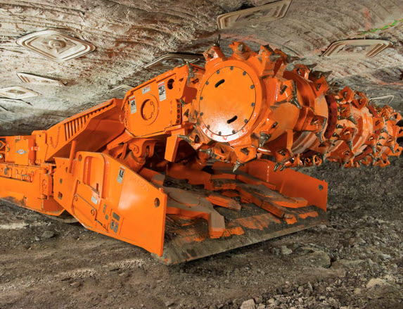
Let’s look at the next picture to understand what happens to the coal.
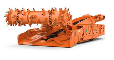
Here you can see it more clearly. The gathering arms pull the coal onto a chain conveyor, which runs the length of the machine. The chain conveyor consists of a metal trough and metal flight bars that are attached to a chain. The flight bars, which are painted black in this picture, are pulled along the metal “pan,” or trough, by the chain. In this manner, the mined material is conveyed to the rear of the machine. The rear of the machine is known as the tail or tailpiece, and it can swing over a limited arc. The tailpiece is positioned over a waiting shuttle car, and the mined coal is fed into the shuttle car. The continuous miner will continue advancing forward with the sump-shear cycles until there is a reason to stop the advance. In U.S. coal mines, the forward advance is limited by a few factors: the need to ventilate the face to maintain safe methane levels and the need to install roof bolts to prevent roof failure. Further, by law, no miners can work under unsupported roof, which will limit the amount of advance. Once the maximum advance has been achieved, the machine will be trammed back out of the cut and moved to a new face.
All right, let’s stop and catch our breath! What have we accomplished with this innovation known as the continuous miner? We’ve replaced drilling, kerf cutting, blasting, and loading with one machine, thereby reducing the number of pieces of equipment, the number of miners, and importantly, the delays. We’ve achieved a remarkable gain in both production and productivity. So much so that conventional mining of coal is no longer practiced in this country. Of course, when you make these improvements, you then expose the next “weakest link” in the system. Based on what we’ve talked about, you probably have an inkling of the weak links. Take a guess!
Many of you have probably zeroed in on the shuttle car -- when the shuttle car is filled it trams to the section dump point and another shuttle car maneuvers into position. In the time that it takes for the full car to leave, and the waiting car to maneuver into position, the continuous miner is idled. That’s a delay that is going to adversely impact our “numbers”, i.e., production and productivity. We’re going to talk more about these haulage bottlenecks shortly, but as it turns out, this is a tough one to fix. There is another weak link, which some of you have undoubtedly spotted: the need to limit the continuous miner’s advance so that the roof can be bolted and ventilation can be extended.
Allow me to introduce you to the Miner-Bolter. It took a number of years to work out the kinks, but today these machines work well. There are different configurations, but the principle is the same: incorporate the bolter into the miner. A bolter operator stands on the platform immediately behind the bolter carriage on both sides of the machine. While the cutting drum is cutting coal, the bolter operators are drilling holes and installing bolts. There is a linked platform to allow the bolters to remain stationary while the cutting head is advancing forward.
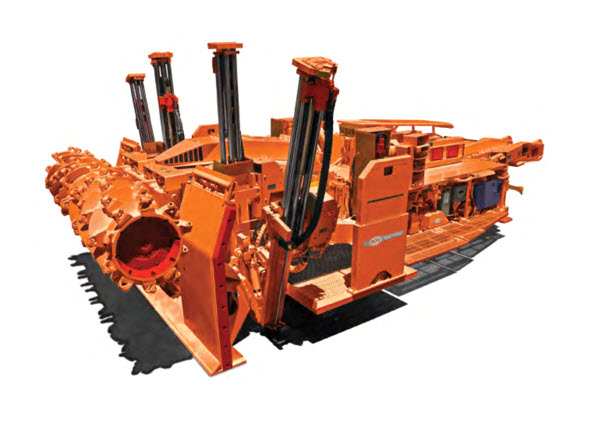
Hydraulic canopies are essential to protect the bolter operators while they are drilling and bolting. The canopies are not extended in this picture, but in the next photo they are, giving you a clearer view.
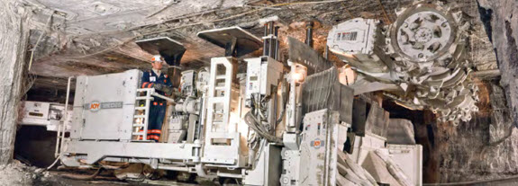
Typically, there will be a ventilation tube, on the order of 24” in diameter, hung near the roof against the side rib. This tubing will be extended as the continuous miner advances forward, providing the air needed to sweep the face and remove dust and gas.
Although remarkable gains have been achieved, there remains the weak link with the shuttle cars. In fact, there are a couple of options that can be considered. Before taking up this topic, however, I want to say a few more things about these continuous miners.
5.3.2: Continuous Miners for Noncoal Applications
5.3.2: Continuous Miners for Noncoal Applications
The impetus for developing the continuous miner came from the coal mines, but their application has grown beyond coal. The motivation for using them in noncoal mines is the same: eliminate delays wherever possible. In the case of the metal/nonmetal mines, the desire is to eliminate the discrete unit operations of drilling, blasting, and loading, along with the attendant delays. Unfortunately, there is a practical limitation that cannot be overcome in many cases. It is the hardness of the ore. The carbide cutting bits must be able to penetrate and fracture the ore, and do so with some speed and without destroying the bits in a short period of time. The limit is currently a compressive strength of around 80 MPa. This means, for example, that coal, salt, trona, potash, and some copper deposits are suitable, whereas most limestone and lead/zinc deposits are not. Pushing that limit ever higher is the goal of researchers, manufacturers, and the mining companies.
The structure and appearance of the continuous miner will change somewhat for those machines designed for use in harder rock deposits. The miner shown in the picture below looks similar to the one designed for operation in a coal mine, but there are a few subtle and important differences. The size of the machine reflects the thicker deposit in which this machine will be used, the structure is reinforced, and the lacing pattern of the bits is different – larger but fewer bits to concentrate the available energy to achieve fragmentation of the harder rock.
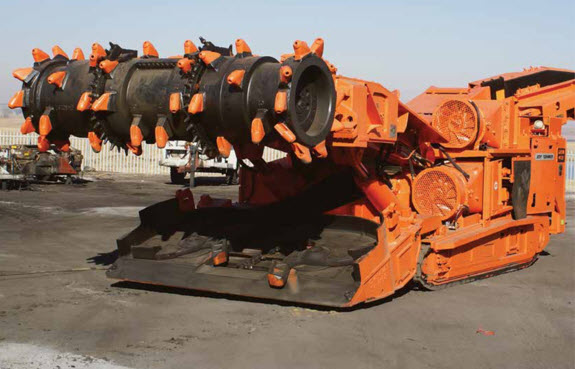
As the hardness of the rock increases, the cutting head will become much smaller, but for the same reason – concentrate more energy into a small area of the rock. Look at what’s happened to the size of the cutting head on this machine. The arm, on which the cutting head is mounted, has the ability to swing and extend. Note the bit marks in the top of the deposit. This configuration of continuous miner is often known as a roadheader, which is based on its European heritage and its use in driving gateroads. Also, take note of the size of the gathering pan and the two gathering arms.
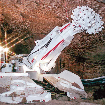
With this overview of continuous miners behind us, we can now return to this question of the shuttle car, and what to do about the inherent delay. Well, it turns out that this is really part of a larger and age-old problem: batch versus continuous haulage.
5.3.3: Batch versus Continuous Haulage
5.3.3: Batch versus Continuous Haulage
Batch haulage is the term given to the discrete movement of material. Shuttle cars, rail cars, hoist skips, and trucks are common examples of batch haulage. Conveyors and hydraulic slurry are two examples of continuous haulage. Over the years, the goal has been and continues to be, the replacement of batch with continuous haulage. And, we’ve been reasonably successful in many cases.
Rail haulage has been replaced with belt conveyors in many mines. Moving trains around the mine, ensuring a supply of empty cars where they are needed while moving loaded cars out of the mine and doing so over limited track networks has been a daunting challenge. Gone are the days when rail haulage was used in open-pit mines and most coal mines. However, there are still applications where it is the haulage of choice. If you have to move enormous volumes over a great distance, it is a viable choice. Probably, you will find the greatest use of rail in very deep underground metal mines.
Skip haulage or hoists have been replaced in many mines by driving slopes and using rail or belt haulage, with the latter being more prevalent today. In shallower underground mines, vertical belts are being used to replace hoisting up shafts. Still, in many mines, there is no reasonable alternative to a hoist. Deep mines, thousands of feet below the surface, rely solely on skips to remove the ore. Mines at which there is no ability to put in a slope, and which are a bit too deep for vertical belts, will continue to utilize hoists.
Truck haulage continues to be prevalent in surface mining because they can transport huge volumes of material economically from the working face to the processing plant. Truck haulage is also common in underground hardrock mines that have a slope or ramp to the surface so that the material can be transported from the working face to the plant. Oversize material is generally not a problem for trucks, but is a big problem for conveyors. Abrasive rocks are not a problem for trucks, but are for conveyors.
In certain open pit mines, which are very deep, the time required for a haul truck to make its way out of the pit can become excessive. In these cases, high angle conveyors can be used to good advantage.
The haulage examples that I’ve described so far can be categorized as outby haulage, i.e., the part of the materials handling system used to transport the material through the mine and to the plant. This distinction may seem odd. In the case of truck haulage, as we just discussed, the truck is loaded at the face and then travels to the plant. However, there are many examples, particularly in underground mines, where there is an intermediate form of materials handling. In these instances, the ore at the face is loaded onto one form of materials handling, transported a short distance, and then transferred to the outby haulage system for the trip out of the mine and to the plant.
It is in the form of intermediate haulage that we encounter our old friend, the shuttle car. The LHD would be another example. And this brings us back to that question: what can we do about that weak link, the shuttle car?
The area around the active working faces is very dynamic. It is difficult to construct semi-permanent infrastructure in this area; and it is for this reason that intermediate haulage has evolved. If we are to make an improvement, we would need a conveyor belt that was mobile, i.e., it could travel around the working faces, following the continuous miners or loaders. Prototypes of such systems have been built for use in underground metal mines to replace LHDs, but they have met with little success. In the case of soft rock applications, and notably coal and salt, there are commercially available technologies to meet the need, in specific circumstances. Here is a picture of a commercially available flexible conveyor. These units can turn corners and can be piggybacked to provide a continuous path of several hundred feet between the continuous miner and the section dump point. Recall that it is at the section dump point where the coal is fed onto the main or outby conveyor belt. This technology is being used successfully in some salt mines, but has found limited application in underground coal mines. For reasons that lie beyond the scope of this discussion, they work best in shallow mines with small pillars; and that is a small subset of all underground coal mines.
But not to despair, there is one other option in limited but successful use.
Rather than having the continuous miner load into a shuttle car, and being captive to the availability of shuttle cars, what if we allowed the continuous miner to dump onto the mine floor? Sounds crazy, right? But, not really. We could use a loading machine to clear away the pile, and trust me, loading machines can load a shuttle car very quickly. So, the shuttle cars would queue up for loading, but if there were a delay, the continuous miner would be able to continue mining without incurring a delay. Sure, the pile behind the machine might grow rather large, but no worries. The loading machine will get rid of it quickly. As you can see in the picture, the loading machine has a larger set of gathering arms than the continuous miner. The operating principle is the same, however: the gathering arms pull the coal into the belly of the machine and onto the chain conveyor.
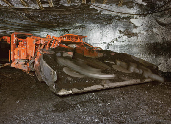
And now, having addressed the quest for continuous, we not only understand the technology options, but we’ve become more familiar with the key concepts of availability, system delays, and batch versus continuous haulage.
There is one final unit operation to study, and one that is a huge part of most mining methods. It’s generally one of the more popular topics among mining students as well: explosives and blasting!
Lesson 5.4: Drilling
Lesson 5.4: Drilling
We looked briefly at drills in Lesson 5.1, as part of an overall survey of the unit operations for winning the ore. I showed you some pictures of different types of drills, and we talked about a few drilling applications. Here in this short lesson, I want to approach the topic of drilling more systematically.
Drilling is done for many reasons, and examples include:
- Create a cavity that can be filled with explosives, as part of a blast round.
- Create a hole to install a rock or cable bolt.
- Degas a coal seam, i.e., drain the methane, prior to mining by drilling holes from which the gas can be removed.
- Drill boreholes for solution mining.
- Drill water wells to provide water for the mine, or to monitor groundwater conditions.
- Obtain either cores or cuttings for exploration purposes.
This is a fairly complete list. While the drilling equipment may look differently depending on the application, the principles are similar. Here, we want to focus on the common principles.
Regardless of our reason for drilling, the goal is to penetrate the rock. We are going to focus on mechanical penetration, although there are a tiny number of applications for water jet and thermal penetration. Penetration occurs when we cause a local failure of the rock and remove the failed pieces, known as cuttings, from the hole. Simplistically, the rock fails in compression or tension. Drill bits create one or both of these forces, which causes the rock to fail. Often a given bit design will create predominately one type of force and the other to a lesser extent.
Percussive energy causes failure of the rock in compression. Imagine taking a sharp chisel, placing the edge on a rock, and striking it with a hammer. As you strike the chisel, it is pressed into the rock, and puts the rock underneath the chisel edge in compression. There is some crushing under the chisel edge, but importantly, cracks will propagate outward, and chips of rock will be released. We could strike the chisel with our hammer again, and similar effect will follow, although perhaps not giving us the same degree of fracturing. We could strike a third blow, and while we would see our indentation or groove become slightly deeper, the penetration would be again less. If we want to achieve a better penetration rate, we need to index our chisel bit; i.e., after each strike, we need to rotate the chisel edge by say 15°. This results in dramatically improved penetration. Thus, percussion drills index the bit after each strike. A percussion drill may strike more than once per second, and will index the bit after each strike.
Rotary energy causes failure of rock in tension and shear. Imagine taking our chisel, and while bearing down on the chisel, we also rotate it, dragging the chisel edge across the surface of the rock. In so doing, we will exceed the tensile and shear strength of the rock, and rock fragments will “peel” away. Of course, a mechanical drill will be able to rotate the drag bit much faster than you ever could! Rotation rates may exceed one per second. Intuitively, you probably suspect that rotary methods are only effective with softer materials, and you are correct. Rotary bits with diamond cutters, suitable for use in hard materials, are commercially available, but not normally used in mining applications.
If we wanted to make a broad statement, we could say that the lowest drilling costs are realized by using rotary drag bits in soft materials, rotary-percussion bits in medium hard to hard materials, and percussion bits in very hard materials.
The resistance of the rock to drilling is termed its drilling strength. This is an empirical term used to make comparisons, but it is not quantified in the way we can quantify engineering parameters such as compressive strength or strain, for example. Nonetheless, you will find tables giving the relative drilling strength of different materials, and these tables are informative.
One could spend an entire course on the theory of drilling and rock fragmentation, but for our purposes to utilize drills, there’s not much more that you need to know about the mechanics of rock penetration!
The piece of equipment that we refer to as a “drill” is a system of four components.
- The drill is the power source, which often referred to as the hammer, and the associated frame or carriage, that converts electrical, pneumatic, or hydraulic, internal-combustion energy into percussive and/or rotational energy. Typically, a diesel engine and/or electric motor power either an air compressor or a hydraulic pump, and the high-pressure air or hydraulic fluid directly power a motor to supply energy to the drill bit. In years past, large (huge) air compressor plants were installed on the surface or at main levels underground, and large air distribution networks were installed to provide compressed air to the drills. This would be a rarity today.
- The drill rod, a.k.a. steel, stem, or pipe, transmits the energy from the drill to the drill bit. Remember that this component is not used to transfer power in the case of the down-the-hole drill. This style drill incorporates both the power converter and the bit. Hydraulic fluid or compressed air is provided directly to the down-the-hole drill, which converts the supplied energy to rotary and percussive energy for the drill bit.
- The drill bit is designed to fragment the rock when energy is applied to it.
- Circulation fluid, a.k.a. drilling fluid, flushes the cuttings from the bottom of the hole and cools the bit. If the cuttings are not removed immediately from the hole, they will pack in the bottom and quickly arrest any penetration. Compressed air is often used to remove the cuttings and to provide a modest amount of cooling to the bit. In other cases, water may be used, or occasionally in mining applications, clays and other materials will be mixed with the water to provide improve cooling of the bit and to remove the cuttings from deep holes.
Drill types may be classified by:
- Hammer location
- top hammer
- down-the-hole
- Drilling action
- rotary
- percussion
- rotary-percussion
- Mount or Carriage
- track
- platform
- truck
- Power Source
- diesel engine powering an air compressor, often called “diesel over air”
- electric motor powering a hydraulic pump, often called “electric over hydraulic”
When you are out and about the industry, you will hear people say they have a two-boom jumbo that’s electric over hydraulic, or we’re using an air-track drill in our quarry. These colloquial names are built on this list.
We looked at some pictures of drills in Lesson 5.1. Here I want to show you a few photos of bits.
Here is a cross section of a down-the-hole bit.
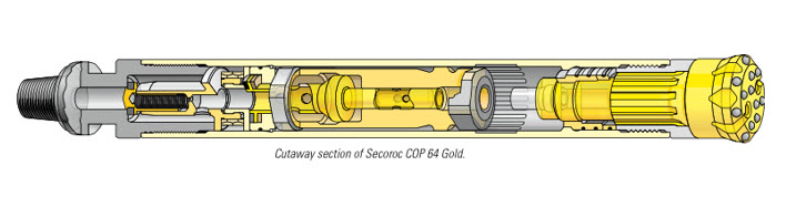
And give it a sense of scale, here is the same bit in the hands of a driller.
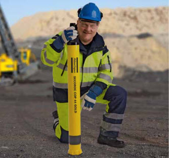
On the left, we have small 2” percussive bit. On the right side, we have a small rotary drag bit.
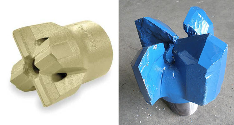
Here is the real workhorse of the drilling industry – the roller tricone bit. Downward force, i.e., thrust, is applied to this bit as well as rotation. As the bit rotates, the individual roller cones are caused to rotate, and then each bit tooth successively impacts the bottom of the hole. These are very effective bits. The size of the teeth on the roller cones will depend on the hardness of the rock. In softer materials, the teeth will be large and wedge shaped. Bits for harder materials will become smaller, and for the hardest materials, the teeth are small buttons or beads. Why do you think the size of the teeth would change?
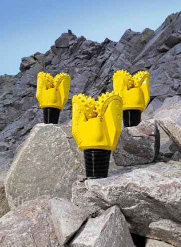
The drilling strength of the rock, i.e., its resistance to penetration, will have a significant effect on the cost of drilling. It is not the only parameter to do so, however. Other factors that will affect drilling performance can be organized into four groups:
Operating Factors
These affect the four components of the drilling system (drill, rod, bit, and fluid).
They are largely controllable and include factors that affect the tools (drill power, blow energy and frequency, rotary speed, thrust, and rod design) and drillhole cleaning (fluid properties and flow rate).
Drillhole Factors
These include hole size, length, and inclination; they are dictated by outside requirements and thus are largely uncontrollable. Hole diameters in surface mining are typically 6 to 18 in. (150 to 450 mm); underground, they typically range from 1.5 to 7 in. (40 to 175 mm).
Rock Factors
These consist of properties of the rock, geological conditions surrounding the rock, and the state of stress acting on the drillhole. Often referred to as drillability factors, they determine the strength of the rock and limit drill performance. Because these factors are a result of the geologic environment, they are largely uncontrollable. Make a note of the importance of the Blast Hole log! We’ll discuss that further when we talking about explosives and blasting.
Service Factors
These variables include labor and supervision, power supply, job site conditions, weather, and so forth. Except for labor and supervision, they are independent factors and cannot often be affected by the drill operator.
The performance metrics for drilling are:
- cost/ft of hole drilled; and
- drilling cost/ ton of material produced
- feet-drilled/ ton of material produced (known as the drillability factor)
You will find all three of these in common use.
Never forget that we strive to optimize the system, not just the subsystems. This it is not just about the drilling cost, but also the associated blasting cost, since we are drilling specifically to conduct blasting. So, a goal is to achieve a low drilling and blasting cost.
I will mention it now for completeness, and we’ll discuss it in the next set of lessons: the typical performance metrics for blasting are:
- cost/ton
- lb-explosive / ton of blasted material or lb-explosive/ ft3 in-place (bank) material blasted (both of these are known as powder factor)
Drillability factor and powder factor are two very important metrics for use to keep track of, in our operations.
Before leaving the performance metrics specifically, and drilling in general, I need to add that it is not just about optimizing drilling and blasting, but what else? Well, loading in particular, and then materials handling, and of course mineral processing. Actions or inactions within any of these can adversely affect the profitability for the mining operation, and our decisions at each step must be informed by a knowledge of the impact of those actions on subsequent operations. This will become clearer as you acquire more and more knowledge throughout this course.
Module 6: Explosives and Blasting
Module 6 Overview
Module 6 Overview
We looked at unit operations in the last module, and learned that in a conventional cycle we have a drill-blast-load-haul sequence of operations; but we did not discuss the unit operation of blasting. We’ll do that in this module.
We use millions of pounds of explosives every week in mining to loosen overburden so that it is easier to dig, to break rock so that it can be freed from the rock face and loaded, and to create openings in underground mines, among dozens of other uses. Moreover, we do this with no injuries or fatalities and a minimum number of complaints from the mines’ neighbors. It is not an accident that we have achieved these positive outcomes; rather, it is good engineering.
In this module we’ll learn: about the blasting agents commonly used in the mining industry; how to design a blast round; how to initiate a blast; and how to avoid poor blasting outcomes.
Learning Outcomes
At the successful completion of this module, you should be able to:
- demonstrate knowledge of the basic properties of explosives, including oxygen balance, the basic concepts of fragmentation, the blasting agents, and the initiation technologies commonly used in mining;
- demonstrate knowledge of the design parameters for a blast:
- burden, spacing, and free face,
- hole diameter, length, stemming, decking,
- powder factor,
- fragmentation and throw,
- ground vibration and air blast;
- demonstrate knowledge of typical blasting practices for:
- bench blasting rounds for surface and underground mines,
- stoping or drifting rounds;
- calculate:
- powder factor for a given blast round,
- burden, spacing, and stemming distance given a blast hole diameter or given a typical powder factor,
- maximum charge weight/delay, given a vibration limit;
- demonstrate a knowledge of the factors that can adversely affect the outcome of a blast, or the relationship of poor engineering, drilling or explosives blending/loading practices on the outcome of the blast;
- identify potential safety and health issues, and proactive measures to prevent adverse outcomes, related to the following:
- storage and handling,
- flyrock,
- fume and dust exposure,
- air blast and vibration.
Lesson 6.1: The Big Bang
Lesson 6.1: The Big Bang
The mining industry is a major consumer of explosives, and the ore winning process is heavily dependent on blasting. The purchase and use of explosives is a significant cost, but a potentially greater cost is the effect of the blast on the overall cost of the product. An improperly designed or executed blast can increase loading time and cost, create future ground control problems, i.e., delays and costs, increase crushing costs, cause excessive fines that may be unsalable, and so on. Paying close attention to the results of each blast, and taking appropriate corrective action, can yield immediate benefits. Of course, you have to know what to look for, and how to achieve a desired result. So, let’s start at the beginning, and answer two fundamental questions! Why do we blast, and how do we blast?
6.1.1: Why do We Blast?
6.1.1: Why do We Blast?
Yes, we blast to break the rock, but we have specific goals beyond simply achieving fragmentation of the rock! The desired outcome of a blast is broken material:
- fragmented to a specified size distribution,
- thrown a certain distance, and
- distributed in a pile that is placed to facilitate loading.
The size distribution is important for several reasons, and these reasons vary with different commodities.
Generally, the blasted material must be handled in some fashion, e.g., to load it into a haul truck or to cast it onto a spoil pile. The size of the blasted material must be consistent with the capabilities of the equipment that will be used to move it.
Oversize rock, i.e., rock that is larger than can be handled, can’t be loaded or if it can be loaded, it is too large to fit into the crusher. This creates multiple problems. It introduces delays in production, it is time-consuming, costly, and sometimes dangerous to practice what is known as secondary breakage.
The production of fines, i.e., very small particles, in the blast can be desirable in certain cases where an ore is to be beneficiated. In other cases, excess production of fines is undesirable. In the crushed stone market, for example, fines are excluded from many products, and it is expensive to re-handle and dispose of an unsaleable product.
The throw distance and the pile placement are closely related.
Pile placement
Pile placement is the distribution of the blasted material. Is the pile of blasted rock 30’ wide, 10’ long, and 10’ deep, or is 30’ wide, 80’ long, and 15” deep, or somewhere in between? There will be an optimum depth for loading. If the pile is too deep, the loader will waste time digging to load the bucket. If the pile is too dispersed, time will be wasted maneuvering over a large area to load the material.
Throw distance
This is how far the blasted material is moved. There are examples in surface mining where the blast is used to move material to a previously mined strip, rather than using a dragline or shovel. This is known as cast blasting, and obviously the distance that the blasted material is moved is a critical performance parameter. Throw is also important to ensure that the blasted material can be loaded or dug. Without adequate throw, the fragmented material will sit back down, and be extremely difficult to access. This can be a problem when advancing a face in an underground mine and, accordingly, we design the blasting pattern to ensure that the fragmented rock is lifted and thrown away from the virgin rock.
6.1.2: How do We Blast?
6.1.2: How do We Blast?
Very carefully! Actually, I am serious!!! There’s a difference between civil and military blasting. In the latter, their goal is usually to “blow things up.” In civil projects, such as mining, our goals are to use as little explosive as possible, as safely as possible, and to have no collateral damage, while achieving the design outcome for the blast. This is not easily accomplished and requires both good engineering and faithful implementation of the blast design by the drillers and blasters. The short answer to the question of “how do we blast” is as follows.
- We create a cavity, typically a drilled hole, to accept an explosive. The diameter of the hole will depend on the amount of explosive energy that we want in the hole.
- We will drill multiple holes, and the distances among the holes will be an engineered parameter.
- We fill the cavity, partially, with a blasting agent, i.e., an explosive. The type and formulation of explosives is an engineering decision.
- We place initiators, primers, and sometimes boosters in the hole with the blasting agent.
- The initiators trigger the process. They can be nonelectric or electric, and some are commonly known as blasting caps. These initiators may include a time delay, which allows us to design a specific sequence for the initiation of the blast.
- The primer is a small explosive charge that is set off by the initiator, and which has sufficient energy to set off the blasting agent. Explosives commonly used today are not cap-sensitive, meaning that the initiators do not have enough energy to set off the blasting agent. For this reason, we need to insert the initiator into the primer before dropping it into the hole.
- Boosters are used to ensure that the explosion propagates through the entire column of explosive. This is a concern in longer holes and holes of smaller diameter.
- We connect the initiators in each hole together using nonelectric tube/cord or electric wires, and these terminate at the point where the blast will be fired, i.e., the blaster will “push the plunger” or “throw the switch.”
The placement of the holes and the timing sequence of when the holes are “fired” constitute the blasting pattern.
Collateral Damage
I said that one of the goals of blasting is to avoid collateral damage, which we do through proper design and execution of the blast. But, what do we mean by collateral damage? Here are the primary ones that we constantly have to assess.
Overbreak
This is when fractures from the blast propagate beyond the intended region. Imagine that you want to drill and blast a tunnel opening through a mountain, and you are designing for an opening that is 30’ wide and 15’ high. However, due to improper design or execution, cracks have propagated to 18’ high. Over time, it is likely that pieces of rock will begin to fall out of the tunnel roof, creating a safety hazard as well as delays in using the tunnel.
Flyrock
Flyrock is a large chunk of rock that is propelled well beyond the throw region for the blast. These chunks can weigh hundreds of pounds or even more than a ton, and travel distances of several hundred feet. Over the years, flyrock has caused numerous fatalities and millions of dollars of property and equipment damage. Proper design and execution are necessary to prevent flyrock.
Gas production
Gas production is an intended action during a blast, but the production of excess quantities of toxic gases, notably CO and NOx, is to be avoided. Improper on-site formulation of the blasting agent and problems with loading are often responsible for this problem. It should be noted that this is a hazard in both surface and underground mines.
Ground vibration
Like gas production, ground vibration is an intended consequence of blasting. However, excessive ground vibration can damage structures, and the level of vibration at the boundary of the mine’s property is regulated. Careful design of the blasting pattern, and especially the timing of the holes, is required to keep the ground vibration within prescribed limits.
Air blast
This occurs when excess energy from the blast creates a shock wave in the air. Certain weather conditions will cause the air blast to be bounced back to the surface but at some distance from the blast. There is little danger of personal or structural damage from an air blast, but it can precipitate a barrage of angry complaints from people who live in proximity to a surface mine. Nothing good ever comes from irritating the locals! Air blast can be reduced through proper design the blasting pattern and the choice of detonators used to link the holes together.
Misfires
These are not really “collateral damage” per se, but they are an unintended consequence. A misfire occurs when some of the blasting agent in a hole, or multiple holes, remain undetonated after the blast. This explosive could go off at a later time, such as during loading, and cause serious personal injury or death. Misfires can be avoided through careful attention to the execution, as well as the design, of the blast.
Good Engineering and Execution
Throughout this discussion, I have emphasized the proper design and execution of the blast. By execution, I mean the drilling and loading of the holes. Poor drilling or loading procedures will compromise the best design, and similarly, proper drilling and loading cannot compensate for a poorly engineered blast round.
It starts with good engineering, and specifically:
Design of the blasting round is concerned with:
- the choice of the blasting agent;
- the choice of detonators, primers, and boosters;
- the use of free faces. A free face is an unconfined surface, through which the blasted material is free to move unimpeded;
- the distance between holes, known as the spacing, and the distance between a hole the nearest free face, known as the burden;
- the number of holes;
- the diameter of the hole;
- the depth or length of the hole;
- the use of decking, when needed, and stemming. Decking is an inert material used at certain locations within the column of explosive when it would be undesirable to have explosive at that part of the drill hole. Stemming is an inert material placed in the top or front of the hole. It is necessary to help provide proper confinement for the blast, ensure safety, and reduce airblast;
- the timing of when each hole is detonated;
- the overall positioning or arrangement of the holes, including the use of unloaded holes;
and ends with good execution by the drillers and the blasters. Specifically for the driller:
- accurate positioning of the collar, i.e., drilling the hole exactly at the specified location;
- control the drilling angle, i.e., drilling the hole at exactly the specified angle;
- control the depth or length of the hole;
- accurate logging of the holes during drilling (applicable primarily to surface mining applications);
specifically for the blaster:
- correct mixing of the blasting agent at the hole (if batch loaded);
- proper loading procedures if there is water in the hole;
- correct loading rate;
- correct placement of decking, boosters, and primers;
- proper placement of stemming and stemming to the design depth.
6.1.3: Dance of the Detonators
6.1.3: Dance of the Detonators
I want to conclude this introduction to explosives and blasting with a short video clip (4:04) showing multiple controlled explosions. There is no narration for the video, but the blasts are accompanied with a musical soundtrack.
Look for the following:
- The relative timing of the holes, as indicated by when they detonate.
- The initiation of the blast in the holes prior to the detonation of the explosive, as indicated by the flashes of light moving from hole-to-hole, as well as the small dust clouds at the collar of each hole.
- The movement of the blasted material at the free faces (not always apparent).
- The couple of blasts that are done underwater.
Direct link to video [51] if not showing below
I hope that you enjoyed this video. It is entertaining! It also represents good blasting practice, which you will come to better understand as you learn more about explosives and blasting practice.
Lesson 6.2: Explosives
Lesson 6.2: Explosives
We took a “bird's-eye view” of explosives and blasting in the last lesson. Now, we need to zoom in and look at many of these concepts in greater detail and with more rigor. First, a definition:
An explosive is an agent, compound, or mixture that undergoes very rapid decomposition when initiated by heat, impact, friction, or shock.
- This decomposition is a high-velocity, exothermic reaction, accompanied by the liberation of vast amounts of energy and hot gases at tremendously high pressure.
- High explosives produce shock, which fragments rock, and force, in the form of expanding gases, which displace and throw the rock.
The detonation velocity (DV) is the speed at which the detonation front propagates through a column of explosive.
- The explosive is said to detonate if the DV is supersonic, DV>3000fpm
- The explosive is said to deflagrate if the DV is subsonic, DV<3000fpm
In everyday conversation, some use the word detonate to mean either detonation or deflagration. From this point forward, we should be more precise in our use of the words.
The Three Common Components of Industrial Explosives:
Oxidizers
This group contributes oxygen, and includes nitrated salts such as ammonium, calcium, and sodium nitrate.
Fuels
Fuels produce heat, and include fuel oil, carbon, granular aluminum, TNT, black powder, and other carbonaceous material. Some of these materials are referred to as sensitizers, which increase the energy output, e.g., granular aluminum. We are not going to talk about the use of black powder because it is illegal for use in underground coal mines, and that was its only application to mining. TNT or dynamite is rarely used in mining applications due to the challenges of using it safely. Virtually all explosives used in the mining industry are based on ammonium nitrate and fuel oil (ANFO), and we will confine our discussion to those ANFO-based formulations.
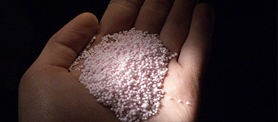
Stabilizers
These impart properties to improve the handling of the explosive and include flame retardants, gelatins, densifiers, emulsifying agents, and thickeners.
6.2.1: Mixing ANFO and the Oxygen Balance
6.2.1: Mixing ANFO and the Oxygen Balance
The proportion of oxidizers and fuels in the mix is critical to the performance of the explosive, and we say that the explosive must be oxygen balanced.
Oxygen Balance
It is important to achieve an oxygen balance within the explosive. This means there is exactly enough oxygen present to completely oxidize the contained fuel, but none left over to react with the contained nitrogen. We can calculate the proportion of ammonium nitrate and fuel oil to achieve an oxygen-balanced reaction. The decomposition of an oxygen-balanced ANFO is:
We can find the atomic weights for each of the elements from the periodic table.:
N = 14.006
H = 1.0078
N = 14.006
C = 12.009
And then, we can calculate the molecular weight of the ammonium nitrate and the fuel oil.
: molecular weight = 80.05 g/mol
: molecular weight = 14.03 g/mol
The ideal mixture, i.e., the oxygen-balanced mixture, consists of 3 moles of ammonium nitrate and one mole of fuel oil.
Next, we should find the weight ratio of ammonium nitrate to fuel oil.
For 3 moles of : 3*80.05 = 240.15 g
For 1 mole of : 1*14.03 = 14.03 g
The molecular weight of ANFO is, therefore: 240.15 + 14.03 = 254.18 g
The percent by weight is:
: (240.15 / 254.18) *100 = 94.5% by weight
: (14.03 / 254.18) * 100 = 5.5% by weight
So, now we know that when we mix the ammonium nitrate with the fuel oil, we need to do it in this proportion if we want an oxygen balanced reaction.
We can calculate the density of ANFO mixed to this ratio. Why we would we want to do that? If we know the weight per unit volume of the correct mix, then we can tell the blasters who make the mixture in the field to weigh one cup of the mixture to ensure the weight matches the specification weight. Note, I used “cup” as the volume measurement where one cup equals eight fluid ounces. You can use any unit, as long as you are consistent.
Let’s look at an example.
We will assume that the industrial-grade ammonium nitrate and fuel oil have the following densities: 53 lb/ft3 for the ammonium nitrate and 8.0 lb/gal for the fuel oil. How much ammonium nitrate will be required for each gallon of fuel oil to make an oxygen-balanced batch of ANFO? We will need to mix 2.6 ft3 of ammonium nitrate with that gallon of fuel oil. You should verify this result.
Continuing with this example: we know that the blasters will have a scale on the mixing truck and they will have a “cup”, which they will use to do a “cup density” check. In other words, they will fill the cup with their batch of mixed ANFO and weigh it. They will compare that weight to the weight that they have been given as the specified weight. If the blaster is using an 8-ounce container for the cup density check, what weight should be displayed on the scale?
You don’t have sufficient information to answer this question. What is the calculation that you need to do to answer the question, and what are you missing?
Although you know the weight of each ingredient in the mix, you don’t know the density of the mix. The manufacturer of the ammonium nitrate would be able to give you that information, or you could do a simple experiment in the lab to determine the density of that mix. For our purposes here, let’s assume that the density of this mix is 6.68 lb/gal. Therefore, the number that you need to give to your blaster is 0.42 lb.
The mixing equipment on the truck requires regular calibration, and even if calibrated, sometimes it can malfunction. Thus, it is recommended that blasters perform a cup-density check frequently, e.g., every 5 or so holes in a surface mine application.
We’ve looked at the ideal, i.e., oxygen-balanced mixture. Let’s look at two other cases in which we have too little or too much ammonium nitrate for the amount of fuel oil that has been added. We’ll choose a 92: 8 ratio for the first case and a 96.6: 3.4 ratio for the second case I’ve picked these ratios so that we have an integer number of moles in our formula.
Thus, for the first case with a 92:8 ratio, we have:
And for the second case, with a 96.6 : 3.4 ratio, we have:
Let’s look at the right-hand side of the equations. In the case of ideal mix, the products of the reaction, in addition to the energy that is not shown, are water vapor, carbon dioxide and nitrogen. In the first case of too little oxidizer, i.e., the ammonium nitrate, we produce carbon monoxide, a deadly gas. In the second case of too much oxidizer, we produce NO. The gas, NO, changes to NO2 when exposed to the atmosphere. NO2 is a toxic, but unlike CO, which is colorless, NO2 produces a bright yellow-orange cloud.
We are not going to calculate the volume of toxic gas produced, but be aware that it is significant. In addition to the production of toxic gas, the energy release is reduced.
The oxygen balance can be lost for varied reasons. The most common include:
- poor quality control at the batch mixing truck;
- incorrect formulation, for example by adding a sensitizer like aluminum, but not accounting for it in the addition of the fuel oil;
- water in the hole;
- lack of confinement;
- improper stemming;
- improper timing of adjacent holes, allowing the explosive to become unconfined by the time it detonates;
- open-air blasting;
- explosives at the collar of the hole (increases fume production, not fragmentation).
6.2.2: Fumes
6.2.2: Fumes
The whole point of ensuring an oxygen balance is to achieve the maximum energy from the reaction and to prevent the generation of toxic gases. Remember, however, that the production of large quantities of gas is key to the efficacy of the explosive to fragment rock. On average 700 - 1000 l of gases/kg of explosive are produced, and these are mostly benign – N, CO2, and water. It is impractical to achieve a perfect mix in the field, shot after shot, and consequently, a small (<4%) toxic component of about 3% CO and 1% NO2, depending on the oxygen balance, is not unusual. The percentage of toxic gases will increase significantly as the oxygen balance deteriorates.
Due to the possibility of a toxic component in a well-designed blast, certain precautions must be taken. The ventilation system in underground mines must be designed to dilute and carry away the gases from the blast, and no one should be allowed back into that part of the mine until sufficient time has passed to eliminate any gases from the blast. Some mines, and particularly smaller ones, make it a practice of blasting after the crew from the last shift of the day has exited the mine and the next shift won’t return until the following day. Other mines don’t have that luxury, and must ensure that a properly designed ventilation system is in place.
Fumes are normally less of a concern in a surface mine. However, it is important to note that fumes can be trapped in a pile of blasted rock only to be liberated when the pile is loaded out. There have been a few fatalities from this, so this possibility is not to be ignored. The precaution of watering down the pile prior to loading is practiced both underground and in some surface applications. In addition to addressing a potential fume issue, the wetting action suppresses respirable dust.
A significant hazard can develop at surface mines if there is an excess production of NO2 or CO. In the late 1990s, I was part of a team investigating a problem in the Powder River Basin, in which the large blasts were producing thick yellow clouds of NOx – clouds that covered acres, and would drift for miles before dispersing! Fortunately, there were no reported ill effects and no fatalities, and that was lucky. My agency became involved when such clouds from a mine settled in a nearby town, near an elementary school filled with children. In the Basin, the problem was found to be water in the hole primarily, and loss of confinement as a secondary cause.
There was another illustrative problem that we investigated involving CO. These were trench-blasting applications, and there were a few fatalities due to CO poisoning. CO from the blast was trapped in the ground, but over a day or so, the gas migrated along a pipeline and entered a structure (basement), creating a toxic environment in the basement.
Fumes are an expected consequence when explosives are used. Proper procedures can help ensure an oxygen-balanced explosion, but will not guarantee a blast completely free of toxic fumes. Precautions, such as those mentioned here, must be implemented.
6.2.3: Classification of Common Industrial Explosives
6.2.3: Classification of Common Industrial Explosives
The U.S. Bureau of Alcohol, Tobacco, and Firearms (ATF) regulates different aspects of explosives manufacture and use. They classify explosives according to the following definitions:
High Explosive (HE): an explosive material that can be caused to detonate with a No. 8 blasting cap when unconfined; and
Blasting Agent (BA): a mixture consisting of a fuel and oxidizer, intended for blasting but otherwise not an explosive (cannot be detonated with a No. 8 blasting cap).
HE’s that can be detonated directly with a No. 8 cap are called cap-sensitive.
BA’s that cannot be detonated directly with a No. 8 cap are called cap-insensitive or non-cap-sensitive.
Low Explosive (LE): an explosive material that can be caused to deflagrate (burn) when unconfined.
These definitions are important, as the terms and the underlying concepts are in everyday use. However, don’t worry about "what is a #8 blasting cap…" just know what it means to be cap sensitive or cap insensitive.
Examples of products in these classes are:
- High Explosives
- Dynamites
- Gelatins
- Semi-gelatins
- Water gels & slurries and Emulsions
- Blasting Agents
- Water gels & slurries and Emulsions
- ANFO
- Blends
- Low Explosives
- Black powder
Dynamites are rarely used industrially today because of safety concerns. For that matter, there is little use for the gelatins, semi-gelatins, and binaries per se in mining applications. Water gels, slurries, emulsions and ANFO blends are the predominate explosives in use. Note, however, that water gels, slurries, and emulsions can be formulated to be cap sensitive. This is why I have shown them under high explosives and blasting agents.
The use of black powder in underground coal mines was outlawed decades ago in this country because it will ignite coal dust and methane mixtures, making it an explosion hazard in these mines. Unfortunately, you will find it in use in the mines of some lesser-developed countries. The safe alternative to black powder is a permissible explosive, although there is little demand for low explosives in modern mining operations. We’ll talk a little more about this near the end of this lesson.
The blasting agents are often categorized as dry and wet blasting agents.
Dry Blasting Agents
The dry blasting agents are the ANFO blends, and are not cap sensitive. ANFO has the following characteristics:
- the ratio of industrial-grade AN to No. 2 fuel oil is 94.5 : 5.5 % by weight;
- aluminum particles can be added, up to 6 % , by weight, to increase the energy (heat) output;
- it is available in bulk (most common) or packaged;
- it has poor water resistance;
- the critical diameter is approximately 4";
- the specific gravity is over the range of 0.75 - 0.95;
- the detonation velocity is approximately 15,000 fps.
The industrial-grade AN is normally provided as prills, which are uniform beads of a few millimeters in diameter. We haven’t defined some of these characteristics, such as critical diameter, but will do so shortly.
The poor water resistance of the ANFO blends is a serious drawback because water is present more often than not. Sometimes, several feet of water will accumulate quickly in a vertical hole, and other times, a small amount of water will seep into the hole after loading. Regardless, this creates a significant problem. Wet blasting agents were developed to have better water resistance, and contain more than 5% water by weight. Another important characteristic of the wet-blasting agents is their higher density, which translates into being able to load more energy in the hole.
Wet Blasting Agents
There are two major types of wet blasting agents: water gels & slurries and emulsions. Water gels and slurries are technically different, but in common usage, the two terms are used interchangeably.
- Water gels consist of an inorganic oxidizer such as ammonium nitrate with a gelling agent along with additional suspended oxidizers, fuel, stabilizers, and so on. They are a colloidal suspension of solid AN particles suspended in a liquid AN solution that is gelled using cross-linking agents (think Jell-O), containing up to 20% water. The explosive becomes slurry with the addition of suspended solids and, in fact, slurries are more common. However, in everyday usage, the words are used interchangeably and we will do so here as well. Other key features of slurries include:
- they can be made cap sensitive, for example, adding up to 18% Al;
- they are available in bulk or packaged;
- they have good water resistance;
- the critical diameter is < 1";
- they have poor low-temperature performance;
- their specific gravity ranges from 1.15 - 1.45;
- the detonation velocity ranges from 14,500 fps - 18,500 fps.
- Emulsions consist of a two-liquid phase containing microscopic droplets of aqueous nitrates of salts (chiefly AN) dispersed in fuel oil, wax, or paraffin using an emulsifying agent (think Mayonnaise). Stabilizers, and so on are added to round out the mixture. Other key features of emulsions include:
- emulsions are more efficient than slurries;
- they are available in bulk or packaged;
- they have excellent water resistance;
- the critical diameter is < 1";
- they have poor low-temperature performance;
- their specific gravity ranges from 1.1 - 1.3;
- the detonation velocity ranges from 14,500 fps - 18,500 fps.
Blends are a mix of dry ANFO and emulsion, and this mix is often known as heavy ANFO. ANFO is inexpensive and emulsions are expensive. The blend is designed to capture the advantages of an emulsion, but at a lower cost. Specifically, the addition of the emulsion will improve the water resistance of straight ANFO, and it increases the density of the explosive, which means that more energy can be loaded into the hole. The ratio of ANFO is emulsion will range from 80:20 to 20:80. As the percentage of emulsion increases, the desirable characteristics of water resistance and density increase, but then, so does the cost. In practice, you would work with application engineers from the manufacturer to achieve the balance that best matched your unique needs. Other key features of blends include:
- emulsions are more efficient than slurries;
- they are available in bulk or packaged;
- they have improved water resistance;
- the critical diameter varies (<4” but greater than 1”);
- they have poor low temperature performance;
- their specific gravity ranges from 1.15 - 1.3;
- the detonation velocity ranges from 16,500 fps - 17,500 fps.
6.2.4: Permissible Explosives
6.2.4: Permissible Explosives
The term Permissible Explosive can be traced back to early in the 20th century when thousands of miners were being killed each year in the underground coal mines. Mine explosions caused many of those fatalities, and the mine explosions were set off by improper blasting practices. The U.S. Bureau of Mines conducted research to develop explosives that would not set off the mixtures of coal dust and methane that were typically found in the mines. Over the years, permissible came to mean two very important things: first, the explosive had been tested and certified by the USBM to meet the criteria; and second, the permissible explosive would be used according to a set of required practices. Without the latter, it is still possible to set off a mine explosion even though a certified-permissible explosive is used. Eventually, by the mid-20th century, mining laws mandated the use of permissible explosives and practices.
The migration from conventional to continuous mining practices in the coal mines has dramatically reduced the demand for permissible explosives in this country. Recently, around 900 metric tons of permissible explosives were sold in the U.S., whereas, in the mid-twentieth century, that number was closer to 60,000 metric tons! Nonetheless, it is commercially available and has application when it is necessary to blast in mines where methane could be present. Such applications would include: shooting the overlying strata for construction purposes in underground coal mines, e.g., for ventilation overcasts or increased headroom for belt drives/transfer points; and shooting large roof falls so that the rock can be loaded out and removed.
The permissible explosive must be used in accordance with the permissible practices. The key practices are as follows:
- qualified or certified persons, i.e., individuals meeting the requirements specified by the mining regulations, must conduct the blast.
- black powder, aluminum-cased detonators and safety fuses are prohibited;
- noncombustible stemming must be used;
- the minimum borehole spacing is 24” in coal and 18” in rock;
- no more than 20 boreholes are permitted to be fired in a round;
- no more than 3 lb of explosives can be loaded into the hole;
- the total delay period must be 1000 ms or less;
- the interval between delays must be at least 50 ms, but no more than 100 ms;
- the air must be tested for methane immediately before shots are fired, and the shot can be fired only if the concentration is less than 1.0 %;
- unconfined shooting is prohibited;
- all of the blasting circuits must be checked for continuity and resistance before the shot, using approved blasting galvanometer or blasting multi-meter.
6.2.5: Key Properties Affecting Choice of Explosives
6.2.5: Key Properties Affecting Choice of Explosives
There are many properties that define an explosive. Some are of most value to the engineers and scientists that formulate and test explosive products. Others are useful to mining engineers designing blast rounds. We’re going to focus on the latter, and such a list would include the following:
Properties of the explosive are key to the design of the blast round, and that will become clearer when we will talk about the design of blast rounds. However, properties of the rock are equally influential, and we’ll talk more about this in the future.
- Density: kg/m3.
- Weight strength: is a measure of the explosive energy, kcal/kg.
- Bulk strength: is the product of density and weight strength of the explosive; and is indicative of the explosive energy in the hole, kcal/m3.
- Critical diameter: the minimum diameter of the explosive column to sustain the detonation or deflagration. This will determine the size (diameter) of the hole that we drill.
- Critical density: the maximum density at which the explosion may not propagate. As holes become deeper, the concern is that the weight of the column will become so great that the density of the explosive near the bottom of the borehole will exceed the critical density.
- Sensitiveness: a measure of propagating ability. You will hear this term, but won’t use it in a calculation, although it may influence your decision to use boosters in the hole.
- Sensitivity: a measure of the energy required to initiate the explosive. For our purposes, we’re usually not interested in a quantitative measure of this property; but, rather, we need to know simply: is it or is it not cap-sensitive?
- Water resistance: a qualitative measure for our purposes.
Lesson 6.3: The Design of Blast Rounds
Lesson 6.3: The Design of Blast Rounds
We’re ready to design a blast… so, what do we need to do?
The design of a blast round generally means, at a minimum, to do the following.
- determine the size, i.e., the diameter, of the borehole, and the length of the hole;
- determine the geometric arrangement of the holes;
- determine the burden, spacing, and stemming;
- determine the delays for different holes, and the number of holes at each delay period.
Some elements of the design are common or applicable to the design of all types of blasting, while others are specific to a given type. We’ll cover the common elements in this course, and look at two types in more detail. As with many aspects of mining-engineering design, the design of blasts tends to be as much art as science. Make no mistake, however: the “art-of-practice” is informed by the science! And one goal here is to help you become proficient in applying the science.
The two types that we will focus on are bench blasting and drifting, and, together, these two account for the vast majority of all blasting done in mining. Bench blasting is used in most surface and underground mining methods, and drifting is used in the underground methods that utilize a drill and blast cycle.
Other important, but less common types that will not be examined in more detail here are:
- ring drilling & blasting: specific applications in certain underground M/NM mines, e.g., bell and draw point development in caving methods, and sublevel stoping;
- longhole drilling & blasting: specific applications in certain underground mining methods, e.g., sublevel stoping and shrinkage stoping;
- crater blasting: used in the vertical Crater Retreat (VCR) mining method;
- cast blasting: adaptation of bench blasting used in certain area surface applications, predominantly in the Powder River Basin surface coal mines.
In past lessons, we’ve defined some key terms for the design of a blast round. By way of review, these included the following:
- Free Face is an unconfined surface through which the broken material can move.
- Burden is the distance between the hole and the nearest free face.
- Spacing is the distance between holes.
- Stemming is the inert material used to confine the shot at the collar of the hole.
- Decking is unloaded space in the hole. Inert material is used as spacers for the unloaded space.
- Sub-drill is the added length of the borehole past the advance plane (horizontal) or the desired grade (vertical). In other words, if you wanted to blast a bench that was 50’ high, you might drill a that was 55’ deep. Why would you drill 5’ past the level that you wanted the bench? By doing so, i.e., sub-drilling, you will ensure a more even surface at 50’, which will make it easier to move equipment about the bench.
You will recall that we defined bulk strength, BS, as the product of the density and the weight strength of the explosive. While the weight strength tells us how much energy the explosive will release per unit weight, bulk strength is a more informative metric. The bulk strength is telling us how much energy we can place into the hole, which is of direct interest to us. The bulk strength is also a useful metric to compare explosives. In the old days, dynamites were rated as 1X, 2X, and so on, based on their bulk strength. Let’s look at an example using bulk strength to compare two different products.
where = density, (kg/m3) and Q = weight strength, (kcal/kg).
Consider typical values for ANFO, Q=912 kcal/kg and =800 kg/m3,
and let’s calculate the bulk strength of a “typical” ANFO.
Now, let’s imagine that someone has brought a different product to our attention, with the suggestion that we may want to use it. Its weight strength is 850 kcal/kg, whereas the one that we are currently using has weight strength of 912 kcal/kg. The product that we are using has larger weight strength than the new one that is being suggested to us. Do we even need to bother looking into this?
Well, humor me. Let’s look at it a bit more. Remember that what really matters is how much energy we can fit into the hole. To evaluate that, we need to calculate what?
Bulk strength!
We’ll need the density of this new product… let’s call it product “A”.
We find that . We were told that . Ok, now we can calculate the bulk strength of “A”.
Wow, imagine that! Product A packs a 40% bigger punch than the product that we are currently using!
A word of caution, however: these “raw” energy comparisons are useful, but not absolute indicators of blast efficacy. The amount of energy that produces seismic shock as compared to the amount that produces gases, for example, affects efficacy. A reasonable split is 15% - 85% to produce the cracks and then cause separation.
Let’s move onto the design, now that we’ve got this background behind us.
6.3.1: Bench Blasting
6.3.1: Bench Blasting
Here is a sketch of a bench, showing a few boreholes, and the design variables. This bench could be in an underground or surface mine. Our goal will be to calculate values for many of the parameters shown on this diagram.
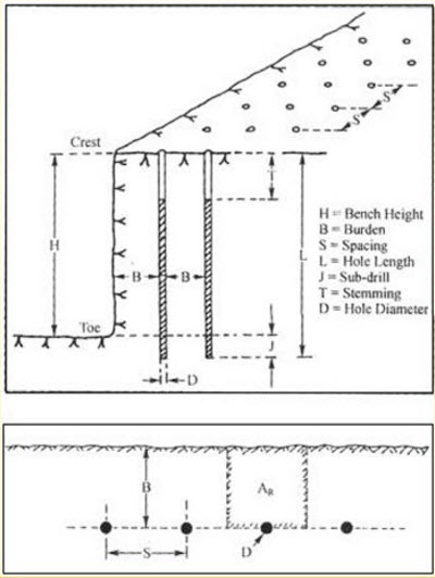
First, please take a look at each of these parameters, as labeled, and make sure that you understand what’s going on. There are two terms on the diagram that we have not yet defined. They are toe and crest. The toe is the bottom edge of the bench adjacent to the vertical wall. The crest is the top edge of the vertical or nearly vertical wall. This wall is often called the highwall.
The equations for determining the burden, spacing, and stemming require that we know the blast hole diameter. So, looking at the diameter of the hole is a good first step. This diameter is defined by the diameter of the drill bit.
For benching, hole diameters typically range from a low of 3” to a high of 15”. If we’re benching in an underground mine, we’ll have hole diameters near the low end of that range, and for surface applications, we’ll be in the middle to upper end of that range. Just as a comparison, I would mention that for drifting, the holes are likely to be as small as 1-3/4” and probably no bigger than 3-4”. In many cases, you will have historical practice or the practices at similar mines to narrow your choices. Other times, you will already own equipment capable of drilling a limited range of sizes, and your design will be bounded accordingly.
Here’s an interesting chart, which is a compilation of the hole diameter and bench height at more than a hundred mine sites. As you can see, there is a rough relationship between the bench height and the diameter of drill used to create the blast hole for that bench.
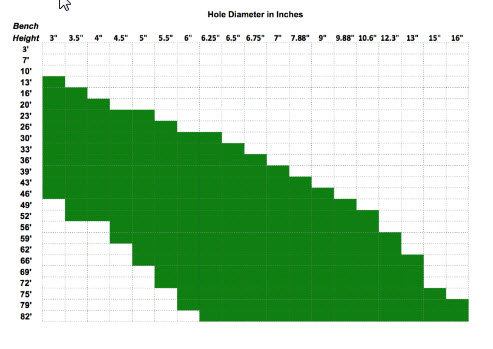
Given a hole diameter, D, we can calculate the burden, B, the spacing, S, and the stemming, T. We will use Ash's to calculate these parameters. Note, as indicated earlier, and as will become more apparent with the discussion of the “K” factors, these relationships provide guidance not absolute precision.
Let’s talk about these “K” factors.
KB = 20 for underground application and 25 for surface, assuming a standard ANFO and a rock density of approximately 2.5 g/cm3. If the rock density is significantly greater or less than 2.5, then the factor should be examined. Here’s a table of typical rock densities for commonly mined minerals. As you can see for most of them, the suggested KB of 30 to 25 will be fine. The notable exceptions would include coal and peridotite. If you need to convert these to lb/ft3, multiply by 62.3.
| Mineral | Rock Density |
|---|---|
| Andesite | 2.5-2.8 |
| Basalt | 2.8-3.0 |
| Coal | 1.1-1.4 |
| Diabase | 2.6-3.0 |
| Diorite | 2.8-3.0 |
| Dolomite | 2.8-2.9 |
| Gabbro | 2.7-3.3 |
| Gneiss | 2.6-2.9 |
| Granite | 2.6-2.7 |
| Gypsum | 2.3-2.8 |
| Limestone | 2.3-2.7 |
| Marble | 2.4-2.7 |
| Mica schist | 2.5-2.9 |
| Peridotite | 3.1-3.4 |
| Quartzite | 2.6-2.8 |
| Rhyolite | 2.4-2.6 |
| Rock salt | 2.5-2.6 |
| Sandstone | 2.2-2.8 |
| Shale | 2.4-2.8 |
| Slate | 2.7-2.8 |
If you are using an explosive, x, with a different bulk strength, the factor KB changes as follows:
KBx = KB * (BSx)1/2, and BSx is the bulk strength of explosive X.
The other two factors are constants: KS = 1 to 1.3; and KT =0.7.
And, that’s all there is to it! More or less… this gives us a reasonable first approximation to laying out the pattern, or at least the burden and spacing along with the stemming. There are additional considerations, as well as sources of additional guidance.
An important metric is powder factor, because it tells us something about how efficient our blast is, and if we know typical powder factors from other similar mines, we can use that number to back calculate some of our design parameters. Powder factor is defined as the weight of the explosive used divided by either the volume or weight of fragmented rock. Its units are lb/ton or lb/yd3, or in the metric system, kg/tonne or kg/m3.
The calculation of the powder factor is straightforward. In practice, you will know how many pounds of explosive were used and you will know how many truck loads of rock were fragmented; and frankly, it is a good idea to keep close tabs on this in your operation. In the design stage, you can directly calculate the powder factor.
The explosive charge per unit length of hole, Mc, is: , where D is the hole diameter and is the density of the explosive. The weight of the explosive in the hole is therefore the product of the charge per unit length and the charged length of the hole, Lc. Remember that the entire hole is not filled with explosive. For example, the top 1/3 or so may be stemming; and in this case, the charged length would be 2/3 of the hole length.
The volume of fragmented rock is taken to be the product of the blast area, Ab, around the hole times the length of the hole. It is defined by a rectangle with the hole in the center. The two sides of the rectangle are and . Or simply, the area of the rectangle, Ab, is the product of the burden, B, and spacing, S. The volume of broken rock is then the area, Ab, times the length of the hole. If we want the weight of the blasted material, we need to multiply this volume by the density of the rock that will be broken by the blast.
The powder factor, PF, is:
All right, we can calculate powder factor, and we understand why it is a useful metric to compute and monitor at our operation. Earlier, I mentioned that knowing factors at similar operations could be useful to us in the design stage. How so?
If we have a known powder factor to start with, we can use that to determine a reasonable burden or spacing, which could be a good “check” on our first round of calculations. We can calculate MC directly based on the explosive that we are going to use and the hole diameter. As a starting point, we can assume that Lc will be 70% of L. We know our bench height, so we know L. The remaining unknowns are B and S. Substituting, we have:
and simplifying,
, and rearranging,
You know MC and PF, but not B or S. However, you can compute the product of B&S; and then, you can choose one, and solve for the other. At this point, you may be thinking: but wait a minute! How is this helping me, because I still have to choose B or S. True, but you are not doing so blindly. You could use B that you calculated earlier with Ash’s formula, plug that number into this equation, and voilà, you now have values for B and S. Or better yet, rather than using the B that you calculated, you might refer to a handbook where you can find burden-to-spacing ratios for many different scenarios. For example, such a table may list a typical S:B ratio of 1.25 for the type of mine of interest to you. Thus, for this ratio:
Substituting this into the equation,
, and simplifying, we have: .
Solving:
And so, using “real-world" data for powder factor and burden-to-spacing ratio, we are able to estimate a reasonable starting point in our design. Please remember that the constant, 0.56, in this equation is only valid for this example.
Here are a couple of other things to keep in mind. The degree of fragmentation will depend on the interrelationship among powder factor, burden, and spacing. We could, as an extreme case, choose to drill one hole of say 48” in diameter and pack in with explosives. The number might look good in terms of the powder factor, but what is likely to be the outcome?
This is why it’s useful to calculate these parameters in different ways, using not only Ash’s formulas but also using the fundamental definition of powder factor and available handbook data.
Clearly, it's a bit of an art, and you will go through iterations before “perfecting” your design. Nonetheless, there is a solid scientific approach to get you reasonably close.
6.3.2: Drift Round Blast Design
6.3.2: Drift Round Blast Design
For drift rounds, we are talking about driving openings, i.e., drilling, blasting, loading, and hauling, in an underground mine. These openings are horizontal or nearly so in many cases, but can be on fairly steep grades in others. Think of advancing a tunnel through a mountain – we are driving an opening through the mountain, and depending on our needs, the tunnel may be inclined or nearly horizontal.
Although the calculations that we just covered are generally applicable, designing a blasting round for drifting is more difficult. There are two reasons for this. Primarily, it is because we only have one free face. In bench blasting, we almost always have at least two. Recall, what is happening in a bench blast. As we initiate the round, the blasted and expanding material closest to the highwall is able to move freely upward and outward in the direction of the highwall. When rock is blasted, it expands by 30% or more, so it needs somewhere to expand. Furthermore, the expanding gases from the detonation of the explosive are rapidly propelling this blasted rock. After the first row of holes has been fired and the fragmented material is moving out of the way, the next row is fired, and the round evolves in an orderly sequence based on the timing delays used in the pattern. If we don’t give the blasted material the space to expand and move, we’ll have a big problem. The fragmentation will be adversely impacted, of course, but the bigger problem is that the fragmented material will tend to stay in place, and then it will be very difficult to dig or load. This is the challenge we face in drifting, because we have only one free face.
We overcome this limitation by creating a second free face; and we do this by putting cut holes in the center of the opening that we are driving. We’ll look at these cut holes in the next lesson, but, essentially, they are unloaded holes drilled in the center of the center of the opening; and then, when this new free face is created, we set off the remainder of the holes. The blasted rock from those holes is then free to expand inward towards this new free face that we created in the center of the opening, and then outward.
We can use the same formulas for drift rounds as we did for designing a blast round for a bench. However, the patterns will be significantly different. And that’s what we really need to look at next – the patterns, i.e., hole placement and timing delays that are used in bench and drift blasting. We’ll do that in the next lesson.
Before moving on to that topic, let me finish one last detail here. I said that drift blasting was more challenging for two reasons, and we just talked about the primary reason for this. The other reason is overbreak, which is fragmentation that occurs beyond the intended space. Suppose you were blasting a tunnel with a rectangular cross-section of 30’ wide by 20’ high. Your goal will be to limit fractures in the rock to the 30’x20’ opening. It’s unlikely that you could maintain a perfect opening, but limiting the fracturing beyond those boundaries to less than several inches is doable. We aren’t as particular about this in many surface applications as we are in underground mines. Why? We touched on this earlier.
These fractures are likely to become future ground control problems, costing us time and money. The fractures or cracks are likely to destabilize over time, and if there is ground water seepage, the process will accelerate. Accordingly, we have to design a round to minimize overbreak. Unfortunately, few engineers do this for lack-of-knowledge; but it is not that difficult, and we will learn how to do it in the next lesson.
Lesson 6.4: Blasting Patterns
Lesson 6.4: Blasting Patterns
We have learned much about explosives, as well as some analytical procedures to help us design blast rounds in surface and underground mines. We know that a blast round consists of multiple holes arranged in certain geometric patterns, and we know that the holes are not necessarily fired at the same time. We don’t know much about these geometric patterns for the holes, nor the time delays that may be used. You will recall from the first lesson of this Module, we watched the video clip, “Dance of the Detonators,” and we saw vivid evidence of different patterns and the use of timed shots. In this lesson, we’ll look at some common patterns, talk about their use, and we’ll look at delayed firing of holes, including the various technologies available to use for this purpose.
6.4.1: Patterns for Drift Rounds
6.4.1: Patterns for Drift Rounds
The overall pattern will be based on the desired shape of the blasted opening. If we are driving headings that will be used by people and equipment to access the ore and conduct the mining operation, we will strive to create openings that will be stable over time, and be of dimensions that meet certain requirements. These requirements may be openings of a minimum height and width to allow equipment access, or the dimensions may be based on production requirements. And there could be other considerations. Rectangular openings have sharp corners that tend to concentrate stresses, whereas elliptical or circular openings do a better job distributing the stress around the opening, and as such, they are more stable. The strength of the rock and the expected life of a particular opening will influence the shape as well as the dimensions of the opening.
The cross-section shown here is typical, but regardless, the content that we are going to cover applies to other shapes as well. Notice that the cross-section is divided into named regions. This can be applied to cross-sections of almost any size and shape.
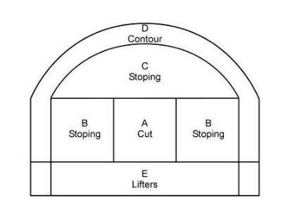
The purpose of the Cut is to create a second free face, which we introduced in the last section of this lesson. There are two general types of cuts: parallel cuts and angled cuts.
The most common type of parallel cut is known as the burn cut. Burn is the shortened name for the Viburnum Cut; so-named because it was developed for use in the lead-zinc mines found in the Viburnum trend in Missouri, back in the 1950s. Its use quickly spread to many underground mines. The burn cut consists of parallel holes, sometimes of different diameters, and always some of the holes are unloaded. The unloaded holes within the burn are referred to as relief holes. Sometimes, a few angled holes are placed within the burn, but this shouldn’t be confused with the other major type of cut, i.e., the angled cut.
Here are examples of burn cuts. The loaded holes are shaded black. The numbers adjacent to the hole refer to the firing sequence. The spacing between the holes is shown for most of them, although the diameter is not. The diameter of the holes would be the same as used for the other regions of the pattern, with the possible exception that the unloaded holes are occasionally of larger diameter. For example, if the loaded holes are around 2”, the unloaded holes of the burn cut may be 4”.
The unloaded holes provide an initial, although quite small, free face. The holes labeled “1” are fired first. The expanding rock moves toward the center and also out in front of the free face. The result is an expanded second free face, and the holes labeled “2” are then fired. They have the benefit of the larger free face, and after they have done their job, there is a sufficiently large free face in the center for the other holes to be fired.
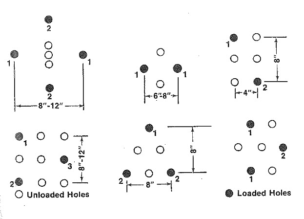
Here is an example of the most widely used angled cut, which is known as the V-Cut. All of the holes are loaded with explosive, which is a contrast to the burn cut. The V-Cut shown here includes a baby V, which is also fairly common. The number adjacent to the holes designate the millisecond (ms) delay for the firing of that hole.
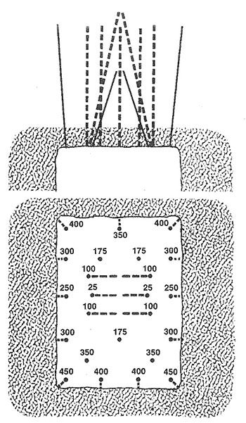
In this example of the V-cut, the baby V fires first, and creates a small free face for the firing of the two large Vs. Then, after the two large Vs have fired, there will be a sufficiently large free face to fire the remainder of the holes. Other variations of angled cuts include pyramidal and diamond-shaped arrangements.
A particular cut will tend to give better and more consistent results in a given deposit. Most underground limestone mines, for example, will settle on a V-cut after trying the burn and V-cuts, whereas in the lead mines in Missouri, there is a decided preference for the burn cut. One of the more important deciding factors will be the pull that can be achieved with the round. Pull refers to how far back into the face you can successfully blast. If we drill a hole, say 12’ back into the face, can we get good fragmentation at the back end of the hole? As you attempt to drill further and further back into the face, it becomes increasingly difficult to achieve good fragmentation near the back of the hole. The distance that you can achieve good fragmentation is known as the pull. It’s important to monitor the pull closely because if a problem has crept into your workflow, whether it is a change in the geology, an inexperienced driller or blaster, or other problem, it will often show up first as a reduced pull.
The stoping holes do most of the work of advancing the face, as they blast the most rock. These holes will begin to fire as soon as the cut holes have cleared, and they will fire in a sequence such that the holes closest to the cut will fire first, and then those further away will fire in sequence. The idea behind the sequencing of the stoping holes is to ensure a good free face for the blasted material to move through.
Lifters are not always used, but their purpose is to help ensure good fragmentation at the bottom of the drift, as this will allow for an even surface that will facilitate movement of people and equipment through the drift. Lifters can also help to throw the blasted material out into the drift to improve the ease of loading.
The holes in the Contour region are designed to ensure a smooth surface and to minimize overbreak. The contour region is properly defined by two rows of holes. The inner row is known as the buffer row, and the outer row at the perimeter of the opening is known as the contour row. Research completed in recent years provides design guidance on how to minimize overbreak using the buffer and contour rows. However, this has yet to be widely adopted.
The delay sequence for a drift heading using a burn cut is shown below. Note that the burn has two angled holes; and also note that the contour region only has one row of holes around the perimeter, reflecting the longstanding practice.
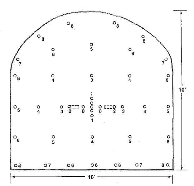
The process of minimizing overbreak is referred to as controlled blasting and is documented in the following publication: NIOSH Report of Investigations 9691, A New Perimeter Control Blast Design Concept For Underground Metal/Nonmetal Drifting Applications [55], Stephen R. Iverson, William A. Hustrulid, and Jeffrey C. Johnson.
We are not going to go through the details of the design in class, but I want you to understand conceptually the process. You have the publication that you can use in the future to design a controlled blast.
This approach requires that significantly more holes be drilled and loaded than in the traditional approach. However, it is rarely about first costs only! You have to look at costs over time, and then make an informed decision. While the first costs of this approach are higher, the improved ground control should yield larger savings over time by eliminating the extensive damage zone into the back and walls.
This approach allows a burden to be calculated between the buffer row and contour row, such that the damage radius from the buffer row does not extend beyond the contour row.
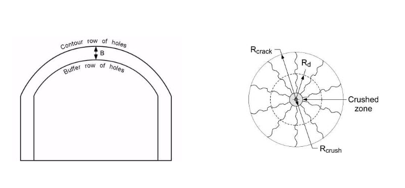
The spacing of the buffer and contour holes is based on the damage radius, Rd, as shown here.
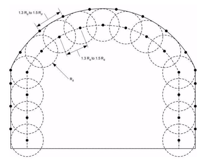
After the buffer and contour holes have been located, the lifters are added. Next, the cut holes are placed, and then, finally, the stoping holes are located. Design guidance for these holes is given in the report.
It is important to note that the contour holes are very lightly loaded. The function of these holes is to trim the wall at that point, not to create additional crushing and fracturing. This is known as decoupling of those holes. There are various ways to load these holes to achieve the desired effect. One way is to use a detonating cord in the hole instead of a blasting agent such as an emulsion or ANFO. Another is to use trim cartridges, i.e., products specifically developed for this purpose.
I think I’ll close this discussion on blast rounds for drifting by showing you a short video clip. The blast will be repeated several times. You’ll want to try to determine the type of pattern that is being used, based on your observation of the detonating cord.
6.4.2: Patterns for Bench Blasting
6.4.2: Patterns for Bench Blasting
There is a seemingly endless variety of patterns, and to make sense of it all, it’s helpful to remember that when all is said and done, the design goal is to achieve uniform fragmentation within a certain size range, and to do this it is necessary to ensure an adequate free face. Most of the variation that you will see in the patterns, and especially for surface mining, will be as result of the way in which the free faces are created and managed. The patterns for an underground bench blast tend to be straightforward – the amount of explosive that will be set off will be far more limited than in almost all surface mine blasts. As you attempt to blast larger and larger volumes, you need more holes, more rows, and the timing delays become more involved.
Here is a common surface mine layout with one free face. The numbers underneath the hole correspond to the delay sequence, first, second, third, and so forth. The numbers over the holes represent the millisecond delay for that hole.
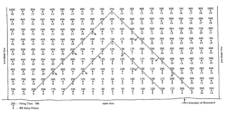
If there are two free faces, as in this case, a pattern like this is common.
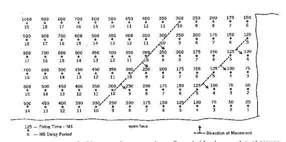
Occasionally, it is necessary to design a surface blast where there is no free face. Imagine an open field, and you are going to make the first blast so that material can be removed to initiate the surface mining cycle. By the way, the name given to this is box cut. Box cuts are a common means of accessing an orebody for underground mining, when the deposit is within a few hundred feet of the surface; and they are required as one of the initial development steps in most surface mining operations. A blasting pattern for a box cut is shown here.
These patterns can and will be modified ad nauseam to account for local geological anomalies, nearby structures such as pipelines or buildings and so on. With the few figures that we’ve examined here, you really do have comprehensive starting point for the design of your own pattern. You know how to: determine the burden, spacing, and stemming; choose an explosive or blasting agent; and lay out a pattern. One glaring gap in your knowledge base is how to achieve the desired timing delays. And so, we need to talk more about initiating the blast and the technology options available to us. We’ll do that in the next lesson.
Lesson 6.5: Fire in the Hole
Lesson 6.5: Fire in the Hole
Prior to setting off a blast, the blaster would yell, “fire in the hole – fire in the hole – fire in the hole.” This still occurs today, but not as frequently because loud sirens or whistles are often used instead. After the annunciation, whether by voice or siren, the blaster throws the switch or depresses a plunger to set off the blast. Or, in the good days, a third option would have been to strike a match or light a fuse! But what is going on here?
We know that we need an “initiator” to set off an explosive, something like a blasting cap for example. However, we also know that many of the blasting agents in common use today are not cap sensitive, and consequently, we need to use a primer. The cap, or whatever initiator we use, sets off the primer, which then sets off the blasting agent or explosive. Finally, you will recall that there are times when we are concerned that the explosion will not continue due to the length of the explosive column or the use of decking, for example, and in those cases, we add boosters. And in some cases, we will actually have multiple boosters in the hole.
We’ve talked at length about explosives. Now, let’s spend some time with initiators!
6.5.1: Initiation of the Blast
6.5.1: Initiation of the Blast
Initiators contain high explosives that will detonate upon receiving an appropriate “signal.” If the blasting agent is cap-sensitive, then this action will set off the explosion. If it is not cap-sensitive, then the initiator will set off a primer, which will set off the blasting agent. In a typical pattern, there are many holes and each will have an initiator, and all of these holes need to be connected together, and a line must then be run to a safe location where the blaster will “throw the switch.”
Let’s talk about these initiators, their connection back to the blaster, and the method that the blaster uses to start the chain reaction.
Initiators can be classified into three categories. The categories and their primary characteristics are as follows:
- non-electric (75% of market and decreasing):
- immune to stray electricity,
- water is less of a problem than with other types,
- modest cost advantage, i.e., lower cost than other types;
- electronic (20% of market and increasing):
- allows for precise timing and sequencing,
- enhanced site security,
- immune to stray electricity,
- higher first cost and more complicated to use;
- electric (5% of market and decreasing):
- historically offered better control of timing and sequencing over non-electrics,
- simplicity in use,
- lack of site security,
- susceptible to stray electricity.
Non-Electric Initiation
The predominate non-electric system uses shock tube and a non-electric blasting cap. Shock tube is plastic tube with a thin coating of a high explosive (think of a plastic drinking straw in which the inner wall of the straw has a thin coating of high explosive). Specially made plastic block connectors are used to join different lines (shock tubes) together; and, if desired, delays can be inserted at these connector blocks as well. Shock tube is set off with a machine that creates a spark or a mechanical device such as a spring-loaded hammer that strikes a starter resembling the tiny button primer at the base of a shotgun shell. Today, shock tube is used almost exclusively within the non-electric category. I don’t want to unnecessarily confuse the issue, but be aware that the nonelectric blasting caps used with shock tube can contain a pyrotechnic or an electronic time-delay mechanism within them. We’ll discuss blasting caps, both non-electric and electric, shortly.
Detonating cord contains a high explosive, such as PETN. It was used for trunk lines and downlines. Lines can be simply knotted together. It is initiated with a blasting cap (electric or nonelectric). The detonation velocity of PETN is 27,000 fps, and it creates a huge air blast. This is a big problem, and as a result, detonating cord has been largely replaced with shock tube.
There are two other types that no longer used in modern operations, but it's interesting to know what they are in case you read or hear about them. They are safety fuse and igniter cord. Allow me to tell you a bit more about safety fuse.
- Safety Fuse is a thin cloth fiber cord with a black-powder core. It has a uniform burn rate, for instance120 sec/yd. By varying the length, you could vary the time delay. Safety fuse was used to set off dynamite. It was also used in a lot of bad old cowboy movies in which a bad guy tied the good guy to a powder keg, and the powder keg was connected to a very long safety fuse. The bad guy lit the safety fuse and rode away. Since the safety fuse burns so slowly, the viewers got to watch it burn for a few minutes, giving the hero just enough time to swoop in and extinguish the safety fuse before it set off the powder keg!
Electronic Initiation
The popularity of electronic initiation is increasing because this system offers significant performance and safety advantages over other systems.
- Electronic caps consist of an electronic chip, a small capacitor, and a high explosive to detonate a primer or a cap sensitive explosive.
- Each electronic cap has a unique serial number with a bar code.
- Electronic caps are wired into the blasting circuit with insulated copper wire.
- An electronic blasting machine is required, and it communicates digitally with each cap.
- The electronic blasting machine is programmed to send a “fire” signal to each cap, based on the cap's serial number, according to a user-determined firing pattern.
- The wired circuit connecting the electronic caps together and to the blasting machine also carries an analog voltage to charge the capacitor in each cap. Charging of the capacitor begins after the blasting machine has “authorized” the cap to fire. The capacitor provides the energy to detonate the high explosive within the cap assembly. The authorization to each cap is possible because the unique serial number of each cap is known. The blaster can use a tag reader to record the serial number of each cap as each hole is loaded. This data can then be downloaded to the blasting machine.
- The time delay is determined electronically on a chip, and this is known as an electronic delay.
- The more precise timing and sequencing can be used to minimize ground vibration as well as to improve the outcome of the blast…but only if the underlying shot design is correct. The improved blasting performance available with an electronic initiation system will offset the higher initial cost of the caps.
- This system affords the user with a high degree of site security – a cap cannot be set off without a special machine and knowledge of the cap’s serial number.
It should be noted here that there is a type of electronic blasting cap that is made for use with shock tube, and that cap offers the advantage of more precise timing, but it does not offer the other benefits inherent to an electronic ignition system.
Electric Initiation
For decades, electric blasting caps were the only choice if you wanted to control more exactly the time delays. However, their susceptibility to stray electricity (think cell phones, two-way radios, and approaching electrical storms) has led to their rapid decline.
- Electric blasting caps have a bridge wire inside of them, embedded in a high explosive. When current from the blasting machine, or stray electricity, flows in the network of copper wires, the bridge wire melts, igniting a column of powder that controls the delay time, which then sets off a high-explosive base charge. This is known as pyrotechnic ignition. The base charge sets off a cap-sensitive blasting agent or a primer.
- The blasting circuit consists of many wires connected in series and in parallel, e.g., leg wires and trunk wires. A circuit analysis must be performed to ensure that sufficient current will be available to ensure a reliable blast.
The following diagram can be very helpful to solidify your understanding. The two different delay options, i.e., pyrotechnic and electronic, can show up in different initiation systems. That is sometimes confusing when you are learning this for the first time. Thus, it really is helpful to examine this diagram until you understand the operating principles and why they are named the way they are.
Historically, time delays were used to control the orderly movement of material through the free faces, as we have discussed; or to limit the amount of explosive being fired at any one time, which reduces the level of ground vibration. The advent of electronic initiation ushered in a new era in which we could more effectively take advantage of the physics.
Traditionally, time delays were available in 25 ms delays, which is adequate for the purposes that time delays have been used. The p and s vibration waves are shown in this figure for two cases: the first using traditional delays; and the second, using electronic delays that allow timing down to 2 ms. This allows us to create a positive interaction with the shock waves, and this gives us improved fragmentation.
It can be shown that the time delay, T, required between holes in a row is:
where:
T = the time delay between holes in a row, ms
S = distance between holes in a row, ft
Vp = compression or sonic wave velocity, ft/s
The row spacing distance used in the equation is the effective spacing, as shown for three different cases here. Note that the definition of a “row” is based on the firing sequence.
The value for Vp can be estimated from tables or by seeking advice from geophysical consultants. The value for Vp not only depends on the type of rock, but also the rock mass characterization. There are a few different characterization schemes in use, such as the Rock Quality Designation (RQD) or the Rock Mass Rating (RMR), but, in general, they take into account the number and spacing of the joints, the competency of the rock, and other characteristics of the rock mass. If you want a number for Vp so that you play with the equation, use 10,000 fps.
The potential for using electronic initiators to take advantage of the wave interaction is just being realized, and will become more common in the future. You now have knowledge of this, and can choose to take advantage of it in your future work.
Earlier in this lesson, I mentioned the idea of limiting the amount of explosive detonated in a given delay interval to lessen the impact of ground vibration. I’d like to look at that in more detail at this time.
6.5.2: Limiting Ground Vibration - Scaled Distance
6.5.2: Limiting Ground Vibration - Scaled Distance
Humans are very sensitive to vibrations and can perceive extremely low levels; and while this may have been an invaluable survival skill a long time ago, today it creates problems for mining and construction companies wanting to conduct blasting as part of their operations. Please don’t misunderstand me: I am not suggesting that we should blast in a way that causes any property damage. Unfortunately, the difference between the level at which people “feel” vibration and the level at which damage occurs is large. Consequently, when people feel vibration, they assume the worst. They look around the house and see a picture on the wall that is no longer straight. Had to be those vibrations! They look more closely, and they see some fine cracks in the plaster on the wall. Well, that’s it; we’ll have no more of this, they’re going to bring down our house!!! Then the angry phone calls, letters, and confrontations with company officials begin. Sometimes, citizens groups emerge, and usually local and sometimes state officials become involved. Mining companies spend more time and money dealing with this than they should! Oh, and when I say mining companies, I mean YOU. If you go to work in a surface mine, chances are good that in your first few years on the job, you will deal with this. So, what’s a person to do?
I have five recommendations.
- First, and foremost, you have to get the engineering right! You have to design your blasts correctly. We’re going to learn how to ensure that the ground vibration levels from your blast are below levels that could create any damage.
- Second, you have to ensure that the drillers and blasters are executing the blast as you designed it.
- Third, you need to be “smart” about when you blast. Most surface mines that are in close proximity to neighborhoods blast once a week. You’re likely to create fewer problems with the neighbors if you blast late morning or early afternoon on a weekday. Blasting around dinner time is a bad idea, as is shooting a round on the weekend!
- Fourth, you and your company should work to have a genuine and positive relationship with the community, as we discussed way back in Module 1. That will help you to navigate these kinds of issues, and, moreover, you may need to spend some time educating the locals on this topic. In fairness to them, they feel the vibrations and they are worried that you are going to damage their house. If they were structural or mining engineers, they wouldn’t be concerned, but they are not, and they are concerned! Educate and inform!
- Fifth, you should give serious consideration to contracting with a consulting geophysical firm that specializes in blasting vibration. They will help you to set up a seismic monitoring program and provide other guidance. Sometimes, neighbors will file damage claims, or raise regulatory issues; and this will happen even though you are certain that the vibration levels were well below any damage threshold. Obviously, you want to ensure that you are not actually causing a problem, but beyond that, you’ll want to establish a paper trail to document that you’ve been doing it properly, and that you could not have caused the loss that is being claimed. And, that's where a geophysical consultant can be a big help to you. There is a company based here in Pennsylvania known as Geosonics / VibraTech. They provide services internationally and are active with our Department and our chapter of SME. I recommend that you peruse their website to get a better feel for the type of services that mining companies use. Here is the link: GeoSonics/Vibratech [56]
Now, I want to focus on the engineering.
Ground vibration at a remote location is a function of the amount of explosive set off within a short time period (a few ms) and the characteristics of the rock mass between the blast holes and the remote location. You cannot change the local geology, and if you are mining stone, for example, it is a safe bet that the rock in your quarry is solidly coupled with the surrounding community; and as a result, any vibration that you create will travel quite well through that bed of limestone to the surrounding neighborhoods.
You can’t change the rock mass. That leaves the amount of explosive fired in a short time as the parameter that you can control. An explosive works by creating shock waves and gas pressure. The more explosive that you set off, the larger the shock wave, which travels through the coupled rock mass, and causes ground vibration. So, by limiting the amount of explosive set off at any one time, you can limit the shock wave. Within a few thousandths of a second, the shock wave will have dissipated, and then you can set off the next group of holes. Earlier, we talked about using time delays to create and effectively use the free face(s). Now, we’re adding a second reason for using time delays in a blast round -- to limit ground vibration (and also airblast).
We characterize the shock wave by its peak particle velocity (ppv) and the frequency of the wave. Both are important, but most of the attention is given to the peak particle velocity. Rattling of windows and dishes, or cracks in a wall can be related to the peak particle velocity. The design question for us is, how much explosive can we fire at one time without exceeding the threshold ppv value at the nearest structure?
We could model the rock mass and use sophisticated geophysical models to predict the level, and there are a few instances where such an effort would be warranted. For example, if the nearest structure is a building that has a piece of multimillion-dollar lab equipment that is extremely sensitive to low levels of vibration, then, we’re going to call in expert consultants, e.g., Geosonics, to perform the analyses. Fortunately, in most cases, we can use engineering approximations. These are normally very conservative, and after we gain some experience with the pattern, we may be able to increase the amount of explosive per time delay with no adverse impact on neighboring structures.
The U.S. Bureau of Mines developed an approximation method, known as scaled distance, to estimate the amount (weight) of explosive that would produce a certain ppv at a specified distance. Over time, this method has been adopted by state and federal regulatory agencies, and these agencies have regulations that require that ground vibration be limited based on either the scaled distance or the peak particle velocity of the shock wave. Usually, you would use the scaled distance to calculate the amount (weight) of explosive that can be fired without exceeding the statutory limit, which is typically a peak particle velocity of 0.5 in/s.
The Bureau of Mines (USBM) conducted hundreds of tests at different surface mines. The sites and surrounding areas were heavily instrumented to record the amplitude and frequency of the vibrations from blasts of varying size. Eventually, they developed a relationship between the peak particle velocity and a quantity they defined as scaled distance.
The scaled distance, S, is a function of the distance to the nearest structure, D, and the charge weight, w, fired within an 8 ms interval.
The units for D and w are ft and lb respectively. The unit for scaled distance, S, is therefore
Rearranging the equation to solve for the charge weight:
If you know the distance to the nearest structure and the scaled distance, you can calculate the charge weight that can be detonated in one delay period without exceeding a particular vibration level. So, let’s look at a plot describing the relationship.
This is a plot of the USBM data points, and each point is defined by the measured peak particle velocity (ppv) and the scaled distance. A good correlation exists as shown. They are actually plotting data from three different geophones, i.e., seismic sensors. The line of interest to us is the one labeled “vertical” because it represents the ground vibration level of interest to us at the structure we are trying to protect.
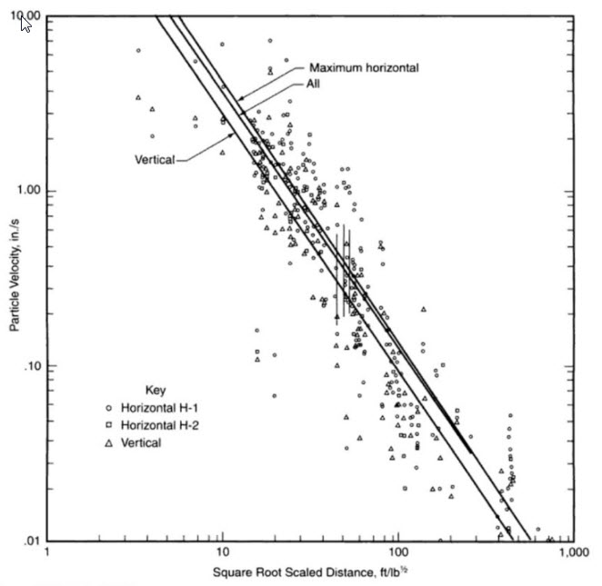
To continue with our example, let’s say that the nearest structure, which we do not own, is 2500’ from the bench that we are going to blast. The statutory limit for this mine is 0.5 in/s. What is the maximum charge weight per delay period?
Maximum charge weight/delay period:
The computed value for w is the total weight of explosive that can be detonated within a prescribed delay period, which is typically 25ms. Based on the amount of powder in each hole, you can then calculate how many holes can be fired at one time. Suppose, for example, that each hole is 5” in diameter, 45’ deep, and requires 10’ of stemming; and you are using ANFO with a density of . How many holes could you fire at one time, without exceeding the prescribed vibration limit?
The charge weight per foot of hole =
The charge weight per hole =
The maximum number of holes per delay period =
= 9.9 holes.
How accurate is this estimate? We need to understand the assumptions underlying the scaled distance chart. The chart is based on the use of a dry ANFO. If a more energetic blasting agent or explosive is used, the chart will overestimate the amount of powder that can be fired at one time. The USBM field sites were predominantly surface coal mines and some quarries. Depending on the local geology, the chart will overestimate the amount of powder. An overestimation of the amount of powder translates directly to an increase in the ground vibration level, which could put you in violation of state-regulated maximum levels. So, what good is this approximation if it can lead to significant overestimates? Simply, it provides a good starting point for your design. Further, in Pennsylvania for example, the state agency requires you to start with a scaled distance of 90. It is unlikely that you would ever have to worry about an overestimation at that distance!
Our discussion has focused exclusively on ground vibration. A similar approach is used to limit airblast. A different chart is used becuase the relationship between air blast and distance is cubic rather than squared. If we were to use the companion chart for airblast, we could go through an almost identical process to determine how many holes could be fired within a delay period without exceeding the airblast threshold. We’re not going spend any time doing that, but if you have the need at a future time, I am sure you could do that without any problem!
OK, let’s recap the engineering design of the blast round, as described in the recent lessons.
- The design is guided but not fully defined by science. Practical experience is invaluable in optimizing the design. If you don’t have that experience, the people who sell blasting products often have a wealth of practical knowledge and are happy to share it with you. Of course, they will be hoping for your business!
- The design process is iterative. You start out assuming certain parameters and calculating others. You compare the numbers that you are generating with handbook or literature values. Then, you rework some of those initial calculations with modified values, which generates results more aligned with the practical experiences of others. In particular, you will likely start by establishing values for the hole diameter, the burden, spacing, and stemming. Likely, you will locate typical powder factors and burden to spacing ratios in similar applications. You may then “fine-tune” your burden and spacing values, and perhaps reevaluate the diameter of your borehole.
- You will lay out the pattern of the holes based on free-face requirements, and you will assign holes to specific delay intervals.
- If you are blasting in proximity of structures that must be protected, you will assess ground vibration and airblast potential. It is likely that you will then alter your timing to limit the number of holes that fire within a given delay period.
- A reasonable next step would be to drill some holes and evaluate your design, keeping in mind that even if you are completely satisfied with the outcome (highly unlikely), you should be evaluating the outcome of your blasts on a regular basis, day-after-day, week-after-week, and month-after-month!
- We saw earlier in this lesson that you can use the precise timing of electronic delays to further improve fragmentation, and probably with less explosive. If you were going to pursue that in your design, you would then calculate the appropriate delay between holes in the row. Keep in mind that these delays would all occur within the large delay period that is based on managing your free faces and limiting ground vibration or airblast.
- There will be other reasons why you will need to modify your design over time. If you are experiencing fragmentation issues with cap rock, for example, you will utilize a set of design criteria to resolve them. If there is a big mud channel or fault running through your property, it will necessitate serious changes in your design. Those details are well beyond the scope of this course, but with your engineering fundamentals background and the knowledge that you’ve gained here, you’ll be able to handle those problems as they arise.
In the next module, I am going to show you photos taken at mine sites around the country to illustrate many of the basic concepts that you’ve studied in this module.
Module 6 Summary
Module 6 Summary
Blasting is an important part of almost every mining method, and the responsibility to design a safe and effective blasting pattern lies with the mining engineer. There are a variety of blasting agents and technologies available to accomplish the task, but they must be selected and applied correctly. As we saw, blasting is both an art and a science. The science guides our design, but in the end, experience and judgment will allow us to optimize the outcome. Importantly, we saw that the skill of the drillers and blasters will affect the outcome of the blast. Errors or carelessness in drilling and loading, for example, can cause terrible outcomes. Changes in the local geology can quickly change the outcome of the blast, and these changes are usually not for the better! It is therefore essential that the mining engineer follow up on a regular basis to inspect the outcome of the blasts, and to make changes to the design or implementation. The cost of drilling and blasting is significant, and you will want to take steps to ensure that you are controlling these costs. Do not forget, however, that your blasting practice can significantly influence your overall productivity by affecting other auxiliary and unit operations ground control to loading. Inspection, measurement, and calculation of your blasting outcomes, on a frequent and regular basis, is important!
Matt B Practice
ASSESSMENT TIME:
More Matt B. Practice Questions:
Module 7: Surface Mining
Module 7 Overview
Module 7 Overview
The vast majority of minerals, by tonnage and type, are recovered from surface mining activities. As you know, surface mining is used to recover near-surface mineral deposits, where it is economically feasible to remove the overburden to gain access to the minerals of interest. Surface mining is typically a large scale and bulk operation. In general, the surface mining methods are the lowest cost of any mining methods. Of course, some minerals of economic interest lie too deep to be economically recovered by a surface method, whereas others cannot be mined by a surface method because of environmental or social constraints, which necessitate using an underground mining method to recover those deposits.
Let’s take a look at the number of surface vs underground mining operations for each mining sector in the US.
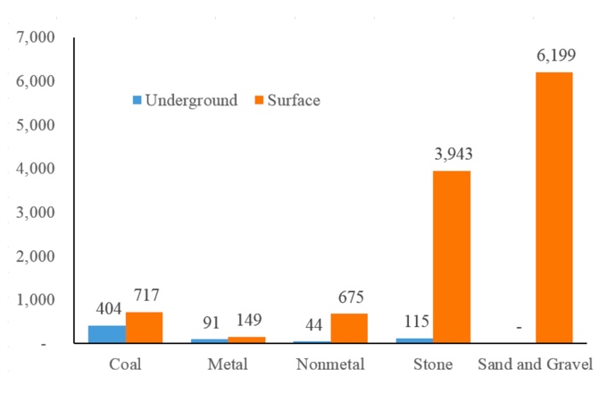
Click to expand to provide more information
| Sector | Underground | Surface |
|---|---|---|
| Coal | 404 | 717 |
| Metal | 91 | 149 |
| Nonmetal | 44 | 675 |
| Stone | 115 | 3943 |
| Sand and Gravel | 0 | 6199 |
Not only are there more surface than underground mines, but also the average productivity is higher for surface operations. The average productivity (average tons per miner per hour) for surface mining is around three times the value for underground mining. Here is a summary of coal mine productivity for different years (the values are tons per miner per hour) to illustrate the difference in productivity, as well as changes that have occurred over the years.
| Year | Underground | Surface | All Mines |
|---|---|---|---|
| 1980 | 1.21 | 3.27 | 1.93 |
| 1990 | 2.54 | 5.94 | 3.83 |
| 2000 | 4.15 | 11.01 | 6.99 |
| 2010 | 2.89 | 9.47 | 5.55 |
| 2015 | 3.45 | 10.95 | 6.28 |
The depth and breadth of engineering required for surface as compared to underground mining is arguably significantly less. Nonetheless, good engineering is the key to sustainable operations; and it all begins with mine planning.
Learning Outcomes
At the successful completion of this module, you should be able to:
- demonstrate knowledge of the goals of long-range, short-range, and production planning;
- demonstrate an understanding of the Mathieson list of objectives for the extraction planning process, and explain in specific terms how those objectives would affect planning and mining activities;
- lay out a bench for an open pit mine, labeling the toe, crest, the face angle, bench width and height, face angle, slope or pit angle, and the berm location and height. Describe the parameters and considerations that will affect the design of the bench;
- demonstrate knowledge of the mechanical and aqueous surface mining methods, and specifically for each method:
- describe the factors that favor the choice of the method over other methods,
- describe the life cycle and sequence of operation,
- sketch the method to illustrate its defining characteristics,
- list the type of equipment normally associated with the method, and
- name examples of commodities that are commonly mined using the method.
Lesson 7.1: Mine Planning
Lesson 7.1: Mine Planning
We are going to talk about mine planning in this lesson, and the focus is on surface mining. However, almost everything that we cover is equally applicable to underground mine planning, even though the examples that I use here are taken from the surface rather than the underground application.
What do we mean by mine planning, and why do we do it. As to the first question, mine planning is a combination of mine design and scheduling of mining activities. The short answer to the second question is: we need to align our mining activities to meet the financial expectations of the company or its investors. We’ll look at both of these in more detail.
Mine planning involves both mine design and scheduling of mining activities.
The goal of mine design is to create a mine that will allow exploitation of the reserve in a safe, economic, and environmentally responsible manner. This design will reflect the unique characteristics of the deposit, anticipated market for the product, and the profit expectations for mine.
Mine scheduling, on the other hand, is concerned with the sequencing of operations and the assignment of equipment and people to ensure that the intended sequencing and production targets are realized. For example, if you dispatch an electric shovel and trucks to remove ore, but the dragline has not yet removed the overburden overlying the ore, you will have a problem… and you will probably be out of a job! Mine planning is performed over many different time horizons. When you are doing your initial feasibility study, you will look at a life-of-mine time frame, which might be 30 years, and as your planning progresses, you will focus more on the first five years; and once the mine is open, you’ll be looking at time frames as short as this shift or the next few shifts. Not only is mine planning an on-going activity, but the planning for the different time horizons is ongoing.
This can be summarized in the following table:
| Type of Plan | Cycle for Updating the Plan | Period Covered by the Plan |
|---|---|---|
| Long-term | Annually | Life-of-mine |
| Medium-term | Quarterly | 3 years |
| Short-term | Monthly | 3 months |
| Daily | Daily | 48 hours |
Let’s think about what this table is telling us.
The long-term plan is updated annually, and, basically, we want to know when it will be time to close the mine. We’re also interested to see the projected production levels in future years so that we can assess profitability as well as our ability to meet market demand. We’ll define a medium time horizon, and this will vary by commodity, company, and life of mine; but a typical horizon is three years. We’ll update this quarterly, and this planning will inform equipment purchases and other capital decisions. Our short-term plans will be concerned with detailed mining plans, e.g., where we will mine next and sequencing, how much production we’ll get, detailed equipment, supply, and personnel needs, detailed supply costs, and so on. Our daily planning will look forward over the next few shifts, and establish detailed staffing plans and equipment assignments. In a nutshell, that’s mine planning.
Now, let's add just a bit more detail to this.
7.1.1: Mine Planning Details
7.1.1: Mine Planning Details
Mine operators want to maximize profit while ensuring safe and environmentally responsible operations. There are many constraints that will limit the profitability of a mining project. Many of these constraints are not well known at a given point in time, and some of them can change unpredictably over time. These uncertainties create risk, and this creates complexities for mine operators. Major uncertainties for a mining project are grade, tonnage, and geotechnical conditions, as well as economic-related uncertainties such as fluctuations in price and demand for the mined product.
Good mine planning throughout the life of the mine is an essential prerequisite to realizing the financial goals of the project. Moreover, it is very important for you to appreciate the time value of money. Simply put, the value of $1 today is much higher than the value of $1 that will be received in the future. We use a metric known as the net present value, which allows us to compare future revenues or costs at the same point in time. Suppose, for example, that your project will produce $100 of revenue this year, $500 in year 5, and $1000 in year 10. My project will produce $600 this year, $600 in year 5 and $100 in year 10. Let’s say that each project requires you to make the same investment today, to realize these revenue streams. For this illustration, the amount of your investment is immaterial, but it is the same for both of them. Which project is the better investment? On the face of it, your project appears to be the better investment. Over ten years, it will return $1600, whereas my project will return only $1200.
However, this comparison neglects the time value of money. If I have money in hand, I can put it in the bank and earn interest, for example. Let’s suppose that the interest rate is 10%. Then, the question becomes what amount of money would I have to invest today at 10% so that in 5 years it would equal $500. In other words, what is the present value that will accumulate to $500 if it earns 10% interest each year for 5 years? The answer is $310. In other words, that future earning of $500 is only worth $310 today. What about the $1000 that you expect to earn in 10 years? It has a present value of $385. So, the present value of your project is ($90+$310+$385), or $850. The present value of my project is ($545+$372+$38), or $955. Thus, the value of my project is better than yours, based on the net present value. The interest rate that we use for this calculation is also known as the discount rate. As you can see, the present value of a dollar earned far in the future is very little. Further, who knows what the world will look like in 10, 20, or 30 years? So much can change. For these reasons, the decision to move forward with a project is influenced heavily by what happens in the first five or so years of operation. For now, do not worry about the calculation of present value, but only the concept of present value and how it influences mine planning and investment decisions.
In MNG 412, you will learn about several economic tools to evaluate the merits of a project, and net present value is only one. Payback period, discounted cash flow, internal rate of return, among a few others, will help to inform a decision on the worthiness of a given project. Regardless, without accurate mine planning, the investment calculations will be of little value!
As a general rule, if we are to maximize the project’s profitability, we need to maximize its net present value. Based on this concept, it makes sense that we plan our mining activity to recover the part of deposit that will yield the highest profits earliest in the life of the mine. Profit is determined by subtracting cost from income:
Profit = Income – Cost
In today's mining industry, it is the income or cash flow generated in the first 5 to 7 years of the mine life that will either make or break a surface mining operation, not the remote economics of the ultimate pit limit, which is usually at least 20 years away. Therefore, if we want to maximize profit, we have to define two objectives: (1) maximize the income and (2) minimize the cost.
How do we maximize income?
- by mining out the highest grade of material as early as we can
- by mining out as much material as we can sell at the earliest possible time
What are some of the ways to minimize the cost?
- minimizing waste removal operation
- minimizing the cost of the unit and auxiliary operations
A question that may rise in your mind is: Why don’t we use a couple of huge pieces of equipment to extract all of the ore during the first year, instead of spending say 15-20 years in one operation? Actually, that is a good question at this point. Here are some reasons why that strategy isn’t practical.
Insufficient Market Demand
It is unlikely that we would be able to sell all of the product in a short time. Therefore, we would incur expenses in the present year, but not receive income to offset those expenses until a future time. Given the time-value-of-money discussion that we’ve had, we certainly don’t want this. Moreover, when you have product to sell, but no buyer, you incur additional “penalties.” Namely, you are taking up space around your plant, or you are incurring a charge to “store” the material elsewhere; and the quality of your product may deteriorate as it lies around.
Increased Equipment Costs
The purchase price of equipment increases with size and can become disproportionately more expensive if the piece of equipment is not in a common market range. Therefore, a small fleet of very large equipment will cost us much more than a larger fleet of smaller equipment of common size with the same overall capacity. However, the unit operating cost, which is the sum of maintenance and operating expenses for a fleet of very large equipment can often be significantly lower than a large fleet of small equipment.
Years ago, mining companies believed that bigger equipment is always better. Their reasoning was that even though the ownership cost is greater for bigger equipment, the unit operating cost is lower. Therefore, the overall unit cost, which is the sum of the unit ownership and unit operating costs, of the bigger equipment will be lower. It was true, to some extent. However, if a single piece of large equipment breaks down for a couple of hours, it will significantly delay production. On the other hand, if we have a fleet of smaller pieces of equipment, even if one needs maintenance, the rest of the fleet can generally cover its absence. Moreover, the unit operating cost of bigger equipment, especially the maintenance cost, dramatically increases as the equipment ages. Consequently, the “bigger is better” strategy must be carefully analyzed.
Higher Mine Development Costs
If we want to use really big equipment, then we’ll have to change the design parameters of our mine. Larger equipment requires sufficient space to operate. For example, if we’re talking about a larger truck, the haul roads will need to be wider, and we’ll need a better road bed and bearing surface, i.e., a more expensive haul road that will remain stable under the heavier truck weight. Wider roads in a pit will necessitate a higher stripping ratio, since the pit walls will be pushed back to the waste area, and this will increase the mine development costs.
Consider this figure in which we have an orebody shown in blue and two different pit limits for two different roadway widths. The blue pit limit corresponds to a wider road than the orange pit limit. As you can see in the below figure, the blue pit needs additional waste removal equal to the dashed area, compared to the orange pit. Therefore, more waste is now mined out per ton of ore, and the stripping ratio will be higher.
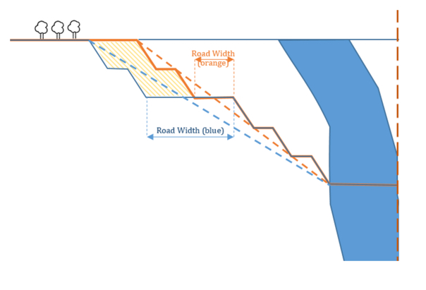
Loss of Selectivity
We talked earlier in the course about selectivity, and you will recall that selectivity is a measure of how effectively we can extract the ore of interest while taking as little waste material as possible. Larger mining trucks need to be matched with larger loading equipment; and larger loading machines have larger buckets. A large bucket reduces selectivity in loading, and that means you will dilute more of the ore with waste material than with a smaller piece of loading equipment.
This effect can be illustrated by considering the block of ore shown here, in Figure 7.1.3(a), assume that we have two options to load the material: a large bucket shown by the blue outline in Figure b and a small bucket the size of the blue outline in Figure c. With the large bucket, we will load all of the ore in the block, shown in orange, as well as the waste material shown in white. With the small bucket, we can be more selective, and taking three small bucket loads we get all of the ore with far less waste. As you can see, the option with the small bucket will reduce the dilution, and this in turn will reduce the unit cost of production.
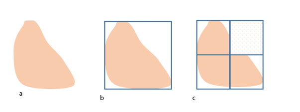
Equipment Life Cycle
The service life of mining equipment is measured in tons, hours, or years, depending on the type of equipment. A haul truck might have a life of 100,000 hours of operation, which may translate into 15 years of service life at a particular mine, and maybe as much as 20 years at a different mine with a different work schedule. Given the high capital cost of mining equipment, much effort is given to match the life of equipment with logical periods of production at the mine. This is yet another reason why mine planning is so important, to ensure that maximum benefit can be obtained from every piece of equipment over the life of the mine.
It is vital for a mining operation to determine an operationally viable mining sequence for the deposit and, subsequently, a production schedule that is achievable and economically sound. The Mine Planner's objective is to schedule and plan operations to achieve maximum return (of profit) on investment, through capital investment (e.g., mobile equipment), mine design, production scheduling, and preparation of the mineral product according to specifications that are required for the market. Therefore, “quantity” and “quality” would be important “drivers” in mine production planning.
BEFORE MOVING ON TO THE NEXT LESSON, please take a little time to think about the concepts presented in this section of this lesson. These will be underlying themes in many other topics.
7.1.2: Mathieson's Planning Objectives
7.1.2: Mathieson's Planning Objectives
We’ve talked about the economic foundation of mine planning, and we’ve looked at several examples of how the mine design and the mine schedule can affect the economics. This is a good foundation for understanding the material in this course, as well as preparing you for more detailed studies in later courses. I want to conclude this lesson on mine planning by presenting a list of objectives to guide your mine planning decisions.
The starting point for your mine planning activities will be the geological model of your orebody; and this will be true, regardless of whether you have come into the planning process at the startup of the new mine, or after the mine has been in operation for years. You will have a block model, which details the grade of the ore in discrete categories and locations. The size of the blocks and the number of categories is a separate decision, but one that does not need to be addressed here. Consider this block model, which uses one of five grade ranges for each block. So, this is your starting point – where do you go from here? Undoubtedly, your approach will be multifaceted. There is a set of planning objectives first compiled by Mathieson and published in 1982. These objectives apply more or less to underground as well as surface mining, although his famous paper was directed at the surface mining community.
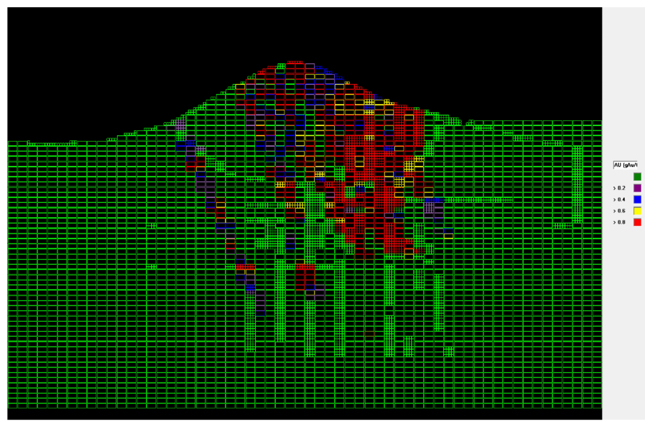
Here is a list of the major objectives of any surface mine planning exercise at the feasibility level:
Mining the “Next Best” ore
Mine orebody in such a way that for each year the production cost to produce a given amount of final product is minimized. What do we mean with the “Next Best”? The next best ore block here is the block that (i) maximizes the profit and (ii) does not contradict any other constraint or limitation, e.g., equipment operating room and slope design. To find the “next best” in the above figure, we will look for the red blocks that are close to the surface. We chase the red blocks because they contain a higher grade of ore that is easiest to mine. What do I mean by easiest to mine? I mean minimizing the production costs, and this normally suggests closest to the surface without any complicating factors. A complicating factor would be an environmental constraint or a geologic anomaly, for example.
Maintain sufficient ore exposure
Give yourself options on which mining face or faces will be scheduled for production on a given shift. If you normally have five active faces on any given shift, then you will want to have at least ten faces available for work on any given shift. Then, if there are unexpected ground control or other problems, you can simply move active work to a different face. Moreover, mining operations try to maintain enough ore exposure to meet production needs for an extended period, e.g., six months. This helps the company to reduce the risk that unforeseen events will adversely impact production. This is particularly true in the early years that are so critical to economic success. Unforeseen events could include a shortage in the equipment fleet due to delivery delays or significant breakdowns, labor issues due to union strikes, or difficulty in recruiting and retaining certain positions, adverse weather events, slope stability issues, and so on. Don’t forget to account for geological and engineering miscalculations. In the early stages of mine planning, geologic and operational information is limited, and this creates a greater level of uncertainty.
Maintain proper operational parameters
Adequate bench width and properly designed haul roads are essential to achieving the design level of production. Limited operating space on the bench can increase the cycle time of the operation, which will decrease productivity and production, and it may pose a safety hazard for the equipment and workers. Improperly designed haul roads can: increase the round-trip cycle time, which will affect productivity and production; greatly increase tire wear, and tire replacement represents a major cost element in many surface operations; and create safety hazards.
Let’s take a look at this picture of an open-pit copper mine. A loading and hauling operation is identified with arrow #1. If there were not enough operating room for the shovel, it would take longer for the shovel to dig, load, and dump the material. Concurrently, the truck driver will likely require more time to maneuver into position for loading. Arrow #2 points to a loaded truck traveling uphill to the dumping point and an empty truck making the return trip down-hill to the loading point. If proper operating room is not maintained, the trucks will need to reduce speed when passing. More importantly, there may be an increased risk for a truck to lose control and then go over the edge or crash into another truck. Therefore, it is incumbent on the mining engineer to design properly the benches and haul roads to ensure that safety and production are not compromised.
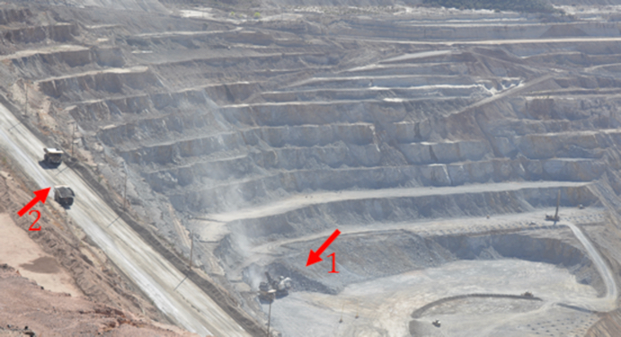
Defer stripping
As we discussed before, we would like to expedite profit making in the early years of operation, and to the extent that it is logical and achievable, we want to minimize the amount of stripping required to access the orebody. In the process of deferring stripping, we don’t want to compromise other objectives, such as the two that we just discussed.
Minimize the risk of delays in the initial cash flow
The production rate that is used for the early years of the mine is one of the more critical variables in determining the initial cash flow. Yet, it is also the variable that is subject to significant change over which you may have little control. Equipment delivery, outside contractor performance, workforce startup and training issues, and initial geologic uncertainty are examples of factors that can halve your production target in a given year. Imagine if your financial projections as supported by mine planning missed their target by 50%! Once again, you’d be looking for a new job! Consequently, the first year or two of production is de-rated to account for these uncertainties. If you were designing the mine to produce 6 million tons per year, it would not be unreasonable to choose a target for two million for the first year and three million for the second year. These aren’t arbitrarily chosen but will be based on simulations and risk analysis. The point here is that it is important to determine achievable production levels in the first few years of the mine life.
Maximize pit slope, while minimizing the risk of slope failure
We’ve looked at a few examples to illustrate the effect of the ultimate pit slope on stripping ratios and economics; and the “take-away message” is that the steeper the slope, the more favorable the economics! Unless, of course, you have slope failure! And then, once again, you are looking for a new job! Just kidding ... Even with very good ground control, slope failure can occur. It’s like walking a tight rope. The slope stability calculations are limited by geologic uncertainty, and so, safety factors are required. But how much of a safety factor: 1.5, 2.0, 4.0, or 10? There are analytical methods in rock and soil mechanics to improve the accuracy of your predictions, and the use of risk analysis is standard. Nonetheless, the possibility of a slope failure weighs on the operations and engineering personnel. A clever and necessary approach is to choose a smaller safety factor, but utilize sophisticated slope monitoring instrumentation and techniques to detect the earliest signs of incipient slope failure. Engineering and operational interventions can be initiated immediately to prevent a catastrophic loss.
Optimize cutoff grade and production rate
Mining companies perform market surveys to make an accurate estimation of the amount of product that can be sold every year, and at what price. Remember, the cutoff grade was based on an assumed selling price and an assumed mining cost. As the market changes, the cutoff grade will change, and as production costs change, for better or worse, the cutoff grade will change.
As an example, the annual tonnage that can be sold is suggested by the marketing surveys for a copper mining operation. The annual production rates for the mill and mine are calculated accordingly. Keep in mind that mill production rate only depends on ore, whereas the mine production rate includes both ore and overburden removal. The mining equipment should be selected in such a way that sufficient ore is sent to the mill, and so, there is sufficient capacity to maintain additional faces to satisfy the “sufficient exposure” constraint. There are flexibilities for both ore production and waste mining plans. Moreover, multiple destinations may be considered for the material, including sending material to a waste dump, a low-grade leach dump, a high-grade leach dump, the mill and sometimes an ore stockpile, which is used to feed the mill when mine production is down. Cutoff grades need to be determined for each of these destinations. I imagine that you are beginning to appreciate the need for thorough mine planning to support these decisions — hence, this objective to examine the economic merits of alternative production scenarios, including different ore production rates and cutoff grades, for the purpose of optimizing the cutoff grades and production rates.
Optimize method and equipment selection
Earlier in this module, the importance of selecting the proper size of mining equipment was discussed. We learned that all of the possible options for the fleet should be studied and the best option should be selected. Mining equipment selection is a complex multi-criteria decision-making problem. These parameters include, but are not limited to, the unit cost of the operation, equipment availability, selectivity, operating space, environmental impact, and many other technical and economic parameters. A mine planner should subject the proposed mining strategy, mine development plans, equipment selection, and environmental protection plans to very thorough "what if" contingency planning.
This is also a good time to remind you that mining methods and equipment can evolve and change over the life of a mine. Just because you started out with a specific method and unit operations, does not mean that you have to stick with those for the next 30 years! You may want to change one or both based on new conditions, new technology, and so on. This can only be assessed through ongoing engineering simulations and analyses.
This concludes the summary of mine planning objectives as first outlined by Mathieson. While these eight objectives are timeless in their guidance, i.e., they were true 30 years ago and will be every bit as true 30 years from today, we need to add one additional objective to reflect society’s nascent and evolving value of sustainability.
Develop sustainable mine plans to achieve sustainable mining operations
We talked about sustainability in mining and its importance. If we are to mine in a sustainable manner, then our mine planning must reflect that value. This means taking steps to avoid sterilizing the reserve, maximizing recovery rates, minimizing environmental impact, and ensuring worker safety and health through the design of the mine, the selection of equipment, and the choice of unit and auxiliary operations. Much, but not all of the mining industry has been the vanguard of the triple-bottom line: economic, safe, and environmentally responsible operations. The triple bottom line concept has evolved and changed into the term sustainable operations. It will be your responsibility through mine planning to ensure that the industry continues its journey to sustainable mining in all commodities and in all locations.
Now, armed with an understanding of mine planning, let’s take a look at surface mining methods!
Lesson 7.2: Mechanical Surface Mining Methods - Introduction & Open Pit Mining
Lesson 7.2: Mechanical Surface Mining Methods - Introduction & Open Pit Mining
Earlier in the course, we discussed the factors that go into the selection of a mining method, and we listed the major mining methods. Why can’t we use a single method to extract all minerals located near the surface?
Consider the following examples:
- A flat-lying bituminous coal seam of relatively uniform thickness. The coal is soft and the overburden can range from soft to moderately hard.
- A steeply pitching anthracite coal seam of relatively uniform thickness. The coal is moderately soft and the overburden can range from soft to moderately hard.
- A massive porphyry copper deposit shaped like a bowl or a giant mushroom. The orebody and surrounding rock are generally hard, i.e., strong and competent.
- A placer gold deposit, which consists of unconsolidated banks or layers of discrete grains, which are often found in rivers or streams.
Hopefully, thinking about these has triggered your memory of our previous lessons. The primary factors affecting the choice of a surface method are the spatial orientation of the orebody with respect to the surface, i.e., tabular or amorphous, and steeply dipping or flat-lying; geotechnical characteristics or the orebody and the surrounding materials, i.e., consolidated or unconsolidated, and strong or weak; and the topography, i.e., relatively flat, hilly, or mountainous. The size of the orebody and the production requirements may affect the choice of a method or the sub method, and as we discussed earlier in the semester, there are several secondary factors that could come into play. These will become more apparent as we look at the different methods.
Surface mining methods can be categorized into two broad groups based on the method of extraction:
- Mechanical Extraction Methods
- Aqueous Extraction Methods
Mechanical extraction methods employ mechanical processes in a relatively dry environment to mine minerals from the Earth’s crust. In contrast, aqueous methods involve water, or occasionally other liquids, to extract minerals.
The surface mining methods can be classified as shown here. We will discuss the mechanical extraction methods in this lesson.
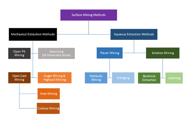
Click to expand to provide more information
Surface Mining methods can be divided into two broad categories:
- Mechanical Extraction Methods, and
- Aqueous Extraction Methods.
Aqueous Extraction Methods involve water, or occasionally other liquids, to extract minerals.
Mechanical Extraction Methods, which are discussed in this module, include:
- Open Pit Mining,
- Quarrying (of dimension stone),
- Open Cast Mining, which includes Area Mining and Contour Mining, and
- Auger Mining and Highwall Mining.
OK, with this brief “memory jogger” out of the way, let’s start our discussion of mechanical extraction methods with one of the most frequently used methods, known as open pit mining.
7.2.1: Open Pit Mining
7.2.1: Open Pit Mining
Open pit mining almost always applies to non-coal materials, mostly metal and aggregate mining. However, near-surface steeply dipping coal seams are extracted using open pit mining. Reclamation, i.e., returning the land to an acceptable standard of productive use of the open pit mine is deferred until the mine closes. Let’s look a few diagrams to better understand the relationship between the suitability of open pit mining and the spatial characteristics of the deposit.
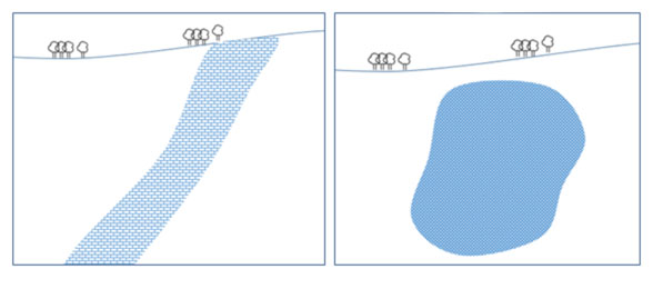
On the right side, you can see a massive deposit, and on the left, there is a steeply pitching deposit.
Now, try to imagine the way that mining should proceed to extract the ore in each case. You may think of the “open pit” as a huge upside down cone that is superimposed onto each deposit. In the case of the deposit on the right side, we would have this.
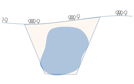
In the case of the steeply dipping deposit on the left, our open pit would look more like this.
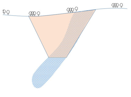
These diagrams also provide insight on the reason that reclamation has to be delayed until the end of the mine life. Simply put: we start mining from the surface and work our way, level by level, down into the deposit. If we were to return the waste material to the place where we mined it, we would block access to the ore in the lower levels.
Did you notice in the diagram of the steeply pitching deposit, the pit bottom stopped well before reaching the end of the orebody? As we go deeper, our stripping ratio will eventually become prohibitively large. Moreover, as we go deeper, mining costs, other than stripping, will increase also. For example, the time and cost to transport ore from the lower levels of the pit to the processing plant will increase to the point at which we will have to buy additional trucks to maintain production levels. When we reach the point where the cost to recover the ore exceeds its value, we have two major choices: begin the mine closure stage of the mine’s life; or begin an underground mining operation. The latter is common in metalliferous deposits. Of course, that point may not be reached for decades, as the depth of the pit may exceed 2000’ in some cases.
In the previous diagrams, I illustrated the sides of the pit with a straight line. Open pits cannot be operated in this way. Instead, the pit walls need to step down, which provides access to the pit by people and equipment, and it provides a working platform at each level. We refer to these steps as benches, and this diagram is a more accurate representation of the pit than are the previous ones.
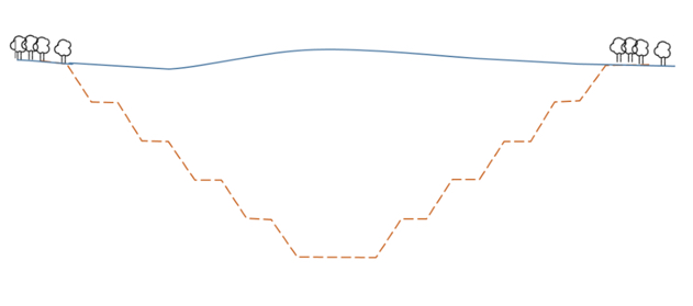
The number of benches will depend on the bench height and the ultimate pit depth. In the last lesson, the concept of slope stability was introduced, and that will weigh heavily in the decision of the number of benches, their dimensions, and the angle of the pit wall. It is incumbent on the mining engineers to ensure sure that slope instabilities will not occur throughout the mine life, as we discussed in the last lesson.
7.2.2: The World's Largest Single Pit
7.2.2: The World's Largest Single Pit
Here is an aerial view of one of the largest and most famous open pit copper mines – the Bingham Canyon Mine operated by Rio Tinto.
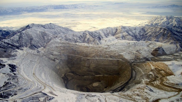
Rio Tinto Kennecott runs the world’s largest single pit, Bingham Canyon open pit copper mine. This pit stretches three-quarters of a mile deep and nearly three miles across at the top. The pit is wide enough to stack 12 aircraft careers end-to-end. This mine carries out a sequence of drilling, blasting, loading, hauling, crushing and conveying 24 hours a day, seven days a week, 52 weeks a year. It has been in production for more than a century, and has produced more than 19 million tons of copper. Gold, silver, molybdenum and sulfuric acid are byproducts of Bingham Canyon Mine. The mine has 12 shovels (10 electric, two hydraulic) that fill an average of 2,100 haul-truck loads each day. There are 110 haul trucks ranging in capacity from 240 to 320-tons. You might not expect this, but there are seven water trucks with 50,000-gallon tanks, and these trucks spray water onto haul roads round-the-clock to reduce dust. Ore is transported to, and unloaded into, one of the world’s largest crushers, running at a rate of 10,000 tons per hour. At the end of this lesson, I am going to direct you to a video where you will learn more about these large open pit mines.
7.2.3: Pit Terminology
7.2.3: Pit Terminology
Now, let’s learn the terminology associated with the pits. Using this figure, we can define key elements.
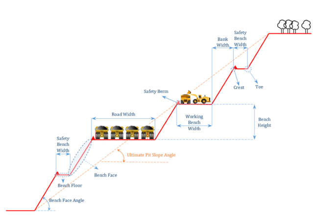
- Bench floor: Horizontal surface of the bench
- Bench face: Vertical surface of the bench
- Face angle (α): The average angle the face makes with the horizontal
- Bench height (H): Vertical distance between upper and lower bench surface
- Toe: Interior vertex formed by the intersection of the bench face and bench floor
- Crest: Exterior vertex formed by the intersection of the bench floor and bench face
- Bench width: The distance between the crest and the toe measured along the upper surface
- Bank width: The horizontal projection of the bench face
There are two types of benches in each open pit mine: working benches and safety (catch) benches.
Working Benches
Working benches are where unit operations (drilling, blasting, loading, and hauling) are performed. Working benches are wider than safety benches to provide enough room for the mining equipment to perform their tasks.
Safety (Catch) Benches
Safety benches are designed to collect the sliding material from the benches above and stop the downward progress of large rock pieces or boulders.
Bench height
Bench height is one of the first parameters to be determined during the mine design process. Can you guess the parameters that should be taken into account when determining proper bench height?
Bench height depends on several parameters:
Overburden and Ore Properties
We discussed before that ultimate pit slope depends on material (ore and waste) properties. These properties include rock strength and the number and direction of rock discontinuities. Benches are just like smaller pit walls with a much lower height (usually 20 to 50 feet). Therefore, benches should also be designed in such a way that no risk of instability is created due to excessive height of benches. There is a direct relationship between rock strength and safe values for the bench face angle and bench height.
Production Rate
Production rate of a mine is a parameter that is usually determined by market demand and selling capacity. When the required production rate is determined based on the market situation, then the annual mine production rate that includes ore and waste extraction is determined in such a way that enough product for the sale purposes is guaranteed. Higher benches are normally required to achieve higher production rates.
Degree of Selectivity
We discussed selectivity in the last lesson, and the definition of the parameter is unchanged. However, insofar as bench height is concerned, there is a selectivity issue, which is illustrated with these three figures, below. These figures (are attempting to) illustrate local variations in grade, and the effect of different bench sizes on the selectivity.
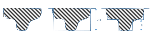
As you can see, the smaller bench height results in better selectivity. Better selectivity means less waste is mined, loaded, hauled, and run through the mineral processing plant; and this translates into lowered mining and processing costs. These mineral beneficiation plants are designed to work best when the characteristics of the feedstock into the plant lie within a specified range. If your feed into the plant is outside of the range, the plant’s efficiency will suffer. You may not recover all of the mineral, for example. Operating mines will use a blending strategy, where on a truck-by-truck basis, they will blend higher-grade and lower-grade ores to achieve a feed that is within the specified range. The more selectivity you have, the more effectively you can blend.
Size and Type of Equipment to Meet the Production Requirements
After the annual production rate of the mine is determined, the required daily and even hourly production rates will be calculated based on assumptions about the number of working days per year and the number of shifts per day. Then mining equipment is selected so that these production requirements can be met. Loading equipment is usually the first to be selected; next, appropriately sized trucks are chosen to match with the loader, and then the complete fleet of loading and hauling equipment will be specified. The maximum reach of the loading equipment should be roughly the same as the bench height.
Regulatory Limits
Federal and state regulatory agencies have regulations that limit bench height for specific mining operations, depending on the commodity, to ensure the safety of mine workers and equipment inside the pit. The engineering calculations may indicate that a greater bench height is safe, but it is unlikely that the regulatory agency would allow an exception to their rule.
Bench Face Angle
Bench face angle is ultimately limited by geotechnical considerations, as we generally want to have as steep of an angle as we can sustain without an unacceptable risk of a slope failure. Despite excellent engineering and slope monitoring, failures can occur. This photo was taken in 2013 shortly after the slope failure at the Bingham Canyon Mine. Look at the shops and warehouses in the picture to appreciate the size of this failure. It is truly a miracle that no one was killed – the potential was there for massive loss of equipment and multiple fatalities.
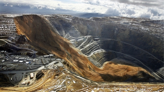
Please watch the following video (20:11). It will give you a good overview of the open pit mining method, as well as a bit more background on the slope failure. The first half of the video presents an interesting historical perspective, and the last half shows contemporary mining practices.
Safety Berm
A safety berm is a pile of broken material constructed along the crest to form a “guard rail” to prevent trucks or other equipment from inadvertently driving over the edge of the haul road. It also serves to catch falling rocks. The height of the safety berm should be greater than or equal to the tire radius of the largest truck. These berms are required by federal regulation, but even with berms, accidents can happen. The picture on the left shows a haul truck, or what remains of it, after going over the highwall; and the one on the right shows a piece of rock that slid off the highwall and landed on a truck below. The former most certainly resulted in a fatality, whereas the latter probably did not, in this instance.
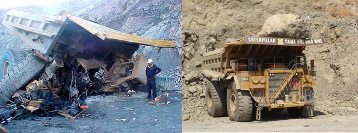
Haul Roads
These are added to the pit walls to provide access between benches and the plant next to the pit. Open pit haul roads have a gradient up to 15%. The width of the haul road is designed based on the width of the largest truck that travels in the pit and the number of the lanes that are required to provide proper access for haul trucks, auxiliary equipment such as explosives trucks and water trucks, and smaller vehicles, such as pickup trucks, while minimizing congestion.
Now, let’s review the bench geometry concepts and open pit elements by looking at two annotated photographs.
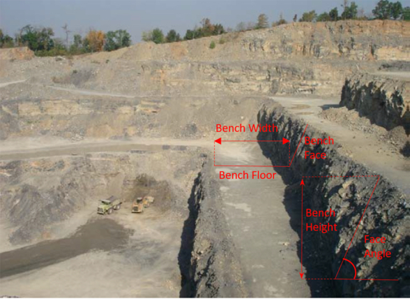
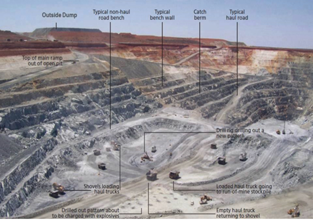
7.2.4: Mines in the U.S.
7.2.4: Mines in the U.S.
Here is a list of the largest open pit mines in the U.S.
| Mining Operation, State | Operator | Commodity | Mining Method |
|---|---|---|---|
| Nevada, NV | Newmont Mining Corp. | Gold | Open Pit and Underground |
| Morenci, AZ | Freeport-McMoRan Copper & Gold Inc. | Copper-molybdenum | Open Pit |
| Cortez, NV | Barrick Gold Corp. | Gold | Open Pit |
| Goldstrike, NV | Barrick Gold Corp. | Gold | Open Pit and Underground |
| Bagdad, AZ | Freeport-McMoRan Copper & Gold Inc. | Copper-molybdenum | Open Pit |
| Bald Mountain, NV | Barrick Gold Corp. | Gold | Open Pit |
| Safford, AZ | Freeport-McMoRan Copper & Gold Inc. | Copper-molybdenum | Open Pit |
| Mission Complex, AZ | ASARCO LLC | Copper | Open Pit |
| Sierrita, AZ | Freeport-McMoRan Copper & Gold Inc. | Copper-molybdenum | Open Pit |
| Minntac, MN | U.S. Steel Corp. | Iron ore | Open Pit |
| Chino, NM | Freeport-McMoRan Copper & Gold Inc. | Copper-molybdenum | Open Pit |
| Bingham Canyon, UT | Kennecott Utah Copper Corp. | Copper-molybdenum | Open Pit |
| Ray, AZ | ASARCO LLC | Copper | Open Pit |
| Hycroft, NV | Allied Nevada Gold Corp. | Gold | Open Pit |
| Hibbing Taconite, MN | Cliffs Natural Resources Inc. | Iron ore | Open Pit |
| Tyrone, NM | Freeport-McMoRan Copper & Gold Inc. | Copper | Open Pit |
| Tilden, MI | Cliffs Natural Resources Inc. | Iron ore | Open Pit |
| Marigold, NV | Goldcorp Inc. | Gold | Open Pit |
| Fort Knox, AK | Kinross Gold Corp. | Gold | Open Pit |
| Miami, AZ | Freeport-McMoRan Copper & Gold Inc. | Copper | Open Pit |
| Cresson, CO | AngloGold Ashanti Ltd. | Gold | Open Pit |
| Smoky Valley Common Operations, NV | Kinross Gold Corp. | Gold | Open Pit |
| Ruby Hill, NV | Barrick Gold Corp. | Gold | Open Pit |
| Keetwatic Taconite, MN | U.S. Steel Corp. | Iron ore | Open Pit |
| Mineral Park, AZ | Mercator Minerals Ltd. | Copper-molybdenum | Open Pit |
As you can see from this list, most of the US largest open pit mines in the U.S. are located in the state of Nevada and Arizona, where there are large deposits of gold and copper-molybdenum.
The sequence of steps for the development of an open pit mine is as follows:
- determining the three-dimensional distribution of mineralization and grade;
- establishing the economic limits for the pit;
- selecting suitable sites for waste embankments and soil stockpiles;
- clearing vegetation from the land intended as sites for pit and waste embankments;
- siting of processing, maintenance, office, and transport facilities close to the pit but outside potential pit limit expansion;
- selecting equipment; laying out haulage roads;
- initiating “pioneering” cuts in the form of “box cuts” or access roads.
Acquisition of rights, permitting, and construction of facilities are not shown separately in this list, but are an overall part of the development sequence.
Rio Tinto is a global mining company that owns the Kennecott Bingham Copper Mine, and they have produced an informative virtual tour (may be viewed at your own pace) of the mine and related operation. It is outstanding. You should watch it several times to reinforce the content of these lessons as well as to see vivid images of the equipment and operations in action. Follow the instructions below to get started.
- Go to the Kennecott homepage. [61]
- Scroll down until you see the Start Virtual Experience.
- You will be asked to provide your name and email address. You may do so if you choose, but if you don't want to do so, simply click the "X" in the upper right corner of the dialog box.
7.2.5: Stone for Construction, Chemical, and Other Uses
7.2.5: Stone for Construction, Chemical, and Other Uses
Before leaving this lesson on open pit mining, I want to mention an important application of this method – stone for construction, chemical, and other uses. You’ll recall from our initial discussion on mining methods that I told you that the common term for this mining is quarrying, not open pit mining. As mining engineers, that does not thrill us because quarrying is the correct term for the mining of dimension stone. However, it doesn’t much matter what we think, because millions of people use the word quarry and quarrying to refer to these open pit operations where stone is mined. Frankly, I suggest that you surrender, and refer to them as quarries as well! That’s what I am going to do here!
If you recall the graphic at the beginning of Lesson 7.1 [62] in this module on surface mining, these stone quarries account for more than a third of all mines in the U.S., numbering over 6000! The majority of the stone that is mined is crushed and used for construction – roadbed, concrete, bituminous concrete, erosion control, and so on. Limestone and sandstone are typically mined, but in some areas, an igneous rock known as trap rock is mined. These construction uses are relatively low value with the product selling for around $10 per ton. A small but important market exists for chemical grade limestone, manufactured sand, and specialty products such as kitty litter or the small grains incorporated into the surface of roof shingles. These markets will pay upwards of hundreds of dollars per ton for the mined product. Given the importance and size of the quarry industry, I wanted to make a few additional comments on this application of open pit mining.
Everything that we have discussed under the topic of open pit mining applies to quarries, i.e., open pits in which crushed stone is mined. The planning, engineering, equipment, and so on, are the same. Most quarries are smaller than the large open pit mines for recovering metals, and as such, the equipment selection may be different. Wheeled loaders are more likely to be used than shovels, and the haul truck capacity will be smaller. Hydraulic excavators may be used, but it would be rare to find a shovel. The safety, health, and environmental challenges are similar, and the engineering design and production engineering is similar. Looking at this quarry, for example, it would be difficult to distinguish it from any other open pit mine.
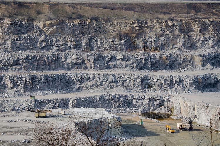
If you take MNG 441, you will learn more about the design of these open pits. Also, we offer an elective course focusing on aggregates with an emphasis on stone quarries.
Lesson 7.3: Mechanical Surface Mining Methods - Open Cast Mining & Related Methods
Lesson 7.3: Mechanical Surface Mining Methods - Open Cast Mining & Related Methods
Open Cast Mining
Open cast mining is usually associated with coal or other tabular deposits that are more or less flat-lying. A significant difference between open pit and open cast mining methods is that in open cast mining, overburden that is removed to gain access to the ore is immediately placed in the previously mined cut. Therefore, reclamation occurs concurrently with other mining activities.Two major sub-methods within open cast mining are area mining and contour mining. If the topography is relatively flat as illustrated in the left figure, then area mining is appropriate. If the terrain is hilly or mountainous as indicated by the figure on the right, then contour mining is indicated.
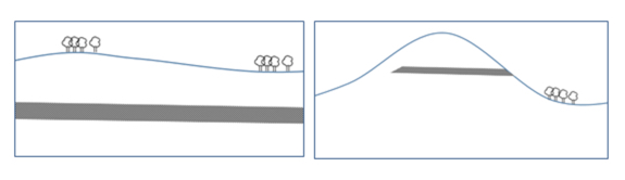
The reason that different methods need to be used depending on the terrain will become clearer as we look at them in more detail. Area mining is able to use much larger equipment, and as such will generally have lower stripping and mining costs. However, this large equipment requires a flat-lying topography to operate. Contour mining, on the other hand, is well suited to mining around the mountainsides, but uses smaller and different equipment; and, accordingly, we lose an economy of scale that we have with area mining. Nonetheless, it is an important and viable method to recover coal deposits. Let’s take a look at each sub-method in more detail.
Required Activities
Read There is no reading for this section
Complete Quiz 7 on Lessons 3, 4, and 5
7.3.1: Area Mining
7.3.1: Area Mining
In the left figure, we have relatively constant thicknesses for both overburden and ore. Our first step is to remove the surface vegetation and stockpile the topsoil for later use in reclamation. We will only remove the vegetation and topsoil in the area that we will mine within a period of weeks. Next, we need to gain our initial access to the seam, and we will do this with a box cut. Depending on the hardness and tightness of the overburden, we may need to drill and blast to facilitate its removal. If it is soft enough, we’ll remove it without the need to drill and blast. Depending on the thickness of the overburden, and the required size of the box cut, we will probably use a dragline to make the box cut, although it could be done in certain cases with dozers and scrapers. The overburden from the box cut will be placed to the side of the pit. When the coal seam under the box cut is exposed, we start mining the coal. After the coal in the box cut is removed, a subsequent cut is accomplished and the waste material from the second cut is placed in the space created by the initial box cut. This process continues by making subsequent cuts, putting extracted overburden in the former cut and mining the uncovered coal seam. The collection of sequential cuts forms a strip, and the strips will traverse a portion of the property. Take a look at this figure, and don’t be concerned about the difference between the low wall and the highwall. You can see the box cut. In the lower part of the figure, you can see the strips being mined and the overburden or spoil placed into the adjacent and previously mined strip. The overburden swells in volume when it is extracted, and that’s why you see the piles of spoil protruding above the original contour of the land.
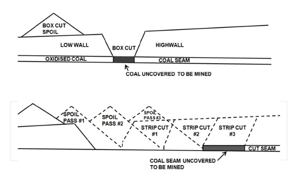
Sometimes, it is difficult to imagine the cuts and strips and how it all progresses. As you look at the pictures and diagrams in this lesson, it will come together for you. Another visual for right now would be to think of a bowling alley with its many bowling lanes. You can think of the bowling alley as the area to be mined, and each lane as a strip. Within each strip, a series of cuts will be made so that the “mining activity” can progress from the beginning to the end of the strip. Mining of the first strip is a little tricky, but once it has been completed then all of the other strips will be completed as shown in the diagram above – remove the overburden, expose the coal seam, mine the coal, cast the overburden from the next cut into the previously mine strip.
Overburden removal in US area mining is commonly accomplished with large draglines, stripping shovels, or in small mines, by conventional excavation and haulage (truck-shovel or dozer-scraper) methods. In some other countries such as Germany, bucket wheel excavators are also used to remove overburden. Dozers and scrapers are also used in clearing vegetation, removing topsoil and subsoil, establishing level benches and surfaces for the dragline, as well as many other activities that involve pushing the spoil. In the next lesson, we’ll look at a video of area mining to recover phosphate, and you will see the prep work done by the dozers as well as the operation of the dragline.
Here is a picture of a Black Thunder Mine. You can see the individual strips where overburden has been placed; and within each strip, note the individual piles. Each pile corresponds to a cut. The uncovered, but unmined coal seam is visible as well. Given the thickness of this seam, on the order of 100’, a large shovel will be used to mine it. If it were thinner, say 10’, then a small shovel could be used, but more likely a wheeled loader. Often, the coal seam is drilled and blasted to facilitate rapid loading of the coal.
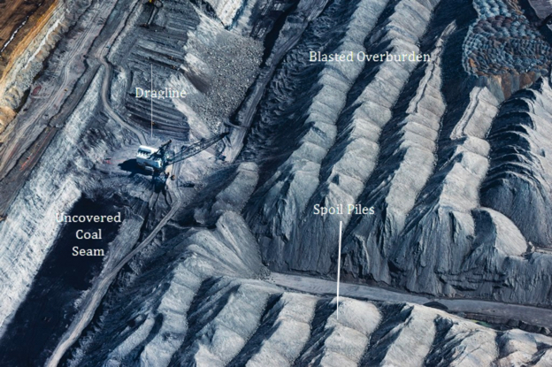
There are a few other elements within this picture that I’d like you to note. Do you see the blasted overburden, and where is the dragline sitting with respect to the top surface of the blasted overburden? Quite a bit lower, right? So, how does this happen?
A dragline has a limited reach, and there is a tradeoff between its reach and the size of the bucket. For example, it may have a reach of 200’ with a 200 yd3 bucket, and 300’ with a 120 yd3 bucket. Without getting into the design details, optimizing the reach and bucket size combination sometimes requires that the overburden be removed in two separate passes. The interesting thing about the process in the Powder River Basin is that they remove up to 40% of the overburden by a process known as cast blasting. In cast blasting, not only does the blast loosen the overburden, but the round is designed such that up to 40% of the overburden is actually thrown or cast into the adjacent strip! They may use a million pounds of ANFO or more to accomplish this!
Dozers are then used to push more of the overburden into the adjacent cut, and importantly, to create a flat and level surface for the dragline to operate. You can also see a temporary haul road developed by the dozers to provide access to the coal seam for haul trucks and to the dragline pad for smaller vehicles to service and supply the dragline.
I want to point out one last detail before leaving this picture. Did you notice the shape of the pile of overburden? They are all very distinct and nearly identical in shape. Do you think that is a coincidence? The piles of material form at an angle known as the angle of repose. This is the angle that a dry, granular, material in a very loose condition will form with respect to the horizontal. The angle of repose is a unique characteristic of the material, whether it is iron ore, coal, #2B crushed stone, flour, or sugar. If we know this angle, we can calculate all sorts of interesting things, such as the maximum angle of a conveyor belt so that the ore will not tumble back on itself or the size of a stock pile.
When it is time to reclaim the strip, bulldozers and scrapers work together to spread these spoil piles. Then the subsoil and top soil are placed back to reclaim and return the land to its original contour lines. Often, the rock layers immediately above the coal seam will be “acid bearing”, i.e., minerals such as pyrites that will create an acidic drainage when ground water percolates through those layers. Acid mine drainage is a great environmental concern, and to reduce the level of acidity under the reclaimed lands, crushed limestone is sometimes added to neutralize acid bearing layers. This process is called liming.
Here is another picture to illustrate the operations of the open cast area mining method.
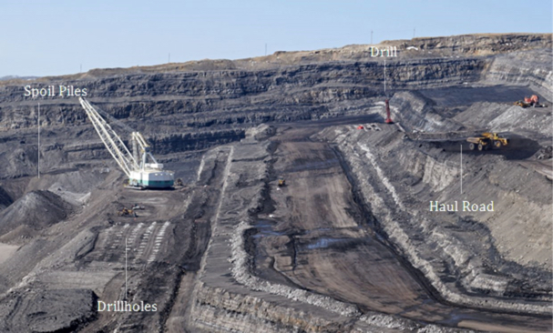
Draglines
The dragline is an important piece of mining equipment, and you will find it in a variety of, and sometimes unexpected, operations. Let’s look at the fundamental parameters that define draglines for a given application. Each dragline is defined on two parameters: bucket capacity and boom length. Bucket capacity is used to determine the hourly production rate of the equipment, while the dragline’s dumping height and digging depth depend on its boom length. Digging depth, dumping height, and operating radius are the primary parameters that should be considered in selecting appropriate bench dimensions for a particular dragline. These three primary parameters are illustrated in this diagram.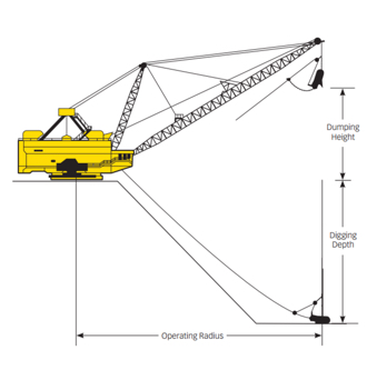
Please take a minute and think about the way that each of these three parameters plays a role in the design and the width of the strips.
Next let’s take a look at the key components of a dragline. You should understand the purpose of the drag, hoist, and dump ropes. You may want to think about the challenges of the structural design of the boom itself, and the tradeoff between bucket capacity and boom length. What about moving the dragline? How does it move about the bench? Very slowly and with great difficulty!!! There are no wheels nor crawler tracks because it is so massive and so heavy that conventional approaches would fail in all but the smallest draglines. Instead, the dragline walks! It sits on a giant cast iron tub so that its enormous weight can be distributed over a large area. On either side of the tub, there is a massive shoe. The shoe is connected to an eccentric cam, and to move, the shoes lift the tub off the bench and propel it forward where it comes to rest. And then, the cycle is repeated. Fortunately, the dragline does not need to move quickly in the course of normal production. However, if you need to move the dragline some distance, say to an adjacent property located on the other side of a highway, it can be a tedious process – like watching grass grow!
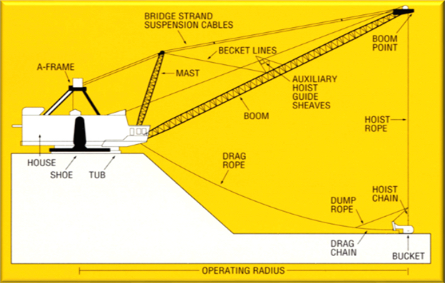
Now, let’s look at the operating cycle of the dragline in more detail, with the help of these diagrams.
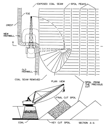
The dragline is positioned on top of the blasted material, which has been leveled and prepared by a dozer. The drag bucket is positioned at its furthest reach, lying on the overburden. The drag rope will begin to pull the bucket towards the tub, and as the drag bucket is pulled, it will dig into the material and the bucket will be filled. Once filled, the dragline operator will begin to hoist the bucket and will begin to swing the boom toward the spoil pile. By the time the bucket reaches the spoil pile, the operator will have completed hoisting the bucket, and will then dump the bucket. Once dumped, the operator will swing back to the position to dig, while at the same time, dropping the drag bucket so that when the swing cycle has been completed, the drag bucket will be lying in position to begin the cycle all over again. A typical time to complete one cycle is 45 seconds.
Bucket Wheel Excavators (BWEs)
Let’s close out this discussion on area mining with a brief mention of bucket wheel excavators (BWE), shown in the picture here. BWEs are massive machines to quickly remove overburden. To gain an appreciation for their size, look for the front-end loader in the lower left part of the picture. Did you find it? These machines have been used successfully in the brown coal fields of Germany for many decades. Some BWEs were imported into the U.S nearly 50 years ago. Unfortunately, the results were disappointing. The characteristics of the overburden were unsuited to the capabilities of BWEs. The bucket wheel excavator is best used for soft and loose overburdens. While these were common in the German lignite fields, they were less common here in the U.S. Consequently, they were never adopted for use in the U.S.
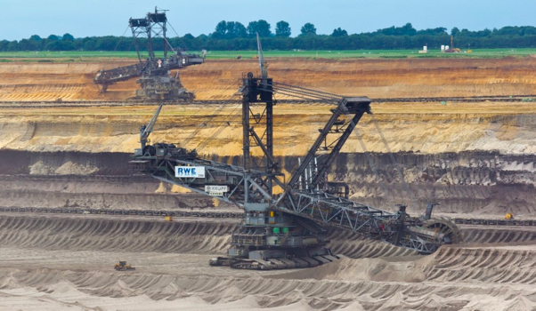
7.3.2: Contour Mining
7.3.2: Contour Mining
It would be great if all coal were found in conditions similar to those in the Powder River Basin: relatively flat and wide-open space, thick coal seams, and shallow cover (overburden). Mother Nature was not so accommodating! A lot of high quality thermal and metallurgical coal is found in rugged terrain, in areas such as the Appalachian Coal Field, which runs from Pennsylvania down to Alabama. Contour mining methods evolved to allow the economic extraction of coal using smaller and more agile equipment with more flexible mining patterns.
As with area mining, it is necessary to remove the vegetation and remove the overburden to gain access to the coal seam. There are two ways to handle the removed overburden: haul it all the way down the hill and put it into a chosen valley in horizontal layers; or to place it in the void of the cut, where the coal has been already removed. Mining will proceed by advancing into the hillside until reaching the break-even stripping ratio. At this point, the highwall will remain. Under certain conditions, we may choose to take advantage of the exposed coal seam, and develop an underground mine or practice highwall mining, which will be discussed later in this lesson.
Now, let’s take a look at a schematic view of contour mining approach and then a photo of a contour mining site. The diagram shows more than one coal seam. In fact, it is not uncommon for multiple seams to be recovered. It creates a small sequencing and scheduling challenge because you have to remove the interburden between the seams, and place it, but it is commonly done.
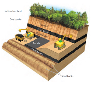
Note the highwall in the photo, and the exposed coal seam.
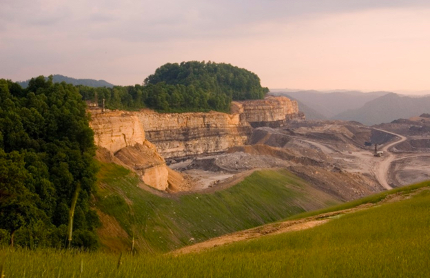
Haulback Mining
An important submethod within contour mining is haulback mining. Haulback mining, which is illustrated nicely in this diagram from the textbook, is a method in which overburden removal and then coal extraction follows the outcrop, proceeding in a series of nearly rectangular pits. As mining is advancing at one end of the rectangular cut, reclamation is occurring on the back end. In this method, mining roughly follows the contours of the land, and the ultimate pit width is dictated by the economic stripping ratio and steepness of topography.
Haulback mining starts with developing a box cut and hauling the overburden to a suitable disposal site. Coal is mined out and mining progresses with removing the next cut of overburden, and hauling it by truck, scraper, or conveyor to fill previously mined-out cut. This method is called haulback mining, because waste moves in a direction opposite to the direction of mining, as illustrated in the diagram.
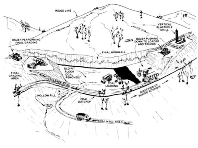
Mountaintop Removal
Mountaintop removal is another submethod of contour mining where a flat lying coal seam occurs near a mountain top and outcrops on opposite sides of a hill. When the overburden is sufficiently thin (less than 165 feet) across the hill, the deposit can be mined from outcrop to outcrop. In this method the hill is completely removed and the spoil is leveled rather than contoured to approximate the original topography, creating a flat land. This method was commonly used in Appalachia, but is very controversial, and is no longer recommended. The below picture shows a mountaintop removal operation in southern WV, prior to reclamation of the site.
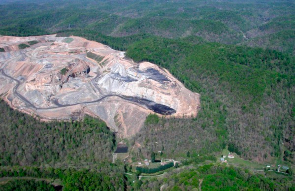
7.3.3: Auger Mining
7.3.3: Auger Mining
Earlier in this lesson, you saw the highwall that remains after the ultimate pit limit is reached in a contour mining operation. At that time, I pointed out the possibility of recovering the coal under the highwall, by either developing an underground mine or highwall mining. The former is rarely economically feasible today, but the latter is commonly practiced. A distinction is made between auger mining and highwall mining, and this will become clear shortly.
In auger mining, auger holes are bored horizontally into the coal seam from the last contour cut at the high wall. As the auger rotates and advances forward, coal is cut and pushed out of the hole by the rotating action of the auger. The action is similar to that of a carpenter boring a large hole in wood using an auger bit, and that is where the name derives. Auger mining recovers around one-third of the coal under the highwall, for whatever depth of penetration is achieved. Auger cutting heads can be as large as 7 feet in diameter and may be drilled to a depth of more than 300 feet. An auger mining machine is shown here.
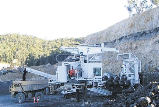
A highwall, showing the auger holes is shown in this picture:
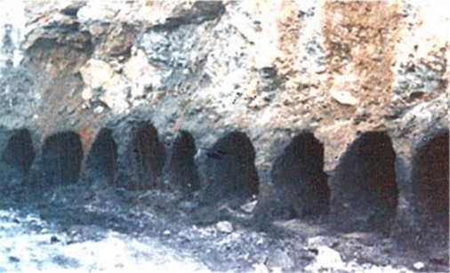
When the ultimate pit limit is reached, it is difficult to “pack up and leave” when you see the exposed coal seam. So, in some regard, the company looks at this secondary recovery technique, i.e., auger mining, as the “icing on the cake.” It amounts to coal recovery at a very low cost. It is, however, somewhat problematic and controversial. The low recovery, less than 35%, means that the majority of the reserve remains in place, but it has been sterilized, i.e., left in a condition where it will be essentially impossible for anyone to recover the remainder in the future. The holes into the side of the hill create drainage holes for acid-laden water, and that is a big problem. Surface subsidence and spontaneous combustion in the auger holes are additional concerns.
7.3.4: Highwall Mining
7.3.4: Highwall Mining
Highwall mining is very similar to auger mining in its concept, where the entry into the coal seam in made at the highwall of the ultimate pit limit. The difference lies in the use of a more sophisticated machine, known as a highwall miner. The highwall miner shares some common elements with a continuous mining machine. It has bit-laced cutting drum, and the coal is fed back through a materials handling system to the bench by the highwall, where it is loaded out. That’s where the similarity stops.
The highwall miner is equipped with sophisticated monitoring and a remote control system. It is important to maintain accurate control of the cutting head so that it remains in the coal seam, rather than drifting up or down into the adjacent rock layers, and so that a constant rib thickness is maintained between holes. Unlike the continuous miner, where a shuttle car is waiting at the tail to load out the coal, the highwall miner needs to move the coal from the cutting head to outside the highwall. Essentially, there is flexible conveyor train following the cutting head. There is a significant amount of support equipment required outside of the hole, adjacent to the highwall, to provide power and handle the cables and hoses. The computerized supervisory control system and operator station are located within the highwall miner’s structure that is located adjacent to the highwall. This picture with the artist’s cutaway shows a highwall mining machine.
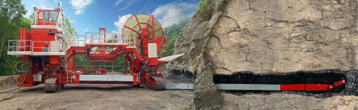
What do you gain with the added complexity and cost of a highwall miner over an auger? The highwall miner can advance 1200’ under the highwall compared to a typical 300’ for an auger. Recovery rates improve from roughly 30% for an auger to near 50% for a highwall miner. The highwall miner can adapt more easily to varying seam thickness or other changes under the highwall. Its production rate can be much higher than an auger, and, in general, the unit cost of coal mined with the highwall miner will be less than with an auger. The risk of worker injuries is less with a highwall miner, primarily because the likelihood of a cave-in is less than with an auger; and attempting to remove an auger from a caved hole is fraught with dangers. On the negative side, the highwall miner does not reduce the concern over acid mine drainage.
Here is a photo of the highwall showing the holes created by the highwall miner.
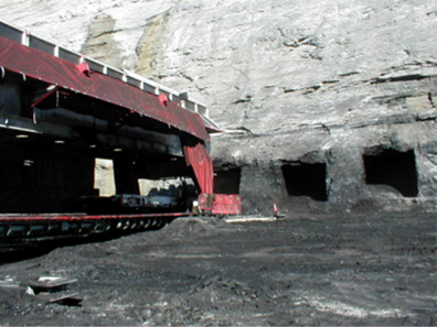
Lesson 7.4: Aqueous Extraction Methods
Lesson 7.4: Aqueous Extraction Methods
We’ve examined surface mining from a very general perspective, and we’ve studied the class of mechanical surface mining methods. The other major class of surface mining methods is aqueous extraction. Aqueous extraction is distinguished from mechanical extraction by one characteristic: all of the aqueous methods depend on the use of water or another liquid to extract the ore, and often the water is used to aid in the gravity separation of the valuable mineral. We’ll look at three methods within this class of mining methods: Dredging, Hydraulic mining, and solution mining. These methods are important to the recovery of certain commodities, but their overall application is limited compared to mechanical extraction methods. Here in this lesson, we’ll simply introduce the basic concepts, and leave further study to advanced courses on surface mining.
7.4.1: Dredging or Dredge Mining
7.4.1: Dredging or Dredge Mining
A dredge is the principal piece of equipment used in the dredging method and, essentially, a dredge is a boat containing specialized mining and materials handling components. Accordingly, a dredge requires a body of water in which to operate. In many cases, this is a natural body of water such as a river or a lake, but in others, it is a manmade pond or small lake. Of course, the only reason for floating a dredge is to recover something of value at the bottom of this body of water. We need to add one more condition, and that is: the material of value on the bottom must be unconsolidated, such as sand and gravel, or it must be very soft. Simplistically, the dredge is designed to lift these materials of interest from the bottom up into the dredge. Shortly, we will look at how the payload is moved in a little more detail, but for now, let’s talk for a moment about the kinds of materials that are typically recovered with this method, dredging or dredge mining.
The bottom of rivers, lakes, and harbors is often a good source of gravel. Gravel can be used sometimes in concrete as well as for a variety of other purposes such as architectural and landscaping purposes. Dredging to remove this material has the additional benefit of deepening the channel or harbor, and sometimes that is the primary purpose of dredging, and the recovery of minerals is a secondary benefit… the “icing on the cake,” so to speak!
Glaciers once covered a significant portion of the Earth’s surface, and the movement of these glaciers created extensive unconsolidated deposits of materials containing not only sand and gravel, but gold, tin, diamonds, and other heavy minerals. These alluvial deposits created by glaciation, are also known as placers. I mention this here because you will sometimes hear or read about placer mining or alluvial mining. Although these terms may be used interchangeably with dredging or dredge mining, you can’t assume that to be true in all cases. As we will see, hydraulic mining may be used in these deposits as well. Regardless, if we have a body of water covering a placer deposit, we will consider strongly using dredge to recover the minerals of interest.
Moreover, if we have such a deposit that is not underwater, but is in an area that could be easily flooded, we will consider making our own lake and then using a dredge to recover the bottom materials. If the deposit is in an area with a very shallow water table, we may simply have to remove several feet of overburden, e.g., vegetation and soil, and the excavated area will fill with water on its own. Then, we can float the dredge and mine the deposit. There are other circumstances where we could create a manmade lake to mine the deposit, but it a complicated process, because we cannot take any action that could have an adverse environmental impact.
Let’s talk a bit more about the dredge itself. A dredge is defined by the way in which it recovers the ore from the bottom. The four types are bucket-wheel, ladder, clamshell, and suction. The choice will depend on the depth of the deposit below the surface of the water and the degree of consolidation of the deposit. The size of the dredge will depend on the desired production rate and the characteristics of the body of water, e.g., depth and extent. Let’s start by looking at a picture of a dredge.
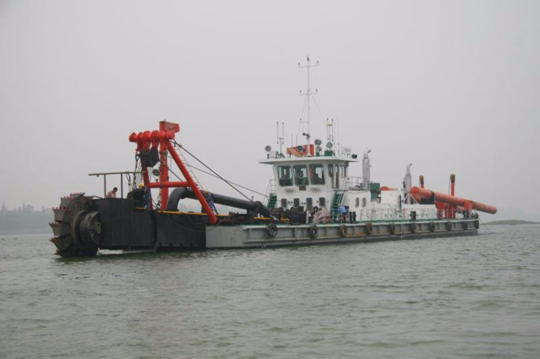
This is a large dredge, and specifically, it is a bucket-wheel dredge. You can see the bucket wheel on the left side of the picture. The bucket wheel rotates, digging into the soft material at the bottom. The dug or “mined’ material is then transfer onto the dredge. Typically, some sort of a gravity separation is employed to segregate the material of interest from the silt, mud, and other detritus of no interest. The latter is then immediately returned to the water.
The bucket-ladder dredge is probably the most common type of dredge, as it is the most flexible method for dredging under varying conditions. The excavation equipment consists of an endless chain of open buckets that travel around a truss or “ladder.” The lower end of the ladder rests on the mine face—that is, the bottom of the water where excavation takes place—and the top end is located near the center of the dredge. The chain of buckets passes around the upper end of the ladder at a drive sprocket and loops downward to an idler sprocket at the bottom. The filled buckets, supported by rollers, are pulled up the ladder and dump their load into a hopper that feeds the separation plant on the dredge. After the valuable material has been removed, the waste is dumped off the back end of the dredge. Here is a picture of a bucket-ladder dredge, which gives a clear front view of the bucket ladder.
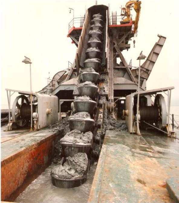
Here is a view of a bucket-ladder dredge used to mine phosphate.
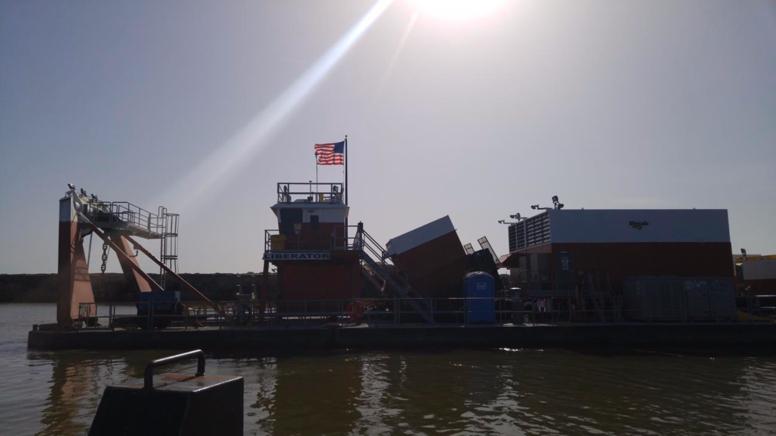
And here is that same dredge in a photo taken from a distance.
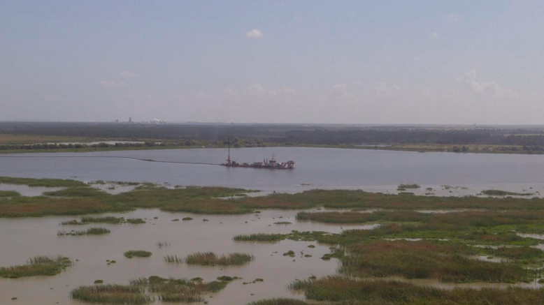
Finally, here a view from the operator's cab of that dredge. Notice the computer displays providing not only video images of different parts of the dredge but also sensor data that the operator can use to better control the operation of the dredge.
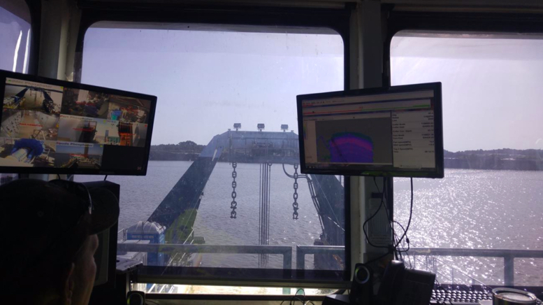
The clamshell dredge, unlike the previous two, employs a batch rather than continuous process. This type of dredge utilizes a clamshell bucket that is dropped to the bottom, scoops a bucket of material, and is hoisted back to the dredge where the bucket is dumped. This dredge can operate in deeper water than other systems and handles large material, e.g., larger rocks, well. A typical cycle time would be on the order of one minute, depending on the depth of the water. You understand the drawback of batch or discontinuous systems, and consequently, this style of dredge would only be used when its unique strengths are necessary. A typical clamshell dredge is shown here. Note the ability of this style dredge to place its payload on the dredge or on a nearby barge or structure.
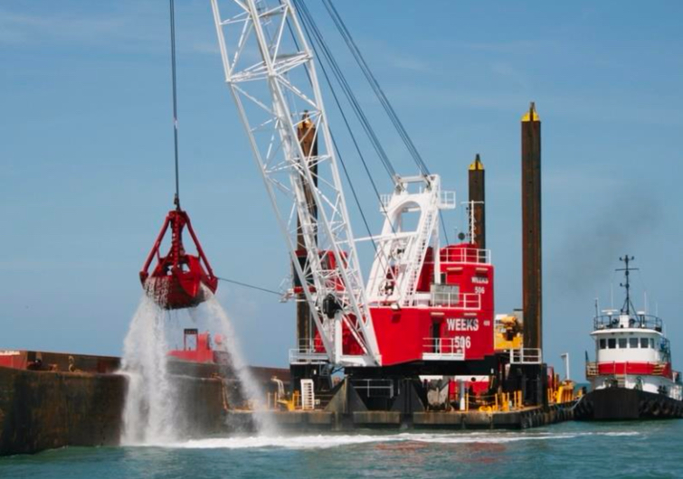
The fourth type of dredge is a hydraulic dredge. Imagine a big vacuum cleaner with a long hose – the hose is dropped to the bottom, the “vacuum” is turned on, and the material is literally sucked up the hose and captured on the dredge. Basic physics limits the amount of “lift” that can be achieved. However, the amount of lift can be supplemented with a high-pressure spray around the suction nozzle – essentially a push-pull system. This is known as hydrojet assistance. This style of dredge is suited to digging relatively small-sized and loose material such as sand and gravel, marine shell deposits, mill tailings, and unconsolidated overburden. Hydraulic dredging has also been applied to the mining of deposits containing diamonds, tin, tungsten, niobium-tantalum, titanium, and monazite. This figure diagrammatically illustrates the use of a suction dredge. Note that the use of a hydraulic pipeline to move material off the dredge is often associated with the use of this type of dredge.
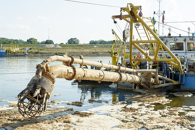
This picture shows a very small suction dredge, which might be used to clear a tailings pond, for example.
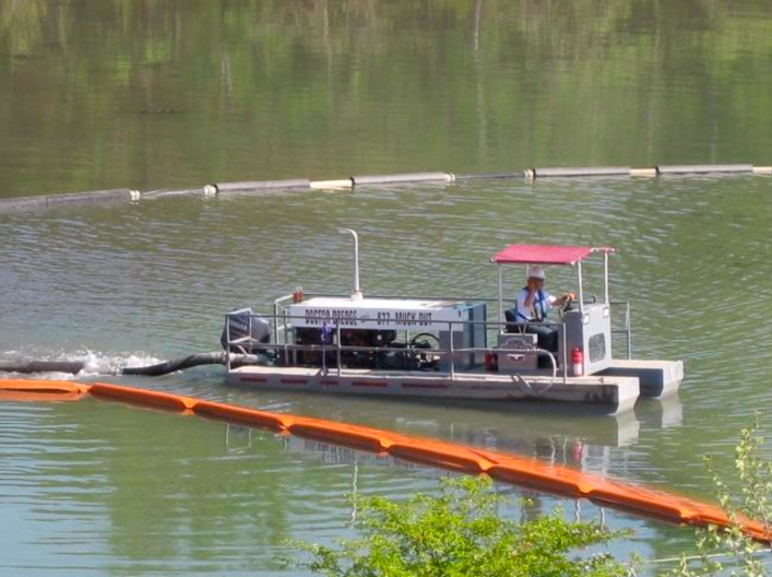
7.4.2: Hydraulicking or Hydraulic Mining
7.4.2: Hydraulicking or Hydraulic Mining
Hydraulic mining uses high-pressure water cannons, known as monitors, to dislodge relatively unconsolidated material. One of the earliest applications of hydraulic mining was to break down banks of alluvium containing gold and silver. These alluvial deposits are firm, but break down quickly upon the application of the water cannons. Of course, if digging the banks of alluvium were the goal, we could use wheeled front loaders or other traditional digging and loading equipment. The goal is not only to excavate the banks but to separate the gold, silver, or other metals from the sediments in these alluvial deposits. Toward that end, we use a gravity separation with water in a device known as a sluice. The sluice which is usually constructed, consists of a trough on a slight incline. The trough bottom may have embedded ridges. The idea is that the material laden water will flow gently down the sluice and denser materials will settle to the bottom. Toward this end, the material loosened by the water cannon is channeled to the sluice; and as it passes through the sluice, the heavier materials, e.g., grains of gold and silver, settle on the bottom of the sluice while the water and sediment are carried away.
Another important, but limited, application of hydraulicking is to break down mineral ores prior to slurry transport. Slurry transport is an important materials handling method in which a water-solid mixture is pumped over some distance. In some cases, the slurry may be pumped for 20 or 30 miles, while in others, it may be hundreds of feet. One such application is in phosphate mining. The overburden is removed, typically with a dragline, and then a monitor is used to break down the phosphate matrix into a slurry, which is then pumped to the mineral processing plant. We’re going to examine a case study in the next Lesson, and at that mine, they use a dragline to excavate the phosphate matrix and place it into a small pit where it is broken down and fed into the slurry pipeline. You’ll see some good pictures of hydraulic monitors in that case study.
7.4.3: Solution Mining
7.4.3: Solution Mining
Solution mining is the extraction of the ore through a dissolution process, i.e., we pump a solvent through the ore, the solvent dissolves the constituent of interest, and then we recover and process the resulting liquid, which is known as the solute or pregnant liquor. We can apply this method to in-situ deposits using a borehole mining method, or to mined material using a heap leaching method. In-situ, which implies “in-place” “in-the-seam”, and using an in-situ method, means that we extract, i.e., dissolve, the material of interest within the deposit and leave behind the gangue or waste minerals. In-situ recovery has the advantage of not disturbing the surface with a mining activity and of eliminating surface piles of processing plant tailings or waste. It has the disadvantage in some applications of creating a potentially hazardous environmental situation if the solvent or solute can migrate into the environment. Let’s talk about the in-situ methods first.
7.4.4: Borehole Mining Method
7.4.4: Borehole Mining Method
One hole is drilled into the deposit for the purpose of pumping the solvent into the deposit, and one is drilled at some distance from the other to recover the solute. The solvent flows between the two holes creating a cavern where the ore was dissolved. For some minerals such as common salt (NaCl) or trona, water is the solvent. For other minerals, a chemical solvent is required. Interestingly, sometimes these caverns are of greater value than the extracted mineral! In the Louisiana salt domes, for example, the caverns are used to store crude oil and natural gas. Often, multiple holes are drilled within the area of interest. Occasionally, only one hole is drilled, but the borehole is divided into an inner and outer annulus so that the solvent is forced down one, and the solute is retrieved through the other. This is the case for the Frasch process for recovering sulfur. The Frasch sulfur process uses steam to melt and dissolve the sulfur in the water, which is then forced back up the borehole; or, in other cases, the melted sulfur is allow to drain and collected in subterranean pools where it is then pumped to the surface.
7.4.5: Heap Leaching Method
7.4.5: Heap Leaching Method
Heap leaching was first used to extract very low grades of metal ore from piles of plant tailings or waste rock. In the case of copper, for example, a solution of sulfuric acid was released at the top of the pile and allowed to percolate down through the pile. The effluent was collected and washed over scrap tin. The copper would precipitate out on the tin, the tin would then be smelted, and the copper would be separated from the tin. All-in-all, it was a fairly clever and economic process to extract metal from material that otherwise would have been discarded as waste. Unfortunately, there was no thought given to the consequences of the effluent seeping into the ground, and in the end, this practice resulted in massive pollution around the mine site. The old Anaconda Copper Company mine in Butte, Montana, for example became an EPA Superfund Site! Today, heap leaching is practiced, but with proper engineering controls in place to ensure that it proceeds with no damage to the environment. Among other precautions, extensive containment barriers are constructed with multiple levels of redundancy.
Today low-grade ores are “mined” on the surface and placed on these containment pads so that the valuable metal can be leached out of these “heaps.” This is an important method for recovering gold from low-grade ore that could not be economically processed by any other means. The mining of the low-grade ore is usually by large dozers, front loaders, and trucks. Usually, the depth of the excavation is quite limited, and two of the reasons for this are that as the deposit depth increases, the grade may improve to allow economic exploitation by another mining method; and the cost of excavating this low-grade ore increases with the depth, and quickly it becomes uneconomic. The time required for the leaching to be completed can vary from weeks to years, with the latter being more common; and during this period, bacterial action, as from metal oxidizing bacteria for example, is critical to the success of the process. A variation of heap leaching involves constructing the “heap” in a dump, and calling it dump leaching. Large containment vessels are being used on a limited basis as well.
Both heap leaching and borehole mining have become the favored exploitation methods for recovering uranium. This figure illustrates a heap leaching operation.
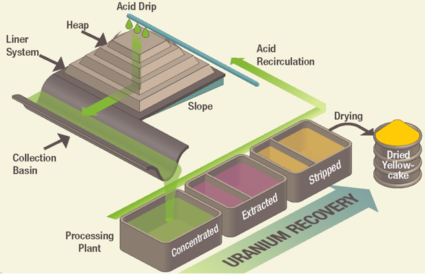
This figure illustrates the process at Uranerz’s Nichols Ranch Mine. This is a good example of how a borehole mining method is employed for in-situ recovery of a mineral.
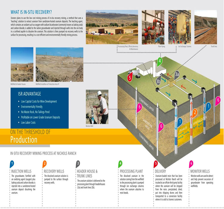
Lesson 7.5: Case Study - Phosphate Surface Mine
Lesson 7.5: Case Study - Phosphate Surface Mine
We’re going to take a close look at one mine in this lesson – a surface mine in Florida, from which phosphate is obtained. This mine utilizes an open cast method to expose and extract the phosphate ore, or phosphate matrix as it is known; and then they use hydraulicking to breakdown the matrix. The resulting slurry is then transported several miles in a slurry pipeline to a mineral processing plant.
I’ve got some good pictures and videos that will help you to better understand the material that we’ve been covering in this module on surface mining. I don’t intend to ask you a lot of specific questions about this phosphate mine, but, hopefully, this case study will help you to better answer questions about mine planning and the mining methods in general.
We’ll start out by learning a few facts about the phosphate industry, and then we’ll quickly move into the details of this mine’s operation. I also want to acknowledge Mosiac for allowing me to tour their mines and work with their staff, and for providing many of the photos and videos in this lesson. Mosaic is a world leader, not only in the mining of Phosphate, but in their approach to sustainable mining. They hire a high proportion of engineers to work at their mines and processing facilities, and they run a first-class internship program for mining and other engineers.
7.5.1: Overview of the Phosphate Industry
7.5.1: Overview of the Phosphate Industry
Phosphate is a key component in agriculture (food production)
- granular mono ammonium and diammonium phosphate pellets for fertilizer
- animal feed supplements
- elemental phosphorous for food-additive applications.
A limited amount of elemental phosphorus is used in other industrial applications.
In 2015, Phosphate rock was mined by 5 companies at 11 mines:
- in 4 states
- 80% in Florida and North Carolina & 20% in Idaho and Utah
- to produce 27 million tons of marketable product with a value of $2.4 billion fob mine
World Mine Production and Reserves (USGS Minerals Commodity Survey)
| Country | Mine Production, 2013 | Mine Production, 2014 | Reserves |
|---|---|---|---|
| United States | 31,200 | 27,100 | 1,100,000 |
| Algeria | 1500 | 1500 | 2,200,000 |
| Australia | 2600 | 2600 | 1,030,000 |
| Brazil | 6000 | 6750 | 270,000 |
| Canada | 400 | --- | 76,000 |
| China | 108,000 | 100,000 | 3,700,000 |
| Egypt | 6500 | 6000 | 715,000 |
| India | 1270 | 2100 | 35,000 |
| Iraq | 250 | 250 | 430,000 |
| Israel | 3500 | 3600 | 130,000 |
| Jordan | 5400 | 6000 | 1,300,000 |
| Kazakhstan | 1600 | 1600 | 260,000 |
| Mexico | 1760 | 1700 | 30,000 |
| Morocco and Western Sahara | 26,400 | 30,000 | 50,000,000 |
| Peru | 2580 | 2600 | 820,000 |
| Russia | 10,000 | 10,000 | 1,300,000 |
| Saudi Arabia | 3000 | 3000 | 211,000 |
| Senegal | 800 | 700 | 50,000 |
| South Africa | 2300 | 2200 | 1,500,000 |
| Syria | 500 | 1000 | 1,800,000 |
| Togo | 1,1110 | 1200 | 30,000 |
| Tunisia | 3500 | 5000 | 100,000 |
| Vietnam | 2370 | 2400 | 30,000 |
| Other Countries | 2580 | 2600 | 300,000 |
| World Total (rounded) | 225,000 | 220,000 | 67,000,000 |
There are three sources of Phosphate Rock
- Sedimentary deposits of marine origin
- Africa, China, Middle East, and United States
- Igneous and metamorphic deposits
- Brazil, Canada, Finland, Russia, and South Africa
- Biogenic deposits from bird guano
High-quality sedimentary phosphate deposits are mined in the U.S.
The mined phosphate rock is beneficiated by a process in which the phosphate rock is reacted with sulfuric acid to produce an intermediate feedstock of phosphoric acid.
Gangue minerals associated with the deposit impact the cost of processing the ore
Clays and silica are the only significant gangue minerals in these high-quality deposits Carbonates are present in significant amounts in lower-quality depositsThe gangue minerals can require larger quantities of reactants (sulfuric acid), which significantly increases production costs, and can increase time require for downstream processing, e.g., filtration; and they can interfere with the ore recovery and concentration in downstream operations, e.g., float processes.
Carbonates are more problematic. Dolomite, for example, shares mineralogical similarities with phosphate, and this makes it more challenging and expensive to remove it.
- Major gangue minerals of primary interest in U.S. operations:
- dolomite, calcite, silica, and clays
- Certain other gangue components may need to be removed during or after the production of the phosphoric acid:
- cadmium, radium, uranium
- Clay slimes are removed in log washers or hydrocyclones.
- Silica is removed using the well-established Crago double float process.
7.5.2: MOSAIC Florida Phosphate Operations
7.5.2: MOSAIC Florida Phosphate Operations
I suggest that you go to Mosaic’s website [85] to learn more about the company. Doing so, you will arrive at this "Who We Are" page, and you will note that Mosaic is not only a major producer of phosphate but also of potash!

Their Florida operations are located in five counties of southwest Florida, as shown on this map. This is a rural area of Florida.

Resource
The phosphate rock deposit consists of a matrix of phosphate pebbles, clays, and sand, along with other gangue such as silica. (Carbonates occur in increasing amounts in the lower quality deposits.)
Key Characteristics
- The matrix is relatively unconsolidated and is typically on the order of 10’ thick.
- It is covered by an average overburden thickness of 30’ ranging from 15’ to 50’.
- The overburden is unconsolidated sand and organic matter.
- The matrix is underlain by a hard limestone.
- The water table is near the surface throughout the region.
Given these key characteristics, you should be able to choose the mining method. Can you do so? Well, at the beginning of the lesson, I told you that they employed the open cast method. Nonetheless, I would hope that you could come to that conclusion on your own. The use of hydraulicking on the other hand, would not be apparent to you.
Let me tell you the overall sequence of operations to remove any mystery!
- Prepare the site for mining
- dozers
- Install utilities
- electric power
- water drainage
- “Pitsrdquo; for breaking down the matrix with monitors
- slurry pumps and pipelines
- Remove overburden
- dragline
- Mine the ore
- dragline
- Prepare for the ore for hydraulic transport to the plant
- hydraulic monitoring to break-up matrix
- Backfill the cut
- dragline
- Reclaim the site
- sand tailings pumped to the site
- level spoil piles and grade
- dozers
- loaders
- hydraulic excavators
- add top layers
- revegetate
We’ll take a look at many of these in more detail; but now, let’s start with an aerial view of the mine.
7.5.3: Welcome to the Operation
7.5.3: Welcome to the Operation
This picture was taken by a Penn State mining engineering intern while riding in the company helicopter!
The features in this photo will become known to you as we continue.
Best Management Practices (BMP) features and land development
Off to the left side of the photo, you see a waterway that looks like a nicely manicured stream or small river. It is manmade, and it is done to control the water table around the mine and ensure that the water table outside of the mine’s perimeter is not lowered or otherwise harmed. At these mines, this “ditch” is known as a best management practice ditch, because it is part of their stormwater pollution prevention plan (SWPPP) required under the Clean Water Act, and is considered a “best practice” to accomplish the intended goal.
The construction of the BMPs precedes other development activities. Once completed, roadways are constructed into the site, vegetation is cleared, and the top soil layers are carefully placed away from the active site for use during reclamation. Then, the site will be graded and leveled to provide a working surface for the draglines.
7.5.4: Infrastucture Installation
7.5.4: Infrastructure Installation
Once a level site has been prepared, the work of placing utilities will begin. In this photo, they are placing high voltage cable (yellow in color), which will supply power for the dragline as well as the many pumps used on the site.
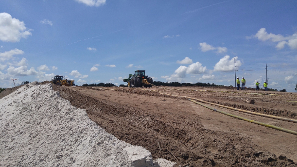
As work on the electrical power infrastructure is continuing, a series of dewatering holes will be developed. This photo shows the electrical infrastructure, and do note the overhead electrical lines in the background and the electrical installation in the foreground. If you look closely, you can see 6” diameter PVC pipes protruding at the surface of the ground. These are dewatering holes.
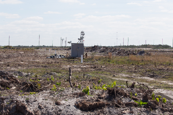
This next photo gives us a close-up view, and we can see other important features. There is a small pump at the bottom of this hole, and you can see the small discharge line, where the pumped water enters a larger diameter collection pipe that is serving the entire row of dewatering holes. You can also see the electrical cable that goes down the hole to the pump at the bottom. These holes go to the bottom of the matrix, and so, a typical hole would be 50 – 60’ deep. Those pretty pink flags that you see are markers so that equipment, such as tractors and pickup trucks, don’t accidentally run over and damage pipes or electrical cables.
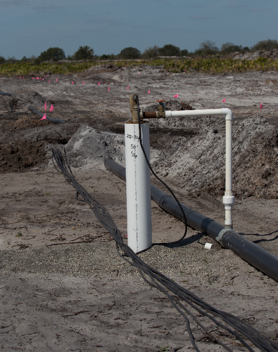
This next picture focuses on an electrical installation. As is often the case, this equipment is mounted on a skid so that it can be attached by a wire rope to a dozer and pulled to a new location. This equipment provides the hardware to allow a connection to overhead power lines, if required, a transformer to step the voltage down to a level required by the machines and pumps, and protective devices to allow switching and implementation of other safety features.
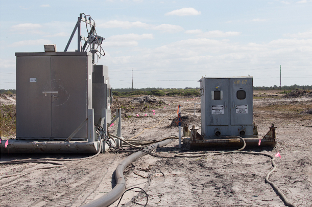
7.5.5: Overburden Removal
7.5.5: Overburden Removal
With the utilities in place, we are ready to install the pits and monitors and to begin overburden removal. Let’s talk first about overburden removal. A typical dragline in use at the Mosaic mines in Florida is shown in the next picture. Remember, we talked about how draglines move – they walk. Look at the two big walking shoes on this dragline, one on each side. The shoe is green and there is a yellow guardrail around the top surface of the shoe. As you might imagine, these things don’t break any land speed records!

Here is another aerial view of the mine, but in this one, you can clearly see the dragline at work.

Here is a close-up of the dragline removing overburden. If you look to left, you can see the last strip or cut that was mined (it is now filled with water).
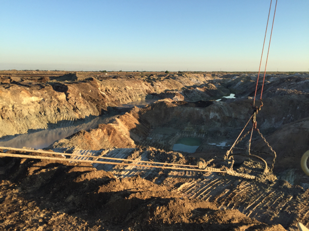
This short video clip (2:11) will give you a feel for the overburden removal cycle. Note the development activities ongoing to the left of the active cut.
In this video clip, you probably saw the greenish colored material at the bottom. That is the phosphate matrix, and in this next picture, you can see it as well.
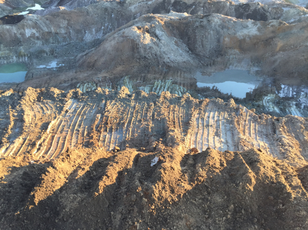
Evaluating the Phosphate Matrix
You’ll recall from our discussion of mine planning, that mineral processing plants are designed to perform best when the feed into the plant has characteristics that lie within a fairly narrow range. When the mined material is outside of this range, the practice is to blend loads of material from different mining faces to achieve the desired feed to the plant. This is true in phosphate mining as well. How do you know the qualities of the ore being mined at a given location on a given day? You send in the geologists to take samples and visually inspect the ore. In this next picture, you can see the geologist, accompanied by operations personnel, preparing to sample the phosphate matrix in the drag bucket.
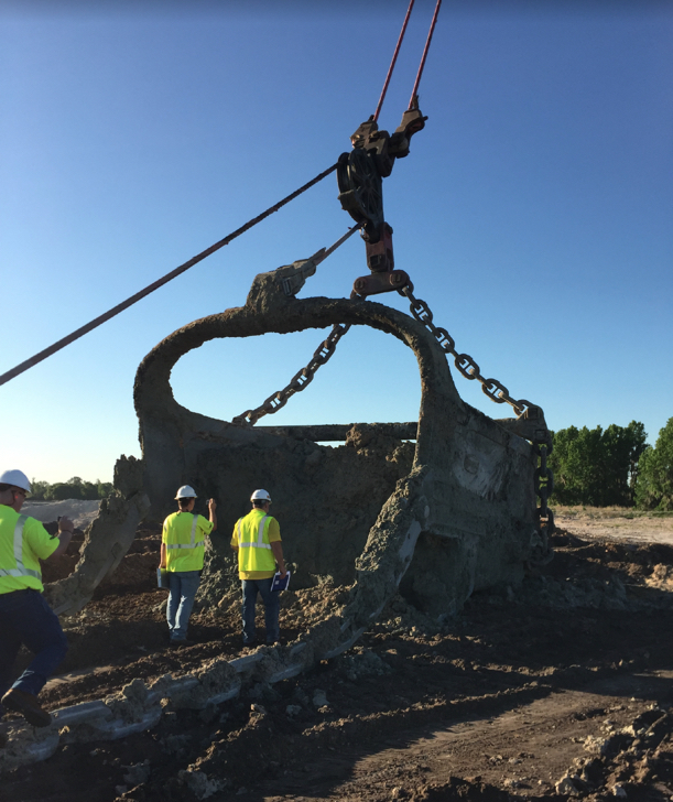
Now that we have a clearer understanding of this phase of the operation, let’s look at the dimensions of a typical strip or cut.
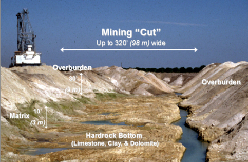
7.5.6: The Mining Operation
7.5.6: The Mining Operation
Before the dragline can begin to mine the ore, the hydraulic monitors must be set up and ready to go. That work will be occurring while the dragline is removing overburden. Let’s start out by looking at a completed installation which is in operation. In the following video clip (0:35), you will see the dragline dumping the phosphate matrix into a constructed “pit.” There, the monitor blasts the matrix into fine particles. The slurry pours out of the pit, through the iron grate that is designed to keep large chunks from passing, and into a sump where the slurry is drawn into the pump and transported into the slurry pipeline that goes back to the plant. The video clip is 35 seconds in length, but actually represents about 10 minutes of actual work. In other words, you are seeing it in fast motion!
7.5.7: A Closer Look
7.5.7: A Closer Look
Let’s look at this construction in more detail. Looking at the next picture, we have a hole that has been dug, and they call it a “pit.” The pit is bisected by the steel grate, which they refer to as the “pit trap.” To the left of the grate, we have the hydraulic monitor, and this is where the dragline deposits the phosphate matrix. On the right side of the grate, we have the slurry intake pipe. In this photo, the intake has been lifted above the water line. Normally, the intake is submerged below the water line.
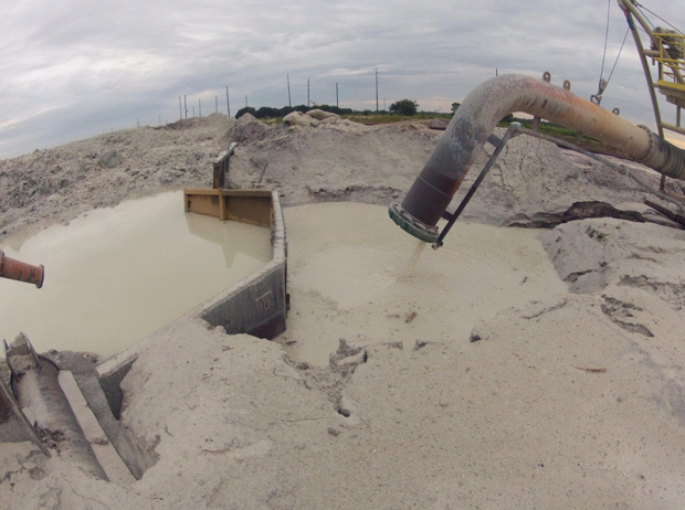
In this next photo, we can see more clearly the construction of the pit and pit trap.
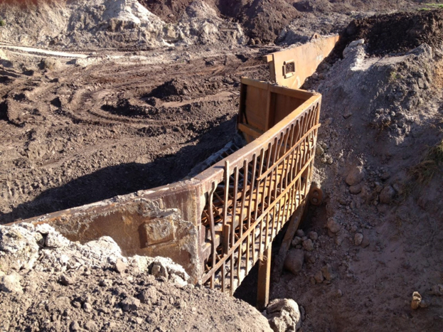
The next step in the construction of the pit is to install the monitor. Small dozers are used to construct the pit and to do the grading around it. In this next photo, look to the right of the worker. Do you see the specially outfitted tractor with the winch/crane assembly? This is what they use to move and position the monitors, pit traps, pumps, and related assemblies.
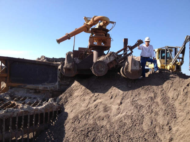
The next picture provides a wide-angle view of the pit and related equipment.
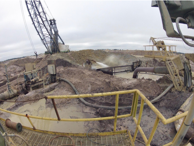
7.5.8: Construction of a New Pit
7.5.8: Construction of a New Pit
Now, with this understanding of the individual components, let’s watch a video (8:57) showing the construction and set up of a new pit. Note all of the related activities in the background.
Of course, as mining advances, it becomes necessary to move the pit to the next location. This is a process accomplished over a shift. The next video, which is about 6 minutes in length, captures a complete move over a nine-hour period. Fasten your seatbelts!
The design of a slurry transport system is covered in our materials handling course, MNG 404. Here, it is worth noting a few defining characteristics of the system used at the Mosaic mines.
- 2000 tph capacity
- 1500 hp or greater pump motors
- up to 62” diameter pump impellers
- pipelines up to 10 mi long
- 20” diameter pipe
- pumps every 1 mi
- slurry
- 35% solids by weight w/ up to 6” – 8“ size fraction
Finally, we can take a look at the placement of overburden into a previously mined cut.
7.5.9: Reclamation
7.5.9: Reclamation
Reclamation is the final part of the sequence of operations, and as you know, it is an ongoing activity. Mosaic does a stellar job of reclaiming the land, and given the growing conditions in Florida, within months after mining has been completed, the area appears undisturbed and back to its original appearance. Actually, that is not always true – often the reclaimed area is suitable for a higher purpose than the overgrown scrub areas that preceded mining. On their website, they discuss the reclamation activities in more detail.

With that, our case study and the module on surface mining comes to an end!
Module 8: Underground Mine Development
Module 8 Overview
Module 8 Overview
Fewer than 10% of the mines in the United States are underground mines. Given a choice, we’d always choose to mine by a surface mining method, as surface mining is less expensive than underground. Unfortunately, we don’t usually have a choice! Certain commodities are found predominantly deep beneath the Earth’s surface – too deep to consider surface mining; and notable examples include gold, lead, molybdenum, platinum, potash, trona, salt, silver, and zinc. Other commodities are commonly mined on the surface, but because of their value, they are deep mined as well; and notable examples include diamonds, metallurgical & thermal coal and copper. In recent years, a third reason for going underground has emerged: the commodity is located in a suburban or urban environment, and local zoning ordinances preclude a surface mining operation. We are seeing this primarily with limestone. Finally, as time passes, the reserves that are easiest to exploit have been mined. Increasingly, we are having to mine deeper and deeper, and under more adverse conditions. The following article from the Wall Street Journal illustrates this well: "Mining a Mile Down: 175 Degrees, 600 Gallons of Water a Minute. [86]" Can you imagine mining under such conditions? It is a great engineering challenge, and we will see more and more of this!
The development of an underground mine follows a similar process to initial stages of surface mine development. A site has to be prepared, office buildings, shops, warehouses, and mineral processing facilities need to be constructed. And as with surface mine development, the timing of the infrastructure will minimize any premature upfront cash expenditures. The significant difference between surface and underground development is access to the orebody. This is usually easy to accomplish in surface mining because the orebody is close to the surface and often it is only necessary to remove vegetation, the soil layers, and a modest amount of overburden. By contrast, accessing a deep orebody can take considerable time, effort, and money. In many cases, we can access and begin mining a surface deposit within weeks, whereas it might take several months of even a year or more to access a deep deposit.
Learning Outcomes
At the successful completion of this module, you should be able to:
- demonstrate knowledge of the four types of openings used to access an ore body for underground mining, and specifically:
- when each would be selected, i.e., the pros and cons,
- where they would be located, and
- the materials handling options for each type of opening after the mine is in production;
- demonstrate knowledge of the process / unit operations for developing shafts, slopes, drifts, and box cuts, including the type of equipment used;
- define, and/or draw & label as appropriate, the basic terms used to describe underground mining methods and activities - specifically, the common deposit and spatial, directional, and excavation terms (see text pp 79-83 for listing and definitions);
- sketch a generalized underground metal mine, for the purpose of illustrating the basic infrastructure of such a mine;
- name the three classes of underground mining methods, and describe the distinguishing characteristic of each class;
- demonstrate an understanding of the conditions under which one method would be selected over another. Describe the “defining” or “distinguishing” characteristics of each method;
- describe and sketch the essential elements of three major unsupported methods: room and pillar, a.k.a. stope and pillar, shrinkage stoping, and sublevel stoping. Name some commodities mined by these methods;
- draw a typical room and pillar coal mine layout showing mains, submains, and panel entries;
- describe the sequence of development and production for each method; identify typical equipment utilized for the associated unit operations; additionally:
- for the room and pillar method, describe conventional, continuous, and longwall mining,
- for shrinkage stoping, describe the more popular variant known as VCR,
- for sublevel stoping, describe the variant known as bighole stoping;
- describe and sketch the essential elements of the major supported method known as cut and fill. Explain what is meant by drift and fill, undercut and fill, and overhand cut and fill;
- describe the sequence of development and production for the cut and fill method; identify typical equipment utilized for the unit operations and auxiliary operations;
- explain the concept of the historical methods of square-set stoping and stull stoping, and in what very limited circumstances they might be applied today. Describe how cut and fill mining can be used in conjunction with another primary mining method to increase the extraction ratio;
- describe and sketch the essential elements of the major caving methods known as sublevel caving and block caving, as well as another important caving method known as longwall mining (for coal and noncoal).
Lesson 8.1: Orebody Access
Lesson 8.1: Orebody Access
There are three common methods to access an orebody under deep cover. They are shafts, declines, and adits/drifts.
Shafts
A shaft is a vertical or nearly vertical opening driven from the surface to the deposit. The cross-section of a shaft is usually elliptical or circular, as these shapes are stronger than square or rectangular openings, provide less resistance to airflow, and maximize the useful space per dollar spent on the shaft. The diameter or dimensions of the opening are based on the purpose for which the shaft will be used, and the diameter can commonly range from around 6’ to 30’, and sizes outside of this range occur occasionally. The shaft may be used solely to hoist ore to the surface, provide ventilation, or to transport people and supplies. Commonly, shafts are partitioned and serve more than one purpose.
Declines
A decline can take the form of a slope, which is a straight opening driven at an angle, or a ramp, which is similar to a slope except that it is generally helical in shape. The angle of the slope, as well as the design radius and the angle of the ramp, depend on their intended use. The dimensions of a decline will depend on the purpose for which it is to be used. A slope may be outfitted with a belt conveyor to move ore out of the mine, or perhaps there will be track for rail haulage. The slope may be partitioned with a top and bottom compartment to facilitate multiple uses, including ventilation. A ramp, on the other hand, is used primarily for access, to move people, supplies, and ore between levels or to the surface, and it will be sized to accommodate the largest piece of equipment in use. The ramp may also be used for ventilation and utilities, e.g., electric power cables and water lines.
Adits/Drifts
Openings that are driven within the ore and follow the seam or vein are known as adits when they are driven in metalliferous veins or drifts when driven in coal and nonmetal seams. Functionally, there is little difference between a slope and a drift or adit. It’s simply that one, the slope, is driven in the country rock, i.e., the nonmineral-bearing rock around the ore, whereas the other, the adit or drift, is driven in the ore. In the past, it was common to find veins or seams that intersected the surface. The practice, as you would expect, was to begin mining the ore where it intersected the surface, and then to follow the vein or seam and continue mining. In some cases, this led under a mountain, in other cases, with a vein or seam that was dipping at some angle, the driven opening could go quite deep. Regardless, the opening at the surface, or the entry point into the mine, is known as an adit or drift. Thus, when you hear the term slope, you will know how that differs from drift or adit. To be honest with you, I find some of these definitions and the subtle differences among them to be a bit tedious. But, they are in common use, and you should know what they mean, and you should use the correct term.
And number 4: the Box Cut
There is a fourth means of access that is used infrequently, but is common enough to warrant its own category. It is known as a box cut. You may recall learning this term earlier, as this term is taken from surface mining, and specifically the open cast mining method known as area mining. In that method, an initial cut is made to start the process, and the material from this cut is hauled away. Typically, this cut looks like a box: it is few hundred feet wide and several hundred feet in length, and may be up to a few hundred feet in depth. However, the dimensions are specific to the application. You’ll find this method of access being used in coal and limestone, and often the depth of the box is less than 100’. The idea is to have the floor of the box at the same level as the seam. This allows openings to be driven into the seam. And what would these openings be called? Yes, drifts. Of course, roadways need to be constructed to allow equipment, supplies, and personnel to be transported down into the box cut, and into the mine. Sometimes, the box will be enlarged to allow placement of buildings, crushers, and so on within the box cut.
Here is a photo of a box cut to access a coal seam. You can see the overburden that was removed and carefully place in the background. Note the overburden layers and the rock overlying the coal seam. In the front left side of the picture is an access road into the box, although it is difficult to see clearly.
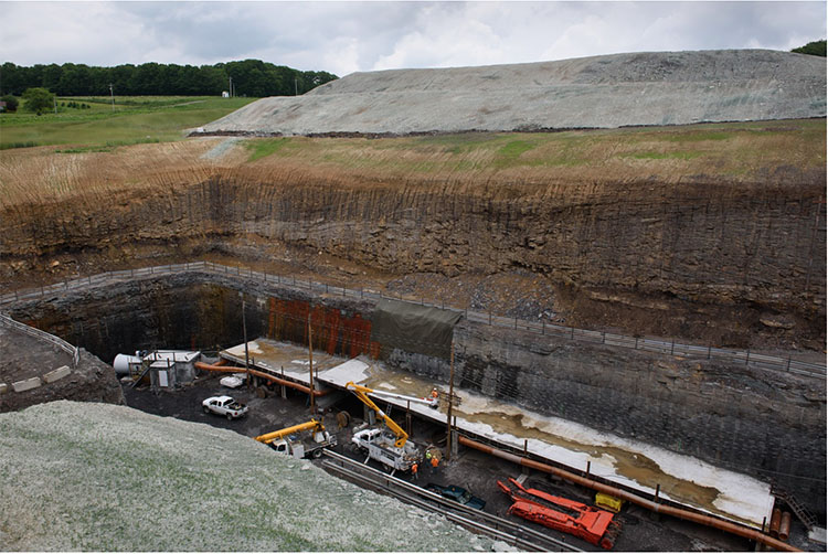
The choice of an access method is generally limited. The following list illustrates the factors that go into the selection.
- If the seam or vein intersects the surface, a drift or adit will be the choice.
- If the seam is close to the surface, i.e., typically within a few hundred feet, a box cut will receive serious consideration.
- The construction cost of a shaft is about three times the cost of a slope; however, the construction footage of a slope is generally at least three times that of a shaft.
- The deeper the orebody, the more likely that a shaft will be used.
- Transporting large equipment into a mine is more easily accomplished with a slope rather than a shaft. Large equipment must be cut into pieces and reassembled underground if there is no slope access.
- Construction of a slope is more challenging in difficult ground conditions, and could sway the decision to choose a shaft.
- A shaft limits the materials handling to batch operations, which is a serious limitation, as discussed earlier in the semester.
- Quite a bit of real estate is required to put in a slope, and a ramp can be constructed under a much smaller surface footprint.
- A ramp precludes continuous haulage, which can be a disadvantage.
- Coal mines require two means of access, and it is common for deep mines to use both a slope and a shaft. This allows them to realize the benefits of both means of access.
This is not an exhaustive list of considerations, but it is representative. As you progress in your studies and learn more about ground control, ventilation, and materials handling, the decision criteria will become even clearer to you. These openings must serve as primary conduits for ventilating air – either fresh air intakes or exhaust air returns, and that will impact the size and configuration of the choice. The material handling options, which center around batch versus continuous, will be important factors in the decision, as well as the need to move very large equipment on a regular basis. You’ll recall from our discussion of auxiliary operations that we have several materials handling options. These can be summarized here by access type.
| Shaft | Slope/Drift/Adit | Ramp | Box Cut |
|---|---|---|---|
| Hoist | Rail | Rubber-tired haulage | Rail |
| Vertical belt | Belt | Belt | |
| Elevator | Inclined hoist | Rubber-tired haulage | |
| Rubber-tired haulage |
Placement of the Access Opening
What about the placement of the access opening on the property? All things being equal, you’d probably want the access to be near the centroid of the orebody. The location of roads and rail service to your property could affect the decision, as could topography. You wouldn’t want your shaft to be located at the lowest natural drainage point of your property, and permitting constraints limit the placement as well. In general, you cannot place an access opening down dip from the seam that you are mining because any water accumulation in the mine would then drain out of the mine. That can be an environmental issue that you have to address. Ground conditions may affect your placement decision as well. Unless there are overriding circumstances, logistical considerations will weigh heavily in your decision of where to locate the shaft, slope, ramp, or box cut.
8.1.1: Construction of the Access
8.1.1: Construction of the Access
We should talk a little bit about the construction of these means of access. The construction of the drifts, adits, slopes, and ramps does not differ significantly from the unit and auxiliary operations for mining the ore, which we discussed previously. However, these access openings are generally, except to remain serviceable for the life of the mine, unlike many of the other workings that are in use only while the ore in that part of the mine is being exploited. Consequently, extraordinary measures can be justified to ensure the stability of these openings over many years. What are these measures? Reinforced concrete liners, steel arches, and/or additional rock and cable bolts to ensure long-term stability. Some rock types deteriorate when exposed to moisture, and you may shotcrete these surfaces to prevent oxidation and deterioration.
Shaft sinking, on the other hand, may involve some operations and equipment that we didn’t address directly in our study of unit and auxiliary operation. Shaft sinking can be accomplished with a conventional cycle, i.e., drill-blast-muck-hoist, or a continuous cycle using a blind-shaft boring machine. Let’s talk about each cycle.
Previously, we talked about the conventional cycle used in mining as consisting of the unit operations: drill-blast-load-haul. The same unit operations are used to sink a shaft, but the name for loading has changed to mucking and the name for hauling has changed to hoisting. As we sink a shaft into the earth, we cannot load the blasted material with a wheeled loader for example and haul the blasted material off to a dump… obviously! Instead, we use a clamshell mucker to grasp the broken rock and drop it into a large hoist bucket. When the bucket is full, it is hoisted to the top of the shaft and dumped into a waiting truck, where it will be hauled to a dump pile. Hence, the name change for loading to mucking and hauling to hoisting in the conventional cycle for sinking a shaft. It should be noted that the word muck refers to any broken, i.e., blasted, rock, and the word mucking is an old mining term for the operation of loading out muck. Here is a video illustrating the mucking and loading operations in a shaft. This example is for a fairly shallow and small shaft. Larger and deeper shafts involve more complex arrangements, consisting of multiple deck stages and equipment. Nonetheless, this video (2:28) illustrates the basic concept.
During the sinking of the shaft, the auxiliary operation of ground control is generally crucial. The first tens or even a hundred or more feet are driven in relatively poor quality material, e.g., soils and weathered materials that will not stand on their own. In other words, they would tend to fall into the shaft. In areas of past glaciation, the overburden may consist of a hundred feet or more of loosely consolidated rubble. In these areas, the only way to sink a shaft is to freeze the overburden, drill and blast through the frozen material, and then immediately place a liner in the shaft to support the shaft walls. Glaciers made it as far south as Illinois, for example, and so, if you want to sink a shaft down to a coal deposit in the Illinois basin, chances are good that you will have to freeze the alluvial till, i.e., the unconsolidated overburden. Freezing is accomplished by drilling and placing refrigerant pipes around the location of the future shaft, setting up a large refrigeration system, and pumping coolant through the pipes until the ground is frozen. Then, the shaft sinking can begin. Here is a good video (4:37) to illustrate a shaft sinking process in which freezing the overburden is part of the project.
The ground support to maintain the integrity of the shaft walls may consist of rock bolts and wire mesh, but will normally require the use of liners. The liners could be timber, which was used in the past, mortared brick liners, which are also a thing of the past, or most common, concrete liners. In most cases, the concrete liners, a foot or more in thickness, are poured in place. Sometimes, precast liner segments are delivered to the site and set into place, and then a grout is pumped behind the liner to fill the space between the rock wall and the liner. The liners will change over the depth of the shaft depending on the need. If there is a problem with ground water infiltration, steps will be taken to seal the shaft in the water-bearing horizons. This is not as simple as it may seem. At depth, the hydrostatic pressure on that water could reach 500 to 1000 psi or more! To withstand these forces, specially constructed steel liners are used. They may be made out of steel that is ½ to 1” thick, and then welded into place with a concrete ground pumped behind the liner to fill the void between it and the shaft wall. Here’s a picture of such a liner in the shop prior to delivery.
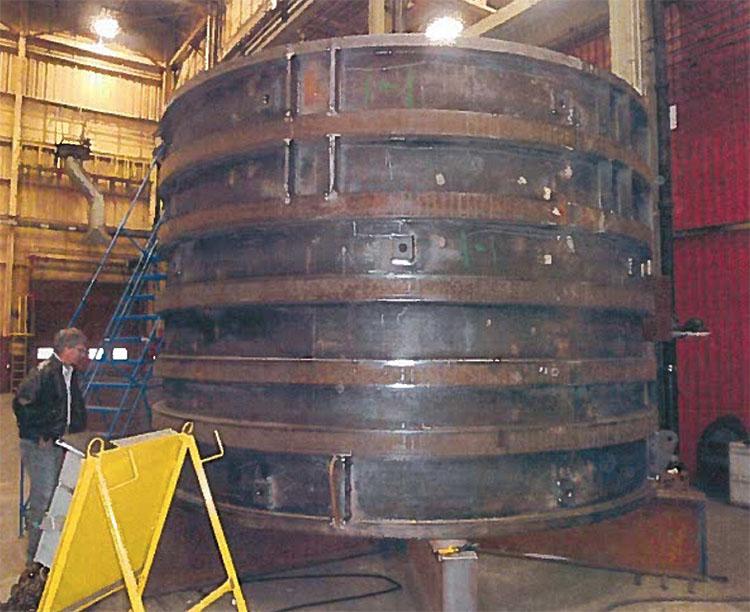
And here is a picture on site. You can see the liners waiting to be installed, along with the gantry for lowering them into the shaft. In this case, they are being set in the first 900’ of the shaft.
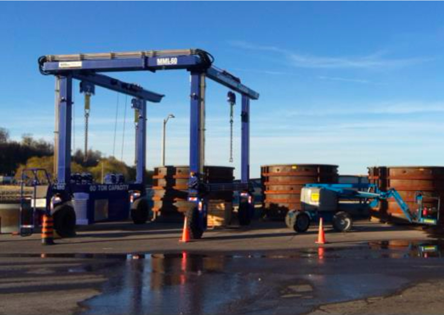
8.1.2: Revisiting "The Quest for Continuous"
8.1.2: Revisiting "The Quest for Continuous"
In a previous lesson on “the quest for continuous,” we looked at the motivation for replacing conventional cycles and the equipment for doing so. In the case of shaft sinking, the same principles have been applied. A variety of boring machines has been developed, and consist of a rotating and bit-laced head, a built-in materials handling system to clear the cut material and send it on its way to the surface, and the means for advancing, guiding, and controlling the borer. Likely, there are stages immediately above the borer that are outfitted to allow placement of liners. The following video clip (10:35) provides a detailed look into the functionality of a modern shaft boring machine.
In soft to medium harness rock, the boring machine is the preferred choice, as it can be done faster and at a lower cost than with conventional methods. However, in hard materials, a conventional drill and blast cycle is the only viable choice. This is similar to what we find for continuous mining methods in various deposits. There is one other machine of note for smaller diameter shafts – the raising boring machine.
Small diameter shafts, say less than 10’ in diameter, are required in many applications. They are used for emergency escape hoists, ventilation shafts, and travel ways between levels in a mine. The latter are known as raises, and this is where the name, raise borer, originated. In the good old days, raises and small diameter shafts were driven using conventional cycles. Today, a continuous cycle is used in most cases.
Raise boring requires that the bottom of the raise terminates in an existing mined opening. The first step in using a raise borer is to drill a pilot hole down to the exiting opening. Once completed, a large diameter cutting head is threaded onto a drill steel that connects to a power source on the surface or the upper level. The power source, i.e., the raise borer, provides thrust and rotation for the cutting bits. The cuttings fall to the lower level where they must be loaded and hauled. Take a look at this figure – it makes more sense if you can see it!
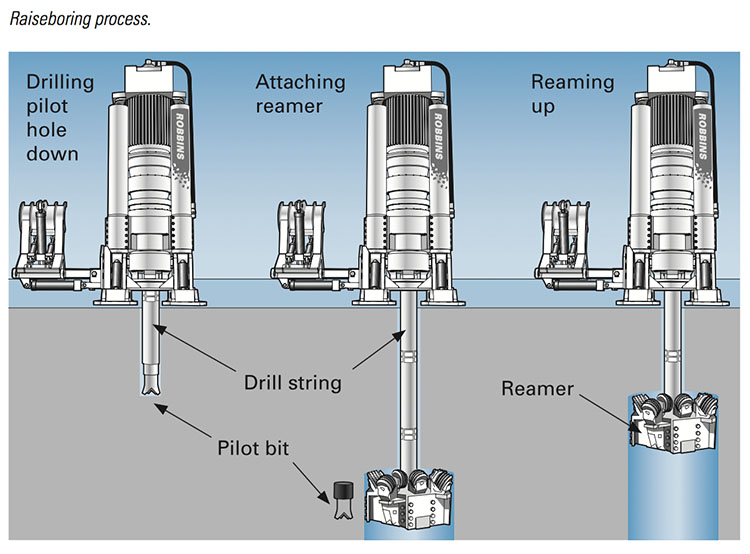
Here is a picture of the power unit. Raise borers can excavate an inclined open as well as vertical, and they can bore upward, although that is done with less frequency.
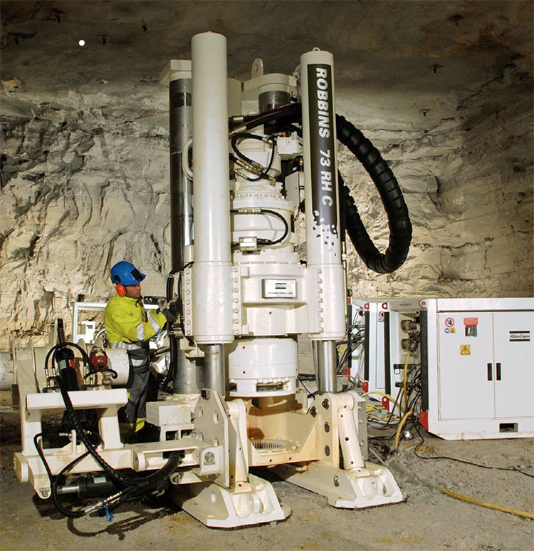
8.1.3: Odds and Ends
8.1.3: Odds and Ends
There are a few odds and ends – points that need to be made, but which I haven’t discussed until now. I’ll finish out this lesson by covered these.
The shaft collar is the name given to the point where the shaft intersects the surface, and it is also a structural component of the shaft. It is typically reinforced concrete and it will be either anchored into bedrock or tied into a liner that is anchored in the bedrock. The collar serves an important structural function for equipment associated with the shaft, and it is used to limit surface drainage into the shaft.
A building or structure is associated with the shaft. If there is a hoist, there will be a headframe. Hoists are always used to haul ore up the shaft and out of the mine. The hoist may also include a cage. This is a steel structure, typically with open steel mesh construction giving it the name “cage” used to transport miners and supplies. The trip to the bottom or back up to the top is known as a mantrip. In deep mines, the cage will likely have multiple floors so that a hundred or more miners can be transported at one time. When it takes 15 to 30 minutes to make the descent, you want to minimize the number of trips! Hoists are of two general types: drum or Koepe (friction hoist). You will learn how to design both in MNG 404, and we won’t go into the differences here, although they are discussed in the text. If there is no need for a hoist, i.e., to transport ore, but only a need to transport people and supplies, then an elevator would normally be used. The elevator is similar in construction to one that you would find in a high-rise office building of 100 stories.
Here is a cross-section of a shaft showing the compartmentalization or multi-function layout. Half the shaft is dedicated to hoisting ore, and there is a skip at the bottom and a skip at the top of the shaft. As one skip is being unloaded at the top, the other is being loaded at the bottom. For reasons that will become clearer later on, this is a Koepe hoist. The other half of the shaft is dedicated to a cage. This cage is connected to a drum hoist. You might want to think about why the Koepe hoist is used in the one case and the drum hoist in the other.
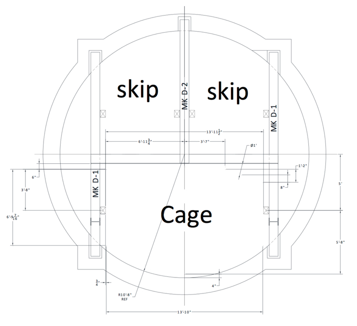
Shaft development practices have changed over the last few decades, with bored shafts being much more common and the "circular" shaft becoming all but universal for large shafts in new mines. In coal mining, about half of all shafts are now sunk by blind-boring methods. It has become common for main shafts up to 16’ to be drilled in this fashion. In addition, many coal mining companies now use bleeder shafts to simplify their longwall ventilation systems. These are sometimes drilled using blind-boring rigs. Raise-bored shafts are done as well, but access must be available underground to make this feasible, and the need for a mucking and transportation system underground makes this alternative less favorable. For large shafts, greater than 20’, in coal mines and for most metal and nonmetal mine shafts, conventional shaft-sinking methods are still commonly used.
We’ve talked little about slopes and ramps because their construction differs little from the conventional mining cycle. However, it should be noted that tunnel-boring machines are being used with increasing frequency to drive large slopes of considerable length. The cost of bringing a tunnel boring machine to a site, and setting it up is very high, and can only be justified for large diameter slopes that are greater than a few thousand feet.
The slopes used in today's coal mines are normally driven with two compartments: an upper compartment to accommodate a belt conveyor and a lower compartment containing track that is normally used for personnel and supply transport. The two compartments are separated by a horizontal concrete divider and are supported by bolts, wire mesh, or steel arches. Slopes in coal mines are often horseshoe-shaped, with widths of 17 to 20’ and heights of 13 to 14‘.
The next lesson will address the "building blocks" or basic elements of underground mines. Once we have gained access to the deposit, we are ready to begin development of the underground workings. We'll be introduced to the elements of those workings in the next lesson, and after that, we will be prepared to examine the development of underground mines for the different mining methods.
Before moving on, use these interactive activities to test your knowledge of important terms in this lesson.
Lesson 8.2: Elements of Underground Mines
Lesson 8.2: Elements of Underground Mines
Underground mines share common elements regardless of the specific mining method. Examples include pillars, stopes, and drifts. It is necessary to understand these words and to use them correctly. Perhaps the most onerous task in this course is to memorize these definitions. There’s simply no way around it. You have to memorize them and understand conceptually what they mean. You’ve done already for a variety of terms including burden, spacing, highwall, and box cut, among many, many others. The difference here is that you are being hit with a relatively large number of terms all at once. Of course, if you heeded my advice earlier in the semester, then you have been memorizing a few of these each week, and now you are in good shape! I won’t ask if you’ve done that…
Let’s dive into the definitions!
The text divides the definitions into three broad categories.
Deposit and Spatial
These terms are useful to describe the deposit and major features that define the mine within the deposit.
Directional
These terms allow us to communicate the relative location of something within the mine, or the direction in which an activity is moving.
Excavation
These terms capture the features that we create within the deposit through our mining activity.
I am not going to ask you to tell which terms fall into which category. I’m only trying to explain the underlying rationale for the groupings. Some terms are rarely used or are specific to just a few uncommon mining methods. I’ll try to distinguish those from the ones that are used widely. Obviously, you will want to know the latter quite well! I recommend that you read through the terms, and then refer to the three figures that follow to help understand the meaning of the terms, and then go back to the definitions with the goal of memorizing them. Ok, with this out of the way, let’s get to it!
8.2.1: Deposit and Spatial Terms
8.2.1: Deposit and Spatial Terms
If we are in a horizontal deposit and we mine an opening into the deposit, that opening will have a top and a bottom. We often use those terms. We might say, “this mine has good top,” and we mean that the rock structure at the top of the opening is competent. Or, we might say, “that seam is underlain by clay, and the bottom is terrible,” and we mean that it is difficult for equipment to move around because of the poor condition of the bottom. In a tabular deposit, we frequently refer to the top as the roof, and the bottom as the floor. Conceptually this aligns with our everyday experiences – if someone refers to the roof or the floor, we know what they mean. Likewise, if we refer to the top or bottom of our mined opening, we intuitively know what is meant. As I indicated, these four terms, top, bottom, roof, and floor, work well for tabular deposits, and are used in coal, trona, potash, salt, and stone mines, for example.
When we move into metal mines, we will not hear those terms. There are a few reasons for this. The mining methods and culture evolved differently in metal versus coal and some of the nonmetals, and they each evolved their own terminology. It’s similar to the situation with the word we use to describe a soft drink. In some parts of the country we would ask for a bottle of “pop.” In another region, we would request a bottle of “soda.” If you go into an area and use the “wrong” term, people may snicker and smile, but they will know what you mean. The same is true for some of these mining terms, except that in addition to smiling, they will likely think that you are a rookie and perhaps are not really a mining person. If, in fact, you are a mining engineer, then that would not be a good thing!
The second reason for the difference in terms relates to the spatial complexity of many metal mines and metalliferous the deposit. In a steeply dipping deposit, for example, the concept of a roof and floor is less useful than hanging wall, footwall, and back. And, of course, there can be crossover in terms. A mining engineer working in a tabular limestone deposit will refer to the top of the opening as the roof, unless they have a background in the metal industry, and then they will refer to it as the back. Don’t despair! As you look at the figures, study the definitions, and read more about the methods, it will become perfectly clear. On with the definitions!
- Top: Overlying surface of an underground excavation.
- Bottom: Floor or underlying surface of an underground excavation.
- Roof: Top or overlying surface of an underground excavation.
- Floor: Bottom or underlying surface of an underground excavation.
- Back: Roof, top, or overlying surface of an underground excavation.
- Country rock: Waste rock adjacent to a mineral deposit; and sometimes called host rock.
- Wall rock: Country rock boundary adjacent to a deposit.
- Footwall: Wall rock under the deposit.
- Hanging wall: Wall rock above a deposit.
Initially, students are uncertain about which is the footwall and hanging wall. If you have doubts, remember this: these two terms only have meaning if the deposit is dipping at an angle; and pretend the opening in the deposit is a sliding board, and that you are going to slide down – and when you do, your butt will ride on the footwall. Now you’ve got a silly but effective way to keep it straight. Speaking of the footwall, you will notice that the shaft and the workings are located in the country rock and on the footwall side of the deposit, not the hanging wall. There’s a good reason for that. Why do you think that is the case?
All right, onward with the definitions! Here are two more of major importance.
- Dip: Angle of inclination of a deposit, measured from the horizontal; also pitch or attitude.
- Strike: Horizontal bearing of a tabular deposit at its surface intersection.
We’ve talked on various occasions about deposits that dip, and so you already have a familiarity with the term. A synonym that is sometimes used is pitching. The terms steeply pitching or a steeply dipping are synonymous. This is true whether it is a seam, vein, deposit, or orebody.
If you’re a surveyor or a geologist, then you are very familiar with the concept of strike. The dip of a deposit can have a profound impact on the type of mine that we develop, but not so for the strike! The strike provides us a direction on the compass to orient our workings, but little more than that for the mining engineer. Now, for structural and economic geologists… they can get excited by the strike of the vein!
In the process of excavating an opening, i.e., mining, we will often leave behind sections of the orebody, for the sole purpose of providing structural support to the overlying layers of rock. These unmined blocks are called pillars, and they are necessary to prevent a collapse of the mined openings. Certain pillars are given specific names, as follows.
- Pillar: Unmined portion of the deposit, providing support to the roof or hanging wall.
- Crown pillar: Portion of the deposit overlying an excavation and left in place as a pillar.
- Sill pillar: Portion of the deposit underlying an excavation and left in place as a pillar.
- Barrier pillar: a pillar designed to withstand major loads.
- Yield pillar: a pillar designed to yield, but not fail under heavy loads.
Crown and sill pillars are commonly found in mines for steeply pitching deposits, and barrier and yield pillars are commonly found in tabular deposits that are nearly horizontal.
Finally within this first group, three more terms:
- Capping: Waste rock overlying the mineral deposit.
- Rib: Side wall of an excavation.
- Gob: Broken, caved, and mined-out portion of the deposit. Often, mined out areas will begin to cave, and this is a normal part of the process. The caved area is known as the gob, or in some parts of the world, the goaf.
8.2.2: Directional Terms
8.2.2: Directional Terms
The directional terms are quite useful and not too difficult to remember. Let me give you an example to illustrate these terms before I give you the formal definition. Imagine that we are all in a big classroom, and the classroom represents the mined out opening. This classroom has rows of chairs and then near the front of the room there is table on which I lay my books and materials, and then we have a chalkboard on the front wall. I stand behind the table to lecture. There is a door into the classroom on the rear wall. Got the picture?
Ok, let’s imagine that we are mining in the direction of the chalkboard, i.e., we are advancing in the direction of the chalkboard. We’re going to drill holes into the chalkboard, load the holes with explosives, blast, and load out the broken material. We’ve just made the classroom bigger! The chalkboard where we drilled and blasted is known as the face or working face. It is also known as the breast. The act of mining in this horizontal direction is known as breast stoping.
Now, let’s suppose that I’d like to make the classroom higher rather than longer. So, I am going to drill holes into the ceiling, load the holes with powder, shoot them, and load out the broken material. When I advance in this upward direction, it is said to be overhand stoping. Similarly, if I wanted to enlarge our classroom to a lower level, I would drill down into the floor, blast, and load the broken material. When I advance in a downward direction, it is called underhand stoping.
Finally, I can squeeze one last example out of this classroom setting to help you understand the terms inby and outby. These two terms are very useful to state a relative position. Typically, the relative position is between the working face and the entrance to the mine or some portion of the mine. In our classroom that we are pretending is a mine opening, we have a working face (chalkboard wall) and an entrance (the door in the rear wall). Remember the table near the front of the room. If I am standing behind the table, close to the chalkboard, I am standing inby the table, and you are sitting outby the table. If we had video camera set up in the fourth row back, the students in rows one through three would be sitting inby the camera, and the students sitting in row five to the back of the room would be sitting outby the camera.
This business of inby and outby may seem a little strange, but these words are extremely useful. There is for example a regulation that prohibits miners from working inby the last row of roof bolts. Or another that allows certain electrical equipment to be used only if it is outby the last open crosscut. Hopefully, with this example, the following terms will be clearer.
- Breast: Advancing in a near-horizontal direction, also the working face of an opening.
- Inby: Toward the working face, away from the mine entrance.
- Outby: Away from the working face, toward the entrance.
- Overhand: Advancing in an upward direction.
- Underhand: Advancing in a downward direction.
8.2.3: Excavation Terms
8.2.3: Excavation Terms
These terms describe the types of openings that are created to facilitate mining of the deposit. The adjectives primary, secondary, and tertiary are used to characterize some of the terms. This is to indicate the relative importance of the opening in the same sense as saying interstate highways are primary roadways, two-lane streets in a city are secondary roadways, and the alleys between some streets are tertiary roadways. Some of these terms are specific to certain mining methods, and when we study those methods, they will become clearer. I want you to understand all of them, but for right now, focus on the ones that I have highlighted in red.
- Bell: Funnel-shaped excavation formed at the top of a raise to move bulk material by gravity from a stope to a drawpoint.
- Bleeder: Exhaust ventilation lateral.
- Chute: Opening from a drawpoint, utilizing gravity flow to direct bulk material from a bell or orepass to load a conveyance.
- Crosscut: Tertiary horizontal opening, often connecting drifts, entries, or rooms; oriented perpendicularly to the strike of a pitching deposit; also breakthrough.
- Drawpoint: Loading point beneath a stope, utilizing gravity to move bulk material downward and into a conveyance, by a chute or loading machine; also boxhole.
- Drift: Primary or secondary horizontal or near-horizontal opening; oriented parallel to the strike of a pitching deposit.
- Entry: Secondary horizontal or near-horizontal opening; usually driven in multiples.
- Finger raise: Vertical or near-vertical opening used to transfer bulk material from a stope to a drawpoint; often an interconnected set of raises.
- Grizzly: Coarse screening or scalping device that prevents oversized bulk material from entering a material transfer system; constructed of rails, bars, beams, etc.
- Haulageway: Horizontal opening used primarily for materials handling.
- Lateral: Secondary or tertiary horizontal opening, often parallel or at an angle to a haulageway, usually to provide ventilation or some auxiliary service.
- Level: System of horizontal openings connected to a shaft; constitutes an operating horizon of a mine.
- Loading pocket: Transfer point at a shaft where bulk material is loaded by bin, hopper, and chute into a skip.
- Manway: Compartment of a raise or a vertical or near-vertical opening intended for personnel travel between two levels.
- Orepass: Vertical or near-vertical opening through which bulk material flows by gravity.
- Portal: Opening or connection to the surface from an underground excavation.
- Raise: Secondary or tertiary vertical or near-vertical opening, driven upward from one level to another.
- Ramp: Secondary or tertiary inclined opening, driven to connect levels, usually in a downward direction, and used for haulage.
- Room: Horizontal exploitation opening, usually in a bedded deposit.
- Shaft: Primary vertical or near-vertical opening, connecting the surface with underground workings; also vertical shaft.
- Slope: Primary inclined opening, usually a shaft, connecting the surface with underground workings.
- Slot: Narrow vertical or inclined opening excavated in a deposit at the end of a stope to provide a bench face.
- Stope: Large exploitation opening, usually inclined or vertical, but may also be horizontal.
- Sublevel: Secondary or intermediate level between main levels or horizons, usually close to the exploitation area.
- Transfer point: Location in the materials-handling system, either haulage or hoisting, where bulk material is transferred between conveyances.
- Tunnel: Main horizontal or near-horizontal opening, with access to the surface at both ends.
- Undercut: Low horizontal opening excavated under a portion of a deposit, usually a stope, to induce breakage and caving of the deposit; also a narrow kerf cut in the face of a mineral deposit to facilitate breakage.
- Winze: Secondary or tertiary vertical or near-vertical opening, driven downward from one level to another.
If you haven’t done so already, this would be a good time to look at the figures.
This figure from the text illustrates the basic infrastructure for a mine in a steeply pitching deposit. Generally, these mines are spatially complex.
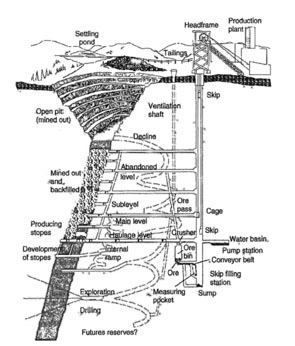
The footwall and hanging walls are not labeled, but I am sure you can identify them after our previous discussion. The answer to the question of why the permanent structures such as the shaft are located in the footwall side of the deposit is: as areas are mined out within the deposit, it is likely that some caving will occur, and the caving can be a consequence or cause of fractures propagating through the hanging wall, and potentially ending at the surface. If there were any structures such as a shaft in the hanging wall of the deposit, they would be destroyed by the normal mining operation.
You’ll note the main levels versus the sublevels, and don’t miss the decline. Also, take note of the exploration-drilling program that is ongoing throughout the life of the mine.
I like the next figure because it shows the footwall drift clearly as well as the sublevels and some of the unit operations within the sublevels. The ore passes down to the haulage level are easy to see in this figure, too.
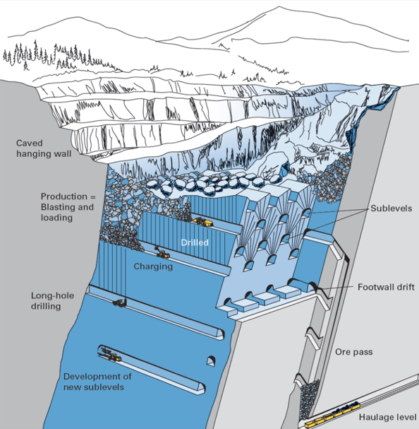
Finally, this third figure allows me to illustrate and elaborate on more of the terms. In thick-bedded deposits, it is often necessary to mine the bed in multiple steps known as lifts or benches. In this example, they are taking the seam in two lifts, and you can see the work underway on the benches. Specifically, you should be able to identify the locations where they are breast stoping, underhand stoping, and overhand stoping. You can also see the pillars that are being left behind to support the overlying strata.
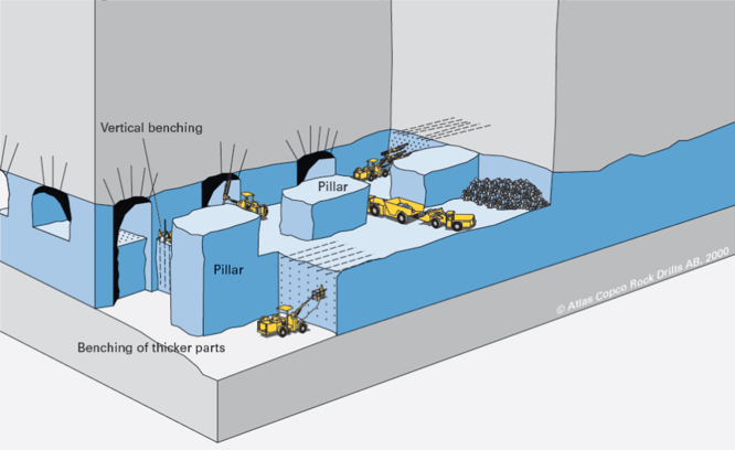
Now that we have a common vocabulary to describe the elements of underground mines, as well as an understanding of these basic elements, we are ready to look at the underground mining methods. In the next two lessons, we will look at the methods. I think it is useful to put the methods into a context of their usage within the industry. That is to say, some methods are rarely applied, and others are frequently applied. Let’s finish up this lesson by taking a closer look at this.
8.2.4: Prevalence of Underground Mining Methods
8.2.4: Prevalence of Underground Mining Methods
The actual number of underground mines will fluctuate somewhat year-to-year, as a few close and a few open. In recent years, there has been a more significant shift in the number, as several underground coal mines closed due to market conditions. Even though the actual numbers will vary, the proportions are relatively stable. For the purposes of this illustration, we will use underground mines in the U.S., and I’ll round up the number slightly for ease of comparison. There are approximately 600 underground mines in the U.S. Of those, approximately 400 are coal and approximately 200 are noncoal. The noncoal includes metals, industrial minerals, and stone mines.
Every one of the 400 coal mines utilizes the room and pillar method, neglecting the 2 or 3 underground anthracite mines that employ a hybrid method. All of the other underground mining methods are distributed among the 200 noncoal mines. Let’s look at that group in more detail.
| Unsupported Methods | Supported Methods | Caving Methods |
|---|---|---|
| Room and Pillar (150) | Cut and Fill (including sub-methods/variations (23) | Block Caving (2) |
| Shrinkage Stoping (2) | Sublevel Caving (0) | |
| Open Stoping (including sub-methods/variations) (18) | Longwall (all of the longwalls, coal and noncoal, are in mines that use room and pillar for the development of the panels) |
The disproportionate number of room and pillar mines is quite noteworthy. Roughly 75% of the underground noncoal mines employ this method. If you add the coal mines into the mix, roughly 90% of all underground mines are using the room and pillar method. Let me ask you a question. If you were to become an expert in the design of one mining method, which would you choose? Well, certainly your career options would be much better if you chose room and pillar! This is not to say that you don’t need to learn about the other methods! You do!!! However, in our curriculum, we do emphasize this method more than the others, and now you know why!
Let’s look at the commodities mined by the three most prevalent methods: room and pillar, cut and fill, and open stoping; as well as the two rarely used methods (in this country) of shrinkage stoping and block caving.
| Method | Commodity | Number |
|---|---|---|
| Room and Pillar | Limestone & Gypsum | 105 |
| Salt | 16 | |
| Lead/Zinc | 12 | |
| Trona | 5 | |
| Potash | 4 | |
| Silver/Gold | 3 | |
| Copper | 1 | |
| Open Stoping | Gold | 9 |
| Zinc | 7 | |
| Nickel | 1 | |
| Platinum | 1 | |
| Shrinkage Stoping | Gold | 2 |
| Cut & Fill | Gold | 19 |
| Silver | 2 | |
| Platinum | 2 | |
| Block Caving | Molybdenum | 2 |
Please be aware that not all commodities are accounted for in this table. There are additional industrial minerals mined by an underground method, which are not accounted for in this data. Despite the very small discrepancies in the totals, the data illustrates accurately the prevalence of the mining methods by commodity.
Review your knowledge of Module 8 terms by engaging with the interactive activities.
Lesson 8.3: Mining by Unsupported Methods
Lesson 8.3: Mining by Unsupported Methods
You will recall from Lesson 4.3 of Module 4 that underground mining methods are traditionally placed into three classes: unsupported, supported, and caving methods. These classes reflect the competency of the orebody and host rock more than anything else. If you excavate an underground opening in the ore or the rock is the opening stable -- i.e., will it remain open for an extended period, or will it begin to fall in? If it is unstable, i.e., the surrounding ore or rock breaks up and falls into the opening, how much support would be required to keep the opening from caving in? The answers to these questions lead us to choose mining methods from one of the three classes.
We are going to focus on the class of unsupported methods in this lesson. If the rock is essentially self-supporting and only requires the addition of minimal artificial supports to achieve a stable opening, then one of the methods from the unsupported class will most likely be applicable.
The three important methods within this class are room and pillar, shrinkage stoping, and open stoping. After a brief summary here, we’ll look at each in more detail. We will not talk in detail about the unit and auxiliary operations associated with these methods, as these were covered earlier in the course. Suffice it to say that a conventional mining cycle is used for shrinkage stoping and open stoping, whereas both continuous and conventional cycles are employed with the room and pillar method, depending on the commodity being mined. Examples of commonly used equipment will be noted for the different methods.
Room and Pillar Mining
This method of mining is used to recover bedded deposits that are horizontal or nearly horizontal when the orebody and the surrounding rock are reasonably competent. Parallel openings are mined in the ore, i.e., rooms, and blocks of ore, i.e., pillars, are left in place to support the overlying strata. Other than the pillars, little artificial support is required and often consists of bolts placed into the overlying strata to pin the layers together, making them behave like a strong laminated beam. A few examples of commodities mined by this method include coal, lead, limestone, and salt. Historically, if the pillars were irregular in size and placement, which is more likely to occur in certain metal and nonmetal deposits, this method was known as stope and pillar, rather than room and pillar. You will still hear the word stope and pillar being used, but the distinction is now largely irrelevant. This method accounts for the vast majority of all underground mining in the U.S. – and I believe globally as well, although I have not done that analysis. Examples of commodities mined by this method include coal, limestone, salt, trona, lead, and potash.
Shrinkage stoping
Shrinkage stoping is used to recover steeply dipping orebodies when the ore and host rock are reasonably competent. A stope, i.e., a large section of the mine where active production is occurring, is mined, but the broken ore is not removed, but rather is left in place to support the walls of the stope until the time when all of the broken ore will be removed. Since rock swells, i.e., increases in volume when it is broken, it is necessary to draw off some of the broken ore as the stope is progressively mined. The name of this method derives from this drawing off or shrinkage of the stope. A modern and important variant of this method is known as vertical crater retreat (VCR) mining. A few examples of commodities mined by this method include iron and palladium.
Open stoping
This type of mining is used to recover steeply dipping orebodies in competent rock. The ore is removed from the stope as soon as it is mined. Sublevel stoping and big-hole stoping are the important variants in use today. A few examples of commodities mined by this method include iron and lead/zinc.
8.3.1: Room and Pillar Method
8.3.1: Room and Pillar Method
Room and pillar mining is arguably the most important underground mining method in practice today. The majority of underground production comes from room and pillar mines, and the majority of underground mines, by number, employs the room and pillar method! Think about that!
Let’s start out by looking at this sketch of a section in a room and pillar mine. Immediately, you can see that only part of the deposit is mined. Openings are driven in the direction of mining, as shown, and unmined pillars are left in place to support the overlying strata.
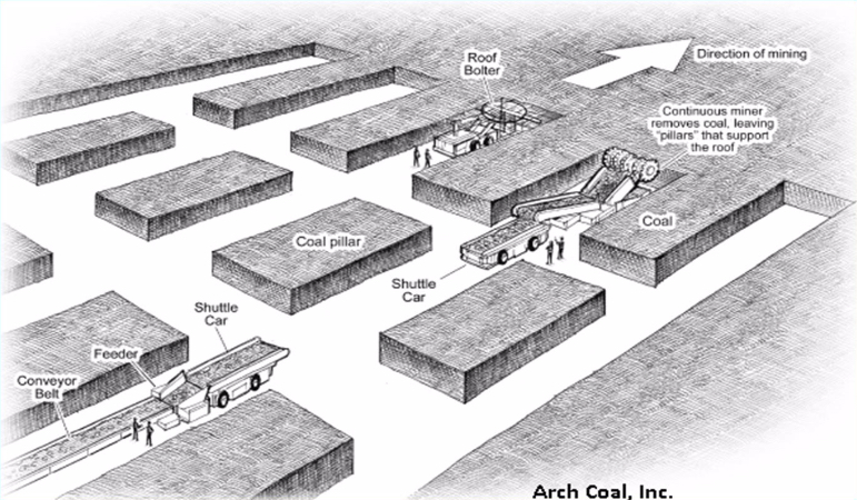
Remember from our earlier discussion of ground control: when we mine an opening, the weight of the overlying strata must be supported; otherwise, it will cave. As long as the rock layers over the opening are sufficiently strong (think beam), the weight of the overlying members will be transferred to the points where the beam is supported. Those points are the pillars. And from an engineering perspective, it is essential that you do not make the beam too long, because if you do, the beam will fail in the middle, and you will have a cave-in. Just to make it more interesting, you should know that in addition to choosing an appropriate opening width, which is governed by the allowable span of your beam, you also have to worry about the pillar. In some cases, the pillar is not strong enough to bear the weight being superimposed on it, and it will fail. And, in some cases, the pillar will be sufficiently strong, but the layers comprising the floor will not be, and the pillar will push through the floor. Lots of things to think about! This is one reason why, if you are going to be a mining engineer, you will take a course in rock mechanics and cover ground control design in the underground and surface mining courses.
Anyway, back to our sketch of the room and pillar section. The diagram shown is labeled specifically as a coal mine. In fact, it could just as well be salt, trona, lead, and so on; but with some differences that we will discuss. The active mining areas of coal mines are known as sections. In this diagram, you see one working section. This section consists of the equipment and personnel required to conduct the mining activity. From our earlier discussions of unit and auxiliary operations, you will recognize this as a continuous mining operation; and in the U.S., there are no remaining conventional mining sections in underground coal mines.
The mined-out areas in the sketch are given special names, and these may vary depending on the type of deposit that is being mined. There is one term of special significance: the mined-out areas in the direction of mining are known as rooms. Hence, the name of the mining method, room and pillar. Very clever… Typically, the pillars are laid out in this regular checkerboard pattern in coal mines, and now in most other commodities as well. That was not always the case for the noncoal mines. The size, spacing, and even location of the pillars would vary significantly, as would the dimensions of the openings. In those mines, the method was known as stope and pillar. Although you will still hear the term being used, the distinction has largely disappeared, and the term room and pillar is normally applied across all deposit types employing this general method. As a point of interest here, I would mention that mining engineers now recognize that there are serious shortcomings to the somewhat random placement of pillars, resulting in unnecessary ground failures, e.g., cave-ins. As a result of the art and science developed in underground coal mines, ground control approaches such as the pressure arch approach are more generally applied in all commodities, and this results in a more uniform placement of pillars. You will learn more about this if you take a rock mechanics course.
I want to talk about a few more terms. We’ve defined rooms and pillars. The openings driven between rooms are known as crosscuts. Here, they are shown at an angle of 90 degrees, and that is common; but if you are using continuous haulage, such as the flexible conveyor trains that we covered earlier, then you’ll be driving the crosscuts at a different angle of say 60 degrees. Recall also, that the point at which the material is being freed from the deposit is known as the face. In the sketch, you can see five faces. The continuous miner is mining at one face, and a roof bolter is bolting at another face. Alright, there are just a few more terms, and then we fill in some additional detail for the method itself. Let’s look at this plan view of a room and pillar section.
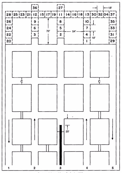
The sequence of rooms in the direction of mining is known as an entry in a coal mine. They take on the appearance of well-laid-out streets in a city. Indeed, you can stand in an entry and see for quite a distance. If you are in a noncoal mine, you may refer to entries as well, but more likely you’ll call them drifts or headings. What about the sequence of crosscuts? What special name do we assign to that? We don’t assign a special name, and the primary reason is that they do not form a continuous path in the way that rooms do for entries. The reason for that will become clearer within this lesson.
The collection of rooms and pillars shown in this figure form a panel. In this case we have a five-entry panel. Depending on the mining plan this panel could be 10,000’ or more in length, but its width will be determined by the width of the pillars and entries. Three-entry panels are common, as are four and five. There are additional details of note on the plan view.
- There are two different symbols, which appear in the cross cuts: the double line is a solid barrier known as a stopping, and often constructed of concrete blocks; and the single line with a “C” is a flexible curtain, known as a check curtain. Both of these are used to route and separate ventilating air. Recall that you need to provide fresh air to the working places, and then you need to exhaust the air that has become fouled with dusts and gasses.
- The directional arrows are illustrating the direction of the ventilation streams, sometimes called air courses. The air moving toward the face is known as the intake, and the stale air that has already passed the working face is known as the return.
- The thick solid line in entry number three is the conveyor belt.
- The numbered blocks are representing a cut sequence, i.e., block 1 is mined and then block 2, and so on. The cutting sequence will vary by mine, so you don’t need to know this cutting sequence. Simply, it is illustrating that there is a pattern to be followed. This pattern will be designed to optimize productivity and safety.
- The dimensions that are shown will vary somewhat by mine and certainly by commodity; and again, you don’t need to remember these specific numbers.
Finally, in terms of this overview, let’s look at this next figure. Notice that we are no longer representing the entries and cross cuts the same way. We’ve replaced them with a single line. That makes it easier and faster to draw these diagrams. As you look at this figure, you will see some of your newly acquired concepts, including Panels, Sections, Intakes, Returns, and Stoppings. There are also three new terms: overcasts, mains, and submains. Overcasts are yet another type of ventilation control joining curtains and stoppings as controls to route ventilating air. Specifically, overcasts are used to route on type of air over tip of another. It’s similar to a pedestrian overpass to allow people to walk over top of a busy highway. The overcast allows us to route, for example, intake air over top of a return aircourse without mixing the two airstreams. To satisfy your own curiosity, go ahead and trace the airflows in the part of the mine represented in the figure.
Now, on to the two other terms that I really wanted to highlight in this figure: the mains and submains. These are common terms in every coal mine and in some industrial mineral mines, e.g., trona. These words are simply designating their importance in the overall mine plan. The mains serve as the primary means of distributing utilities throughout the mine as well as being the location for the primary transportation and materials handling routes. The submains branch off of the mains to provide these same services to a group of panels, and the panels of course are the location for the active production sections. These word, mains and submains, and sometimes panels, are used as adjectives as well as nouns. The major aircourses supply air for the mine are known as the main intakes and main returns, for example. Main haulage of the mine may be a 72” belt, whereas the belts in the submains may be 60”, for example. It is no coincidence that the mains have more entries than the submains, which usually have more entries than the panels. Mains with seven to eleven entries are common. Often, three or four parallel entries are required to serve as intakes in larger mines, with two or three parallel returns, and another two isolated entries for material handling -- one being a belt entry and the other a track (rail) entry.
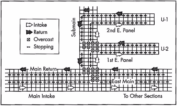
We now have a basic understanding of the layout for room and pillar mines, and we know the key terms that are used to describe them. We also know either continuous or conventional production cycles can be employed. With this as a solid foundation, let’s complete the picture with the conditions necessary to use a room and pillar method.
This is an underground method for which you can find mines as shallow as 60’ and at depths of greater than 2500’, and so we can conclude that depth is not a particular defining characteristic for the use of this method. The method does require tabular deposits, as opposed to the porphyry or vein deposits; and further, the method requires that the ore be fairly uniform in quality and thickness. Those are defining characteristics. Deposits with little dip (< 15) are necessary, and less dip, the better. There are rare examples of room and pillar being applied to steeply pitching (dipping) coal seams, but they need not concern us at this time. The rock strength needs to be moderate to strong. The rock needs to be strong enough to allow a reasonable span of opening between pillars. The ore strength on the other hand is not quite as important in the choice of the method. As the ore strength declines, it will be necessary to leave larger pillars, and at some point, that becomes uneconomical. In real-world situations, however, the ore strength is rarely an important characteristic for the selection of this method.
Before reading on, please pause for a minute and think about the characteristics that will lead you to select or exclude the room and pillar method from consideration. Specifically, think about the relationship between that characteristic and the design or operation of a room and pillar mine.
I identified the shape of the deposit as important in the selection of this method, and I said that uniform thickness is desirable. In fact, the thickness can vary by 10 or 20%, and not eliminate room and pillar as a viable method. In some cases, the quality of the ore declines rapidly as you approach the interface between the ore and host rock. In those cases, it is not unusual to leave anywhere from several inches to several feet unmined. In still other instances, the competency of the rock in the immediate roof may be very poor, and in those cases, that material will be mined along with the ore. Yes, that will dilute the run-of-mine product, but the additional cost of doing so, may be less than the cost of the ground-control problem that would result from attempting to leave the “bad” roof layer in place.
I did not say anything about the thickness of the orebody. Room and pillar is used successfully in deposits as thin as 24” and as thick as 100’ or more. It is clear that the orebody thickness is not a defining characteristic of the method itself. However, the mining plan and cycle will be affected as the thickness increases. Consider this: you have a continuous miner with a reach of say 15’. Your seam is 25’ thick. How you are going to mine that seam? Are you going to take 15’ out of the 25’, perhaps down the middle, and leave the remainder? Although there might be an instance in which you would do that, generally you would not invest the capital to access the orebody, and then voluntarily leave a lot of it behind! So, back to the question… what are you going to do?
Why not take it out in layers? That is what we do, and we refer to it as benching. We can do this, and it is frequently done with the continuous or conventional cycles. In some instances, both are used, i.e., the top lift or bench is taken with a continuous cycle and the bottom bench is taken with a conventional cycle. In these thicker seams, three of more lifts may be taken. Take a look at this figure.
It is apparent that the first bench is taken at the top of the deposit. This is the norm for room and pillar mining. For one thing, it is easier to scale and bolt the roof form this first bench. This figure is illustrating a conventional cycle, and we can see a couple of interesting practices. Note the drifting or breast stoping occurring on both the top bench and on the lower bench right side. As a contrast, look at what’s happening on the left side and front of the top bench: underhand stoping. They are also showing some overhand stoping, but, to be honest, I have no idea why! If they were moving upwards in the orebody that would make sense… Just ignore that part of the figure! Anyway, this is a good example of benching used in room and pillar mining.
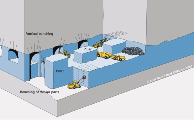
A defining characteristic for the selection of the room and pillar method, as I explained earlier, is a relatively flat lying deposit. What if you meet the characteristics of the unsupported class of methods, except that you have a steeply dipping orebody? You will look more closely at selecting an open stoping or shrinkage stoping method. Next, we will look at these two unsupported methods that are only applicable to steeply dipping deposits that are greater than 50 degrees, and frequently near vertical. The dip angle of the footwall must be greater than the angle of repose for the broken ore because these methods depend on gravity flow to collection points (draw points).
8.3.1a: Typical Equipment
8.3.1a: Typical Equipment
Before moving on to look at the methods suited for these steeply dipping deposits, I do want to identify some typical equipment used in room and pillar mining. There is a significant variation in equipment usage across room and pillar mines. This should not surprise you, given the big differences in the deposits. As you might expect, the equipment used to mine a 5’ thick coal seam is quite a bit different than that used to mine a 50’ thick lead-zinc deposit.
| Continuous Cycle | Conventional Cycle |
|---|---|
| Continuous mining machine | Jumbo drill |
| Road header | Wheeled loader |
| Shuttle car | Haul truck |
| Flexible conveyor train | Mine truck |
| Roof bolter | Scaler |
| Roof bolter | |
| Powder loader |
In the list of “typical” equipment, you saw an item that has not been discussed yet. A rock duster, which is an essential piece of equipment for an auxiliary operation in underground coal mines. Given the importance of this auxiliary operation to underground coal mining, let’s say a little more about the need for it, and the practice of rock dusting.
After we conclude our discussion of rock dusting, we’ll resume with the unsupported methods of shrinkage and open stoping.
8.3.1b: A Practice and the Auxiliary Operation to Prevent Explosions
8.3.1b: A Practice and the Auxiliary Operation to Prevent Explosions
Fine dust that is suspended in the air can be very explosive. Coffee, coal, cotton, and flour are important examples of dusts that are explosive, and are examples of deadly explosions that do occur in industrial settings. Many processes that involve milling, grinding, and cutting, for example, can generate fine dust particles. Under the right conditions, they can fuel powerful explosions.
Fine basically means that the dust particle has a very large surface area to volume ratio. We all have practical experience with fine dust. If there is sunlight shining into your room, pick up a towel, sheet, or piece of clothing and shake it. What do you see? Dust particles floating in the air, right? Eventually, those dust particles settle onto your desk or other furniture, and then periodically you take a cloth a wipe the accumulated dust away. There are corollaries between your practical experience and the industrial issue with dusts, and we will identify them.
The dust particles that are suspended in the air, and then eventually settle are known as float dust. The exact size of the float dust is somewhat dependent on the material. For coal dust, we are interested in particles that are 75 microns or less in size. The cutting action of carbide-tipped bits, as used in continuous mining machines, and shearers, creates not only large pieces of coal, but also a range of much smaller particles. Some of these are less than 10 microns and are respirable, i.e., they are trapped in the lungs when we breathe air containing these particles. Long-term exposure to excessive concentrations of respirable dusts will lead to fatal lung diseases, e.g., black lung (coal) or brown lung (cotton). The concentration of respirable dusts is heavily regulated, and engineering controls are used to ensure that hazardous concentrations do not occur. As we’ll see, the concentration of float dust is regulated as well. The creation of these dusts is an unavoidable consequence of the cutting or processing of the materials. Therefore, if we want to avoid bad outcomes, we have to take steps to ensure that the dust does not cause harm.
Before we can mitigate the affects of float dust, we need to know a little more about the genesis of dust explosions. In general, we must satisfy three conditions to have an explosion. We need a fuel, an oxidizer, and an ignition source. In this case, the dust serves as the fuel and the oxygen in the air serves as the oxidizer. Ignition sources can be varied. A spark created when a carbide bit strikes a hard rock at the interface of the coal seam and the roof, a spark from a motor or piece of electrical equipment, or in the old days, a match used to light a cigarette. It takes a very small amount of energy to ignite a dust cloud, or for that matter, a methane-air mixture. Given this information as background, what can we do to prevent a dust explosion?
Well, we have three choices, don’t we? Eliminate the fuel, the oxidizer, and/or the energy source. We can’t eliminate the oxygen, because it is in the air that our miners are breathing. We can’t eliminate the fuel, or can we? We can eliminate the energy source, so let’s talk about that one first.
We can ban the use of smoking materials in the mine or plant. In coal mining, smoking was banned with the 1969 Coal Mine Safety Act. This eliminated many explosions in coal mines. Next, we can mandate the use of special electrical equipment. We can require that all electrical equipment used in certain areas be placed inside of explosion proof enclosures. Unfortunately, no one has devised a way to prevent frictional ignitions, i.e., when a cutting bit creates a spark when striking certain rock masses, such as quartz or pyrites. Dramatically reducing the likelihood that an energy source will exist is doable; but guaranteeing that there will never be an energy source is not. Therefore, we have no choice but to try to eliminate the fuel source. While it is impossible to complexly eliminate the fuel source, we can dramatically reduce the chance of satisfying the three concurrent conditions necessary for an explosion, if we dramatically lower the likelihood of two of the conditions.
We cannot stop the generation of float dust, although researchers are attempting to devise ways to control it at the source. We can take two important steps after it has been created. Before talking about those steps, let’s first look at the anatomy of a dust explosion; and I need to preface that discussion with this fact: dust explosions follow from a methane explosion. We will use that as our starting point.
- A small volume of methane is ignited, perhaps by a frictional ignition. 99.999% of the time, our properly engineered and operated ventilation system is diluting the gas as it is liberated during cutting, and the ignition amounts to no more than a “little pop and flash of light.” If there is a little more methane present, the initial ignition will grow in size. High temperatures are produced and the gas and surrounding air will rapidly expand. The force of this explosion and the attendant damage will depend on the volume of methane present. We take significant steps to prevent the presence of an explosive mixture of methane and air, but sometimes multiple people fail to perform their responsibilities, and the unthinkable happens.
- The rapidly expanding gases create a shock wave, which produces a wind out in front of the fireball. The fireball will dissipate as soon as the methane is consumed, and the damage could be confined to a relatively small area; unless another fuel source is present. Any guesses on the other fuel source? Yes, accumulations of float dust.
- The traveling shock wave “stirs up” and dissipates accumulated float dust. A moment later, the fireball comes through and ignites this dust cloud, producing a violent explosion. At this point, the explosion may transition from a deflagration to a detonation. When it detonates, the shock wave will be moving faster than the speed of sound! The propagation of the explosion at this point does not require any methane – only dust. The moving explosion will entrain float dust and essentially at that point, it is carrying its own fuel! Even if it reaches a point where there is no float dust, there will be sufficient fuel entrained to allow propagation over a considerable distance. And, of course, if additional dust is encountered, the explosion will continue that much further. The amount of energy involved, as you might imagine, is staggering. A dust explosion can travel over miles and miles of entries, leaving nothing but twisted metal and charred remains in its path.
If you were standing downstream of a mine explosion, you would see the flame front approaching at a speed in excess of 1200 ft./sec. You can see the effect of the shock wave out in front of the flame front.

Often, these explosions will ultimately vent to the outside. Here is one such event – a research experiment, not an operating mine explosion, at the U.S. Bureau of Mines’ experimental mine near Pittsburgh. Much of what is known about these explosions and their prevention was developed by researchers at this facility.
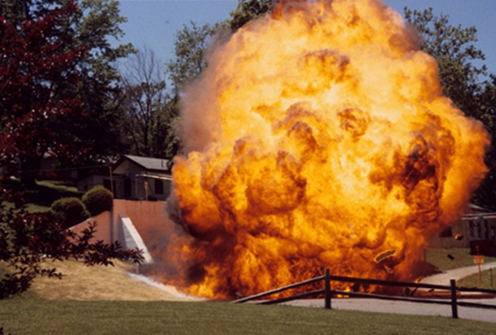
Fortunately, these explosions are rare in the U.S. The last coal dust explosion occurred in 2010. You have to go back four decades to find the one before that (actually there were a few smaller gas explosions during that period as well). Unfortunately, they have not been eliminated.
So, what more can we do to prevent these horrible events? Hopefully, this more detailed explanation of explosions has given you an idea or two! What do you think?
First off, we need to clean up accumulations of float dust. In fact, the law requires such cleanup to occur, and you will be fined if an inspector finds excessive accumulation of float dust. This is a very important “housekeeping” function. While you can successfully cleanup float dust accumulations near belt drives and along the belt line, it is impossible to prevent fine layers of dust from accumulated on the mine ribs and floor. Consequently, we need another approach, and that is the application of rock dust, which is known as rock dusting. We apply rock dust with rock dusters. I admit these terms are not very imaginative, but at least they will be easy to remember!
What is this rock dust and why is it effective? Rock dust is usually limestone that has been crushed to a fine powder. When we rock dust, we are applying, and literally blowing, this powder onto every surface in the coal mine. What purpose does this serve? Well, first off, this dust is inert, i.e., it is not combustible. Let’s assume that we’ve applied rock dust to all surfaces, and with this practice in place, let’s revisit the propagation of the explosion.
As explained previously, the shock wave moving ahead of the flame front disperses any dust into the air, and then the flame front ignites the dispersed dust cloud, and the explosion continues to propagate. But, what if the dispersed dust were an inert material like rock dust? Two good things would happen. First, the explosion would be deprived of new fuel, and second, the mass of the rock dust will reduce the temperature of the flame front. The net effect is that the explosion is quenched. Thus rock dusting can prevent dust explosions; but only if it is applied in sufficient quantity. Based on NIOSH research, MSHA regulations require that sufficient rock dust be applied so that the resulting mix of float dust and rock dust contains a minimum of 80% of inert, i.e., incombustible, content. Rock dusting is an essential and critical auxiliary operation in coal mining, and the law requires that all areas within 40’ of the active mining face be rock dusted.
You may be interested to know that you cannot use just any rock dust for this purpose. The law defines the specification for rock dust as follows:
Pulverized limestone, dolomite, gypsum, anhydrite, shale, adobe, or other inert material, preferably light colored, 100 percent of which will pass through a sieve having 20 meshes per linear inch and 70 percent or more of which will pass through a sieve having 200 meshes per linear inch; the particles of which when wetted and dried will not cohere to form a cake which will not be dispersed into separate particles by a light blast of air; and which does not contain more than 5 percent combustible matter or more than a total of 4 percent free and combined silica (SiO2), or, where the Secretary finds that such silica concentrations are not available, which does not contain more than 5 percent of free and combined silica.
I am not going to test you on the specific details of this definition, but I thought that you might be interested to know the standard.
Rock dusters come in a variety of shapes and sizes, but consist of a storage vessel for the bulk rock dust, a feeder, and a compressed air system to entrain the rock dust in an air stream. Application can be through hoses directed by a miner or broadcast in all directions around the rock duster. In some instances, it is desirable to apply rock dust continuously, and in those cases, trickle dusters dispense a small but continuous stream of rock dust into the air stream. This is done, for example, in certain return aircourses and belt entries.
One of the most surprising sights to people going into a coal mine for the first time is that the mine is white rather than black! Rock dusting is the reason for that!
It’s tough to find a really good video illustrating rock dusting. This one here (2:53) does a reasonably good job at the 2-minute mark; and the other operations that you can see in this clip are worthwhile watching as well.
Ok, let’s continue with our study of unsupported mining methods!
8.3.2: Shrinkage Stoping
8.3.2: Shrinkage Stoping
Shrinkage stoping is a vertical stoping method, conducted in a vertical or near-vertical plane, and at an angle greater than the angle of repose of the broken ore. A defining characteristic of shrinkage stoping is that most of the blasted (broken) ore remains in the stope to support the hanging wall and footwall. However, when ore is broken, for example by blasting, it swells, i.e., its volume increases. This swell may be as much as 30% or even more. Therefore, as mining progresses within the stope, it is necessary to draw off some of the broken ore – to make room for the next round of drilling and blasting as well as to create space for the next slice of ore to be blasted into. This drawing off was known as shrinking and hence the name associated with this method: shrinkage stoping.
Let’s take a closer look, using the following figure.
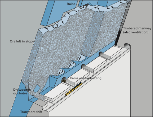
Although not shown, a shaft has been sunk on the footwall side of the deposit, and among other development workings a haulage drift has been driven, and then crosscuts into the orebody. Next, draw points and chutes were constructed by drilling and blasting in exact patterns. Then, the orebody within this stope is undercut. Raises are constructed at each end of the stope to provide manways for personnel access (ladders) as well as to provide ventilation and utilities, such as compressed air lines. This is a very labor-intensive method.
As an overhand stoping method, holes are drilled, loaded, and shot. A portion of the broken ore is drawn off to create sufficient space to allow the drilling and blasting operations in the stope. Once the newly drilled holes are drilled and loaded, the miners and equipment will be withdrawn. At that time, an additional portion of ore will be withdrawn to create sufficient space to account for the swell of the ore that will be blasted. Once this has been done, the round will be fired. Then a portion of the ore will be withdrawn to create space for the overhand stoping to continue. However, before the drillers re-enter the stope, any required ground control will be taken care of. Given that the ores are usually strong, little ground control will be required, other than scaling any loose materials. After it is safe to re-enter the stope, the cycle will repeat.
All right, let’s fill in some additional detail. First of all, why are we leaving ore in place? Essentially to keep the hanging wall and footwall from closing open stope, and causing a failure. Typically, the ore is strong, but the country rock, less so. This method works well with narrow veins, as thin as 3’ or thicker veins of 100’ or so. Stope lengths vary from 150’ to 300’ and heights of 200’ to 300’. In narrow veins, the stopes are laid out longitudinally, whereas in thicker veins they will be transverse. The key design parameters in shrinkage stoping are the dimensions of the stope, largely governed by the size and shape of the deposit. Although rock mechanics will enter the picture in determining size of the stope, the openings used are generally relatively small and are not excessively stressed. Therefore, the major concern is to maintain a manageable-sized stope that ensures a smooth flow of ore by gravity and effective draw control.
A high-quality ore, i.e., high grade and a valuable commodity, is necessary given the high cost of this method. It is labor intensive, and productivity is low compared to other methods. Furthermore, the ore needs to be uniform in quality, as the method doesn’t lend itself well to blending. There are a few other characteristics of the ore that are important. When blasted, the ore should not pack – if it does, you won’t be able to draw it off, and secondary blasting may be required. The ore may remain in the stope for six months to a year, and during that period it should not oxidize, as oxidation can create mineral processing problems, or worse, spontaneous combustion can occur, creating a carbon monoxide and fire hazard.
This method in its original form, as described here is, is unlikely to be used anymore. The last mine that I am aware of in the U.S. was a platinum/palladium mine in Montana. Despite the advantages of this method, it has two really serious disadvantages: one is safety and the other is productivity. Miners working in the stope after each blast presents a level of risk to their safety that cannot be justified by modern standard. From a productivity perspective, there are multiple problems. It requires the use of small equipment and multiple miners. The working surface for the miners is the blasted ore, which makes it difficult to move equipment. Given these serious limitations of the method, you should be asking yourself the question: why are we bothering to talk about this method? As it turns out, there is a modern variation of this method, which is quite successful, and accordingly, quite popular. The variant is known as the vertical crater retreat (VCR) mining method. It was invented by mining engineers working in the nickel mines in Canada. The company, INCO or International Nickel Company as it was known, obtained a patent on the method, and until the patent expired near the end of the 20th century, INCO had exclusive use of this new method.
Vertical Crater Retreat (VCR)
As a variation of shrinkage stoping most of what we said there, applies here, except for the differences that I am going to point out to you now. VCR is much safer because miners and equipment do not enter the stope, and VCR is amenable to a high level of mechanization. In these two differences, VCR has overcome the two primary disadvantages of shrinkage stoping that we identified. This is all well and good, but how does VCR achieve these two improvements? Let’s take a look at the following figure.
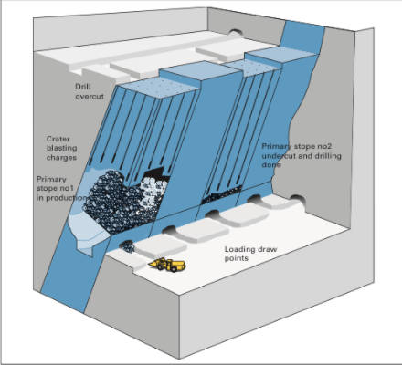
Before going into any detail, I should tell the underlying secret that made VCR possible: significant advancements in drilling technology, and specifically down-the-hole drills. You’ll see why this is so important in a moment.
The initial development of the stope for VCR is the same as for a shrinkage stope. The one addition is the need for an overcut at the top of the stope, for that is where all of the drilling and blasting will originate. Either from the shaft or a ramp, crosscuts will be driven over to the overcut level. The overcut will be mined out, and then this will serve as the location where the miners will work. Rather than being in the stope with the attendant hazards, the miners are on top of the stope working from a stable and safe location.
From the overcut, they will use down-the-hole drills to drill the full length for all of the holes that will be required to mine the stope. Drilling holes of that length, accurately, is difficult. If the position of the holes varies by more than a few percent, the rock fragmentation will suffer. Oversize material will result, and will likely cause serious problems when they try to draw down or shrink the stope. Excessive fines will be produced, and they will likely cause plugging and packing. As such, very accurate drilling technology must be used. That’s where the advances in DTH enable the success of VCR. Of course, DTH is only an enabler. It also took clever innovation in the blasting design, and specifically in the development and refinement of crater blasting.
The drilling pattern is a grid on the order of 12’ x 12’. The hole diameters are on the order of 6”. While there is engineering guidance in the literature for the design of these crater blast rounds, many of the best practices are closely guarded secrets within the companies using this method.
Once the holes have been drilled, the lowest part of each drill hole is charged with explosive. The explosive is detonated, and a portion of the fragmented rock is drawn off to make room for the next blast. The lowest part of the holes is again charged, the blast is set off, and the cycle repeats. Usually the blast would be designed to take off a 10’ slice of ore. The design and execution of the spherical charges is technically challenging, and there is significant art as well as science to a successful application of crater blasting.
As with shrinkage stoping, there is some revenue from the ore that is drawn off during the development of the stope, but the real “payday” comes after the stope has been completely fragmented. Then the broken ore can be drawn off and sent to the mill over a period of several months.
8.3.3: Sublevel (Open) Stoping
8.3.3: Sublevel (Open) Stoping
If we had a stronger and more competent host rock, we could dispense with the need to keep ore in the stope to support the hanging wall as we do VCR mining. Indeed, such deposits do exist, and when they do, we can employ the open stoping method. There are different variations, but essentially, we delineate stopes, and then through drilling and blasting, we slice off segments of the ore, and remove the blasted ore through draw points. We often divide the stope vertically by driving sublevels longitudinally, and then we ring drill with the sublevel, charge the holes, and initiate the blast. The progression of the sublevel blasting is coordinated spatially from sublevel to sublevel, so that the blasted ore from a sublevel is free to fall to the bottom of the stope where it will be drawn off.
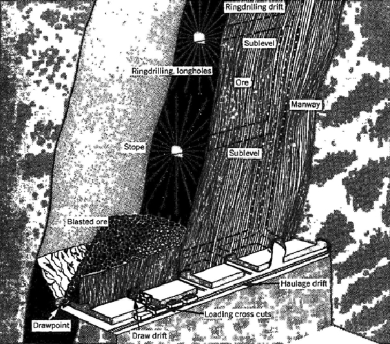
The vertical spacing between sublevels is limited by the accuracy of the ring drills. As with the innovation of VCR, the accuracy of DTH drilling technology led to a variant of sublevel stoping known as big hole stoping. As you can see in the following figure, the ring drilling has been replaced with long-hole drilling. Using DTH drilling the vertical spacing can be increased significantly, and this means less time and cost to develop the sublevels. The holes are typically on the order of 300’ in length and approximately 6” in diameter. A slice of approximately 10 to 15’ is blasted with each round. Ultimately the size of the blast is limited by concerns of blast damage, and as increasing amounts of explosive are detonated, the risk of damage increases.
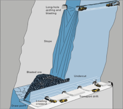
You can also notice in this drawing the vast open spaces created as the stope is mined out. As you recall, a condition for using open stoping is that the host rock be reasonably strong. Here, you can see why this is the case.
In our discussion of shrinkage and open stoping, including the variations of these two major methods, I didn’t say anything about pillars used to separate stopes. There will be a pillar remaining over the entire stope, and this is known as a crown pillar. The pillar underlying the stope is the sill pillar. Finally, there will be pillars separating the stopes transversely, which do not have a special name. Often, there is significant ore of considerable value contained in these pillars. Mining these pillars, however, presents a major challenge: if you attempt to take out the pillar, everything is likely to cave in. It’s rather difficult to recover the ore, if the entire mine in that area has collapsed!
Well, mining engineers are clever, and they have devised means of safely recovering the economic value remaining in the pillars. That’s an interesting story and one that we will tell in the next lesson when we look at cut and fill mining. Stay tuned!
Before moving on to the supported methods, let’s identify some of the equipment commonly found in these different stoping operations.
| Stoping Methods |
|---|
| Jumbo drill |
| Ring drill |
| Down-the-hole drill |
| LHD |
| Mine truck |
| Bolter |
| Powder loader |
Lesson 8.4: Supported and Caving Methods
Lesson 8.4: Supported and Caving Methods
We examined the unsupported class of methods in the last lesson and saw that this class is by far the most prevalent, i.e., those methods account for the vast majority of all mines. Nonetheless, the supported and caving classes are important in those circumstances that match these methods. Let’s examine each class in more detail.
8.4.1 The Supported Class of Mining Methods
8.4.1 The Supported Class of Mining Methods
Supported methods are those that require significant artificial support to maintain stability in the exploitation openings of the mine. We like to use pillars of the original rock mass as the ultimate form of ground control in an underground mine, because they are capable of providing near-rigid support. However, some orebodies are too weak to employ pillars for support. Often, the host rock is not very strong. Pillars are not an option, as a primary means of support, and consequently attempts to remove the ore will likely result in structural failure of the opening. It may not occur immediately, but over the time period that the opening would be needed, failure is likely to occur. Thus, the supported methods are used when production openings will not remain standing during their life. Support methods are also used when surface subsidence cannot be tolerated.
Whoa, but wait a minute. Didn’t we say that caving methods are applicable when the rock caves readily? Ok, then why would we use a supported method, rather than a caving method for these weak orebodies? Good question, for which there are two good answers! One is that caving to the surface will cause a subsidence zone, i.e., the surface will literally collapse and sink by an amount close to the thickness of material removed in the mine. If you are in the middle of “nowhere,” it doesn’t matter. If there are bodies of water, e.g., rivers and lakes, or towns, for example, you will not want to subside them! The second answer to the question is that supported methods can be extremely selective, whereas caving methods are just the opposite.
We could say that the supported class is employed when the other two classes of methods, i.e., unsupported and caving, are not applicable.
The supported class of methods is intended for application to rock ranging in competency from moderate to incompetent, and includes:
- Cut-and-fill-stoping
- Stull stoping
- Square-set stoping
Cut-and-fill and stull stoping is applicable to moderately competent rock, and square-setting is for the least competent rock. Mechanization requirements and labor costs have all but eliminated stull stoping and square-set stoping. Nonetheless, I’ll briefly explain them because it may give you some ideas if you ever want to recover a very small part of the deposit and no other approach is possible.
8.4.1a Cut and Fill Stoping
8.4.1a Cut and Fill Stoping
Cut and fill is a very expensive method, but is very selective. You might predict the type of deposits in which it would be employed as the principal mining method. High value metalliferous ores such as gold or silver are often mined by this, and when the high-grade ore is in veins, the high degree of selectivity of this method is a real asset.
The basic concept of cut and fill is straight forward: we mine a portion of the stope, and then we completely backfill the mined portion. The backfill may simply be broken rock, but more likely is a mix of cement and waste rock. This backfill serves to support the stresses that were originally borne by the ore, and we’ll talk more about the backfill material in a while. Deciding how much ore to recover before beginning the backfilling is an important engineering decision. If you take too much or leave the opening unsupported for too long, it will fail. If you error on the conservative side, your productivity will suffer, and the mining cost will escalate.
So, let’s take a look at one implementation of the cut and fill method. We define a stope by driving an upper and lower haulage level. This defines the height of the stope, and a height of 150’-300’ is typical. The length of the stope is running left to right in the figure below, and may be on the order of 200’-2000’. The width of the stope is going into the page, and in this drawing you cannot tell anything about the width. The width would need to be at least 6’ and may be as much as 100’.
What determines these dimensions? First, you will try to keep your stope within the mineralized zone of the orebody. Second, ground control considerations will prevent you from making the stope too large. Third, the equipment that you are using will require certain minimum dimensions. If the equipment is 8’ wide, then the narrowest dimension of the stope, which is the width, must be greater than 8’.
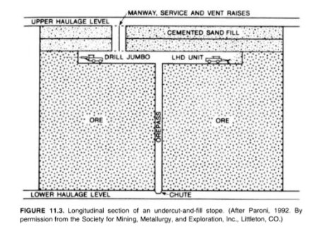
Looking at the figure, you can see the progression of mining activity. This figure is representing an undercut and fill cycle. Drifting or breast stoping is started with the jumbo drill. The holes are charged and shot, and then the LHD loads out or mucks the broken ore, and drops it down the orepass. The orepass is a raise that has been excavated for that purpose, and typically the raise will be protected with a grizzly at the top. This is done to prevent a large rock from plugging the orepass. If that happens, it is very dangerous. Someone has to go down into the orepass to drill and blast the plug. Anyway, as soon as we’ve completed mining the slice of ore, we will begin to backfill. The height of the slice that we take will be determined by ground control considerations, and is likely to be at least 10’ but no more than 30’. The ore will be collected at the lower haulage level and taken out of the mine. It is likely that mine trucks will be used, and there may or may not be a hoist involved in the operation.
Ok, now that you have the basic concept, there are a few variations. The figure illustrates mining moving downward, which we know as underhand stoping, and, in this case, we modified the term cut and fill to undercut and fill. In some deposits, we may choose to mine the orebody in an upward direction, which we know as overhand stoping. In this case, we modified the term cut and fill to overhand cut and fill. Finally, there are times when we progress in small slices, with an ultimate direction of up or down in the deposit; but, in this case, we often call it drift and fill. Don’t stress over the nuances of these terms, but you should already know what we mean by: overhand, underhand, and breast stoping; undercut and fill; and overhand cut and fill.
Here, below, is a deposit in which the ore is so weak that we cannot take a slice across the entire length of the stope, and have to take it in small slices – backfilling each as we go. This is an example of a drift and fill operation.
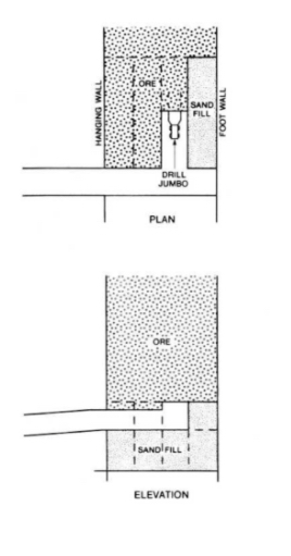
Next, we have a diagram of a modern cut and fill operation with a ramp in place. If you were to go into the underground gold mines in Nevada, for example, you would see mines similar to this. This particular example is using overhand cut and fill, but you will also see undercut and fill in practice there.
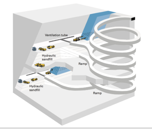
Fill and Backfilling
Significant research has gone into the development of fill materials, the engineering practices to use backfill, and the design of cut and fill mines. Let’s take a closer look at the fill.
Historically, waste rock mined underground, tailings from the prep plant, or rock quarried from a nearby location on the surface were used as backfill. In the former two instances, backfilling serves a secondary purpose of disposing of useless byproducts. Rather than accumulate large mountains of tailings on the surface near the mineral processing plant, we can use them productively in the active mine. Over the years, the practice of adding cement to these raw materials was incorporated into most operations. The addition of cement allows for a stronger backfill to be formulated and placed. It also can be used to provide a smooth working surface. If you are overhand stoping, for example, your equipment will be working from the last backfilled surface. By adding extra cement to this top layer, the equipment and miners will work more productively and safely.
Engineers generally consider three types of fill
- Hydraulic fill: tailings (55 - 70% solids) and 3-4% cement, with a 10% cement mix to top off the fill (smooth hard surface). Pumped underground as a slurry.
- Paste fill: unclassified tailings (up to 88% solids) with only a few percent cement. Requires precise mix and a more expensive plant but offers a stronger backfill and the use (recycling) of a higher percentage of tailings.
- Cemented rock fill: originally waste rock was used to fill the stope, and then hydraulic fill was sprayed on top to form the working surface. Today, the cement is often added at the surface, and then the backfill is dropped down a winze.
You don’t have to memorize these three types, but I’d like you to have an approximate idea of the mix for hydraulic fill.
Here, below is a photo of a paste fill plant, where the tailings are dewatered and mixed with the cement, and then pumped into the mine for placement.
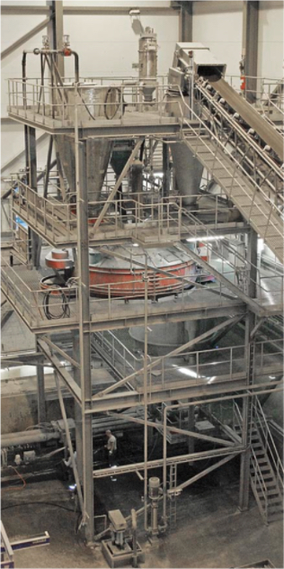
It is important to note that backfill can represent 10 - 20% of the mining cost, and of that cost, nearly 75% is the cost of the cement!
Cut and fill is an important mining method because it enables the recovery of high-value metal deposits in weak rock. The ability to be very selective with this further enhances its usefulness in many of these deposits, in which the spatial characteristics of the deposit require a more selective method. There is another important use of the method, and that is in pillar recovery.
I did mention earlier that often there is a significant value in the pillars that remain after the stope has been mined. In shrinkage stoping or open stoping, the crown and sill pillars as well as the pillars separating the production stopes contain significant ore. But how do you safely recover them? They are there to support the mine openings, and if you attempt to remove them, the openings will collapse. The solution is to backfill the mined-out area around the pillars. Then, with the backfill supporting the weight of the overlying rock, you can safely extract the pillars. Of course, the economics of doing so must be analyzed carefully.
This method of pillar recovery is also practiced in some metal mines employing the room and pillar method. A notable example is in the Viburnum Trend in Missouri – a famous lead-zinc mining region in the U.S. There they have roughly one million dollars of ore tied up in one pillar. Using a cut and fill approach, which is expensive, they are able to recover the pillars profitably.
8.4.1b Square Set Stoping
8.4.1b Square Set Stoping
This mining method was used to mine in the weakest of rock masses. It is extremely expensive, and you’ll see why in a moment, but was used to recover silver and gold deposits through the 1970s in the U.S. The concept of the method is simple: we will mine only a small volume and immediately build and place timbers into the opening to support it on all sides. The timbers will be precisely cut and fitted to form a cuboid. This process will continue indefinitely, resulting in mines with thousands of these square sets. The dimensions of the square set will vary, but 6’x6’x8’ would be illustrative. Take a look at this figure, which illustrates a small portion of a mine with the square sets. The timbers are large, at least 6” square and likely between 8”- 12” or larger. The cost of acquiring such timbers today would be cost prohibitive, but that cost would be small compared to the labor cost to build these square sets. Elaborate and precise joinery was required so that the strength of the square set as not compromised. Today it is difficult to find carpenters with the skill to construct such precise joints! Note in the figure the use of the lagging to keep the weak ground from flowing into the area supported by the square sets.
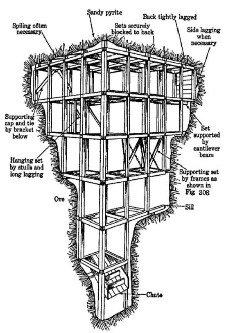
8.4.1c Stull Stoping
8.4.1c Stull Stoping
This method is designed for rock masses that are weak but somewhat competent – not as weak to require square sets, but not sufficiently competent to use cut and fill. The method is also conceptually simple. Place timber posts at close intervals to maintain the opening between the hanging wall and footwall. A serious shortcoming of this method is that the close placement of the stulls effectively prevents the use of mechanized equipment. Hand drilling with stoppers, drifters, or sinkers is required; and load is accomplished with labor-intensive approaches such as slushers, small overshot loaders, and so on. Needless to say, as a principal mining method, this one has also disappeared.

However, with this observation, I want you to consider that you could apply this approach to a very small area of a mine, where you had a unique challenge; and it could be a safe and economic solution to whatever your problem is. Instead of timbers, you might use hydraulic jacks. Regardless, there is value in having an awareness of these older but now obsolete mining methods. This reminds me of another very important point. Just because you select a particular mining method, and then successfully use it for a period of time… don’t think you are required to continue using that method if the conditions are changing. As a mining engineer equipped with knowledge of these methods, do not be afraid to change methods if the conditions warrant, or even to modify a method to suit your needs. The need for this, and the opportunity to do so, is most likely to occur in metal deposits.
8.4.2 Caving Methods
8.4.2 Caving Methods
So far, we have studied mining methods that require exploitation workings to be held open, essentially intact, for the duration of mining. Specifically,
- if the ore and rock are sufficiently competent, unsupported methods are adequate;
- if ore and rock are incompetent to moderately competent, then supported methods must be used.
We will now study a class of methods in which the exploitation openings are designed to collapse; that is, caving of the ore or rock or both is intentional and is the very essence of the method.
We define caving methods as those associated with induced, controlled, massive caving of the ore body, the overlying rock, or both, concurrent with and essential to the conduct of mining.
There are three current methods that are considered to be caving methods:
- Block caving
- Sublevel caving
- Longwall mining
Sublevel caving and block caving have application to inclined or vertical, massive deposits, almost exclusively metallic or nonmetallic.
Longwall mining is used in relatively flat-lying and tabular deposits such as coal, primarily, but the method is used to exploit some noncoal minerals, such as trona.
Longwall mining is a moderately priced method, and sublevel and block caving are among the cheapest of all the underground methods.
The caving class is truly unique because the exploitation openings are deliberately destroyed in the process of mining. Now, having said that, I suppose that before we go any further with this discussion of the caving methods, I should clarify one point. Do not think, even for one second, that because caving is the desired outcome, you are relieved of your engineering obligations for ground control! It is as important to apply rock mechanics to ensure that caving will occur as it is to prevent the occurrence of caving! In effect, the cross-sectional shape of the undercut area (i.e., the width-to-height ratio) must be sufficiently elongated to cause failure of the roof or back. Further, the development openings must be designed and located to withstand shifting and caving ground, as well as subsidence that usually extends to the surface. Thus, there is no shortage of significant ground control challenges with the caving methods. And it doesn’t stop with the engineering. In caving operations, the rate of production may be more important than in many other methods. Specifically, production must be maintained at a steady and continuous pace to avoid disruptions or hang-ups in the caving action.
Let’s take a look at each of the three methods in this class.
8.4.2a Block Caving
8.4.2a Block Caving
This method, which was developed in the U.S. after WW I, is well suited for mining in weak orebodies. Panels or blocks of ore are undercut. Once undercut, the weak orebody begins to cave under its own weight. The caved ore is drawn off through draw points. As the ore is drawn off, the orebody will continue to cave under its own weight. This process will continue until all of the orebody within the block or panel has been recovered.
Under proper conditions, this underground method can rival economically surface mining! It can do so because it is a bulk or high-volume mining method. But it is not a selective method. In the caving and drawing process, you take everything; and therefore this is not a viable method for following rich mineralized zones, for example. If you were in weak ground and you wanted to follow mineralized zones, which method would you first consider? Cut and fill? Yes! The method works well for low-grade ores where you have to mine large quantities cheaply to be profitable. Examples include low-grade copper and molybdenum deposits, diamond-bearing Kimberlite pipes, and certain iron ore deposits, among a few others.
Given the foregoing discussion, let’s summarize the conditions that we expect to see for a successful application of block caving.
- Massive orebody (both horizontally and vertically)
- Low grade ore (the method is not selective)
- Orebody must cave easily into manageable pieces
- block - largest cave volume, weakest ores
- panel - intermediate volume, weaker ores
- mass - smaller volume, weak ores
- The host rock, i.e., the hanging wall has to fracture and collapse, following the cave.
- Subsidence of the ground surface above the orebody has to be acceptable.
Note the breakdown of the orebody into the categories of blocks, panels, and masses. These relate to the size of the cave area. If the ore is very, very weak you can have a wide stope. On the other hand, if you try to have a wide stop with a moderately weak ore, you are likely to get bridging within the stope. Caving stops at that point and it develops into a very dangerous as well as production-killing situation. Thus, the cave volume has to be reduced as the ore becomes marginally stronger. In some mines, they will talk about their panels, and in others, their blocks. Now, you know the reason for this difference in the words they use.
Let’s take a look at a video of block caving before going on. This video will give you a good understanding of the method. The are some other details of note as well:
- Decline and shaft, and the purpose of each
- Ground control measures
- Drawbells
- Undercut level
- Ring drilling
- Materials handling
- LHDs
- Crusher - Orepass
- Conveyor Belt
- Ore skips (hoist)
- Subsidence zone
- Automation
Please watch the following video (3:44) entitled "Block Caving"
Here, below, is a view of a block caving operation, which depicts the information that you saw in the video, but in a slightly different form.
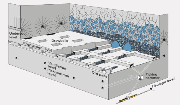
We can summarize what we learned from the video into the following steps for development and exploitation.
Development - Tasks
Development to prepare blocks for production caving is extensive and can take up to several years of advance work. On a per unit cost basis, the development for block caving is no greater than for sublevel caving.
- Sink Shaft and develop decline for access to the orebody from the footwall.
- Drive multiple headings to prepare haulage ways, cross cuts to develop undercut and draw points. Drive other laterals as needed.
- Develop the draw points and ore passes
- Install extensive ground control technologies to stabilize development openings, e.g., shotcrete, cable bolts, steel sets, arches, and so on.
This figure, below, shows these development activities.
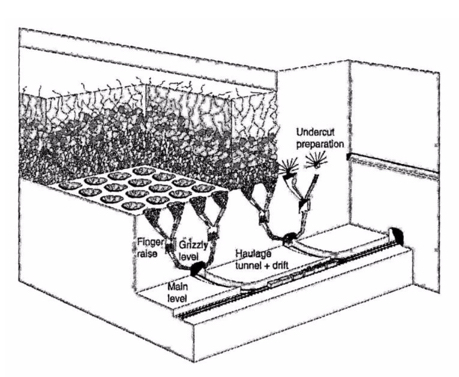
Exploitation - Unit Operations
- Drilling for the undercut using pneumatic- or hydraulic-powered percussion jumbos with a hole size 2 to 3 in.
- Blasting the undercut using ANFO or slurries; and bulk charging by pneumatic loader or pump with electric firing.
- Loading at the draw points with an LHD, or rarely today, a slusher.
- Hauling by LHD from the draw point to an ore pass, and then belt, rail, or truck to a hoist.
8.4.2b Sublevel Caving
8.4.2b Sublevel Caving
Sublevel caving shares many similarities with block caving, with one notable exception, which is responsible for this method: the orebody is competent and will not cave under its own weight. The host rock, on the other hand, is weak and caves behind the ore as it is extracted. Consequently, the orebody needs to be drilled and shot to extract the ore. Once extracted, the hanging wall caves. Given the similarities, we don’t need to say much, and especially if you look at this diagram of a sublevel caving operation, below. There are a few points to be made, however.
You will notice there is no need to develop and undercut, nor bells and drawpoints. Instead, a series of sublevels is developed, and next, the ore above the sublevel is fan or ring drilled. The holes are charged and fired. The broken ore is then loaded out of the sublevel using an LHD (or rarely, a slusher). The LHD’s travel to ore passes where the ore is dumped and then collected at a lower haulage level.
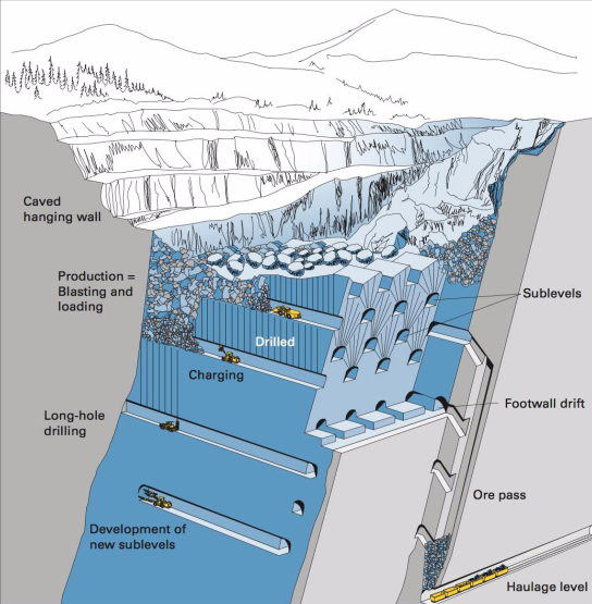
The world’s largest sublevel caving mine is located above the Arctic Circle in Sweden. The Kiruna Mine is mining the Kirunavaara iron orebody. (See figure below.) This mine is famous not only for its size and longevity, but it has been a hotbed of innovation for mining technologies over the years. I really like this figure because it tracks the mine’s development over the decades. You can see that the orebody was mined by open pit for nearly 50 years, and then they went underground. You can trace their progress over the ensuing 50 years up to the present.
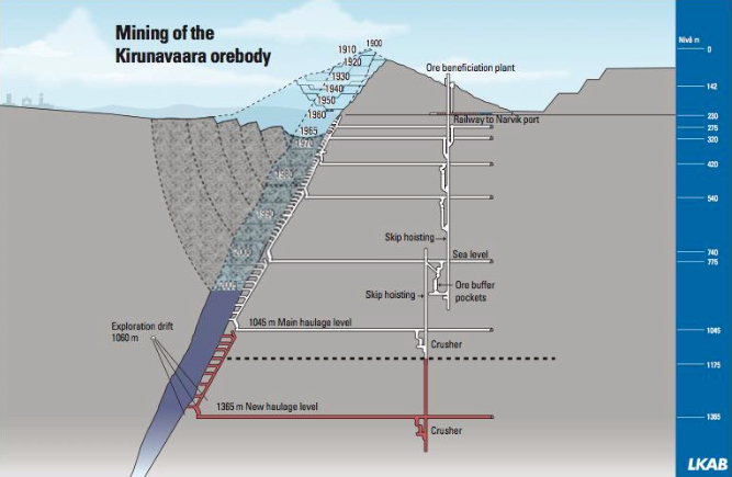
Looking at this next figure, you see the planned workings (sublevels) through 2019.
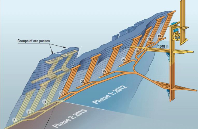
Block caving and sublevel caving require steeply dipping to nearly vertical deposits to enable the gravity flow of the rock. Longwall mining by contrast does not require this gravity flow of the caved material, and as such, it is well suited for tabular and nearly horizontal deposits.
8.4.2c Longwall Mining
8.4.2c Longwall Mining
Longwall mining applies to thin, bedded deposits, with uniform thickness and large horizontal extension. Typical deposits are coal seams, potash layers or conglomerates, trona, and gold reefs. Longwalls are found in nearly horizontal deposits of coal and trona, whereas in metal/nonmetal deposits, a steeper dip is tolerated. The difference is in the equipment that is used. Coal and trona are using massive suites of mechanized and semi-automated equipment that is unsuitable for use in greater than 5-10% grades. There are exceptions, but we’re not going to complicate this discussion with those.
Longwall mining takes its name from the characteristic long face or wall, which may be several hundred feet or more in length. The figure below illustrates this nicely. The ore is extracted in a slice along this long wall. The region adjacent to the face is kept open, i.e., free of obstructions, to allow space for miners and equipment. This region might extend 10’-20’ out from the wall. If we are looking at mining a gold reef, for example, a line of posts will be installed to support the roof or back and protect the active mining activity. At some distance back from the face, caving will be allowed to occur, and in most instances, this is necessary to relieve superimposed loads on the working face. If we are looking at a coal application, the process will be somewhat different. A significant percentage of the coal that is mined underground comes from longwall mines; and not just in the U.S. but around the world. As such, we’ll look more closely at longwall mining in coal.
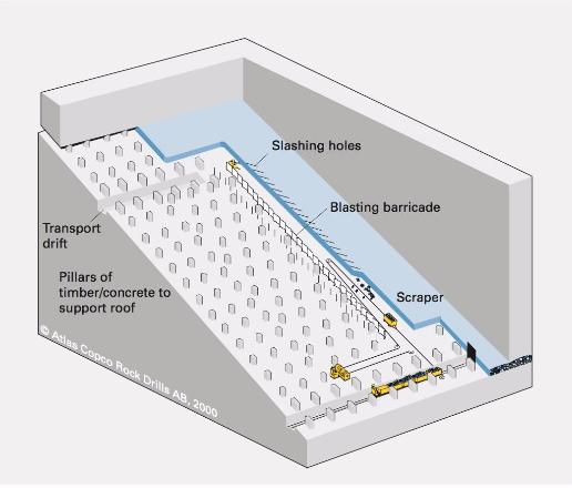
Longwall Mining of Coal
Longwall mining of coal is a high production and high productivity method, employing sophisticated electrical, mechanical, and hydraulic systems, as well as computer-based monitoring and control systems. Most modern (coal) longwall faces are semi-automated. It is noteworthy that longwall operations in trona mines utilize essentially the same equipment and processes that are used in coal mine longwalls. As the long wall or face is mined and the roof supports advance forward with mining, the roof in the mined-out area will cave.
When the panel is initially mined, caving will be delayed. This is a worrisome period because all of the weight of the unsupported roof is transferred to the face and also the gateroad pillars. Sometimes caving may not start for 10 - 20 or more passes of the shearer. If the superimposed load becomes too great, the face and pillars can begin to crush. Thus, for longwall to work safely and productively, the cave must occur in a timely fashion. Once it has started to cave, it will generally continue with each pass of the shearer. Ground control experts will conduct a cavability analysis of the overburden before a decision is made to employ this mining method. This requirement for caving is the reason this method is classified in the caving class of methods.
Please be aware that the longwall panels within the coal deposit are created by room and pillar mining. Thus, many room and pillar (coal and trona) mines are also longwall mines, and in most of them, the room and pillar work is simply to develop the panels and the infrastructure to facilitate operation of the longwall. By that, I mean you need to have a well-developed ventilation, materials handling, and power systems to support a high production longwall. The room and pillar mining creates the mains, submains, and panel entries for these systems. Let’s look at a few figures. These won’t answer all of your questions right now, but these in combination with some videos that will come afterwards, should give you a good understanding of the method.
Let’s start with a plan view of a mine. This figure, below, shows a portion of the mains or submains and the longwall panels. Notice the three-entry gateroads that define the panels. One set of these will be known as the headgate entries and the other as the tailgate entries. The one of the longwall face will be known as the headgate and the other end of the face will be known as the tailgate. The entries adjacent to the mined out panel are the tailgate entries, and that defines the tailgate side of the panel. The longwall face is mined on retreat. That is to say, the gateroads are mined on advance, and then the longwall face retreats back to the submains or mains.
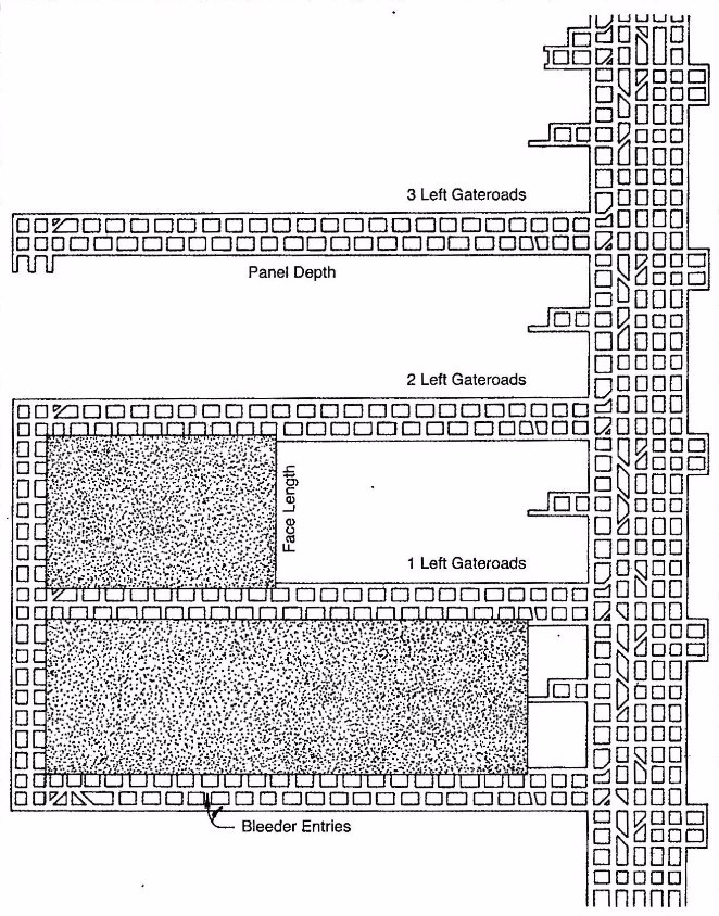
The equipment required for a longwall face is unique to this mining method. Let’s look at it in this figure below, and then when you see it in the videos, it will make more sense.
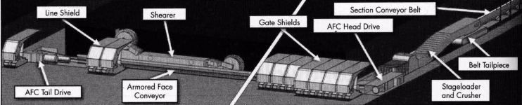
The armored face conveyor is a massive steel structure containing a chain conveyor. The shearer (or plow) rides on the AFC and cuts the coal. The cut coal falls into the AFC, and is transported to the headgate. At the headgate, the coal is crushed to a size suitable for transport on a conveyor belt and then fed at a controlled rate onto the belt. This panel belt feeds the outby belt system. It takes an enormous amount of power (1000s of hp) to operate the AFC, and there are drives at both the tail and headgates to power the chain conveyor. All of this equipment and the miners working at the face are protected by what has been called an umbrella of safety, i.e., the series of shields. As the coal is cut, the AFC snakes into place immediately adjacent to the face. On the right side of this figure, they are depicting this advance of the face, and you can see the shields that have moved into place.
This next figure illustrates more completely the relationship of the longwall panel to the overburden, the gateroads, and the longwall face itself.
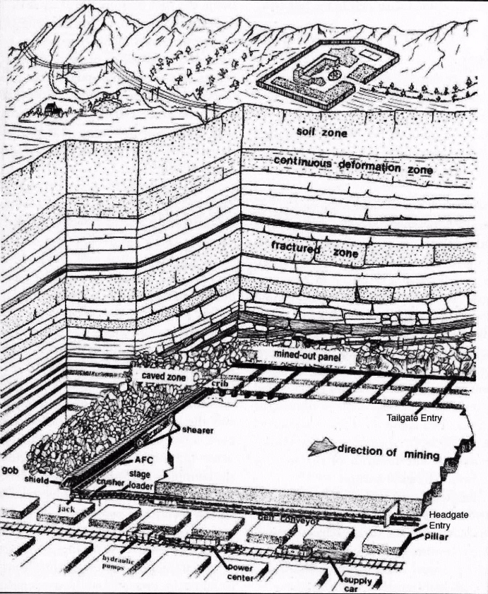
Next, let’s take a look at some videos, each of which is less than five minutes in length. I think these videos are helpful for the details that they show. There are four of them, and they are addressing the same basic topic. However, in each one you can see certain important details more clearly than in the other videos. I suggest that you watch all of them twice, and don’t hesitate to pause them and look more closely at the image. In so doing, you’ll develop a more complete understanding of the equipment and the process.
I want to make one correction to the videos. Caterpillar or CAT as it is known, is a global manufacturer of excellent mining equipment. One important detail of their second video is not quite correct, however. All longwalls in the U.S. use shearers, not plows, including the longwalls operating in thin seams. The reasons for this are not important here, but please remember that shearers, not plows are applied through the U.S coal fields. In MNG 410, we take a more detailed look at longwall mines, including the conditions that favor the use of the plow.
I imagine that you have a reasonable understanding of modern longwall mining after studying the figures and the videos. Allow me to summarize the process and add a few additional details of interest.
Development of the panels is done with the room and pillar method. It generally will take at least two continuous mining sections to develop the longwall panels. From a mine planning perspective, the goal is to ensure that you have panels developed and ready to go. Often, the mine will have spare longwall equipment, and they will partially set up a longwall face on the next panel, so that minimal time will be lost in moving to the next panel and commencing with longwall production. This requires that panel development activities stay far enough ahead of the longwalls to ensure that the next panel can be set up before mining of the previous panel is completed. However, it is important that panel development does not get too far ahead, which would result in developed panels sitting idle for several months. This would represent a poor use of resources, but more importantly, the roof rock often begins to deteriorate when exposed to the moist mine atmosphere. This could result in roof problems before you have begun to mine in those panels.
Services to the longwall face will be placed in the headgate entries. This includes the panel belt, the staged loader and crusher, the hydraulic pumps for the shields, the electrical power centers, the computer control boxes, and the refuge chamber.
The tailgate is under additional roof stresses, and requires additional roof support, such as concrete pillars, timbered crib structures, and so on.
The number of gate roads is typically three, which is a legal requirement in the U.S. Under severe ground pressures, fewer gate entries are advantageous. In the western U.S., a few mines have received special permission to have only two gate roads. Outside of the U.S., you will find single entry gate roads. A reduction in the number of gateroads does create safety hazards that must be managed.
Panel Development
- Develop the gate roads (headgate and tailgate).
- Connect the headgate and tailgate.
- Develop (mine) the setup rooms – the entries connecting the head and tail gate, are mined to specific dimensions and in a pattern to facilitate setting up the long face of equipment.
- Develop (mine) the recovery rooms – once the longwall has been mined, the longwall face of equipment must be moved to the next panel. Given the size of the equipment, additional openings are mined to facilitate the removal of the face equipment. Finish the setup of the equipment on the new panel.
Production Cycle
The basic production cycle is straightforward, as you no doubt saw in the videos. The cutter, whether a plow or shearer, mines along the width of the face. As the cutter moves, the shields advance forward. As they advance forward, the AFC is pushed to the face; and as such, it is ready for the next cut. A few details that are not apparent would include:
- Mining along the face can always be done in the same direction, e.g., headgate to tailgate, which is known as unidirectional cutting, or it can be done in both directions, known as bidirectional cutting.
- Beginning the cutting cycle at either gate is a multi-step process, requiring that the shearer cut into the gateroad, and then gradually cut into the face over a few hundred feet to reach its full cutting depth, returning back to the gate, and then commencing with a full web cut along the full face.
- The shields are lowered to move forward, and when in the new position, the canopy is extended. Usually, the shields will push into the roof momentarily to aid in the formation of a crack in the roof, which facilitates the caving action. The roof typically does not cave immediately after the shield advance, but once caving has begun, the roof will cave reasonably close behind the shields.
Closing Comments
Modern longwall mining systems represent the highest level of technology and engineering achievement in mining method design. The design of the individual components has pushed the envelope on electrical, mechanical, and hydraulic component design. The productivity of these systems is unrivaled, and the raw tonnages achievable per shift are staggering compared to what was state-of-the-art 20 years ago. As cutting technology advances to allow continuous cutting of harder materials, you will see these systems applied in other commodities… but only if what is true?
This brings us to the end of our discussion of the supported and caving classes of underground mining methods.
Module 9: Sustainability
Module 9 Overview
Module 9 Overview
The first lessons of this course focused on the importance of minerals and the role of mining in modern society. The remainder of the lessons in the next seven modules concentrated on the “nuts and bolts” of mining – the five stages that make up the life cycle of a mine and the details of each stage. It only seems fitting then to conclude this course with a module that is concerned with ensuring that mining not only continues to exist in the U.S. but that it co-exists harmoniously with communities and society in general.
It’s an odd situation, isn’t it?
On the one hand, mined products are essential to virtually everything that makes up our standard of living; and as we saw in the first lessons, mining is a major contributor to the economy. While the mining industry employs only a few hundred thousand workers directly, it creates millions of down-stream jobs and contributes billions to the federal, state, and local tax base. So, mining not only provides the minerals essential to every nook and cranny of our lives, but it provides many jobs and societal benefits.
On the other hand, society is largely ignorant of the need for mining and its value, and that which people “know” about mining is generally negative. The commonly held views of mining as an environmentally damaging industry or mining as a dangerous occupation, for example, harken back to an industry of the early 20th century, not the 21st century. Nonetheless, mining activities often bring out vocal critics, and generally, the underlying sentiment is that mining is going to threaten something we care about – peace and quiet, traffic, water quality, the landscape, and so on. And furthermore, these critics would say that we don’t really need mining anyway!!!
These uninformed, but passionately held viewpoints often cause government agencies at all levels to adopt restrictive, and some would say draconian, practices and policies to limit mining activities. Just as a quick example, out of 80 mining countries, the U.S. ranks #78 in the time that it takes to obtain a mining permit! This creates a huge financial burden on companies and drives much investment out of the U.S. to other countries. This extraordinary delay, often exceeding a decade, is a direct result of public resistance to mining and regulatory processes that are easily abused to delay mining projects.
So, why should we care? There are many reasons, but perhaps near the top of the list is our desire to conduct mining operations with societal support over the long term. We, as mining professionals have a significant amount of control over whether or not the industry moves forward in conflict with society or in concert with it. Some would say that we need to take steps to make our industry more sustainable; and as mining engineers, we need to take more responsibility for the current mess and take proactive actions to change the future of the industry. This concept of making the industry more sustainable through our actions is the subject of this module.
In the first lesson, we’ll look at the definition of sustainability and the three dimensions of sustainable development. In the second lesson, we’ll identify the areas in which we need to take action to achieve sustainability. For now, let’s simply state that the three major action areas are: mining practices; community relations; and safety, health, and environment. We’ll look at these in more detail in the coming lessons, and with this as background, we can identify the learning outcomes for this module.
Learning Outcomes
At the successful completion of this module you should be able to:- Define what we mean by sustainable and explain it in terms of the Venn diagram for sustainable development;
- describe the three dimensions of sustainability for the mining industry, and cite examples of issues or questions considered with each dimension;
- identify specific mining practices that impact sustainability, and cite a few examples of how these practices could affect the equitable or bearable regions;
- describe an action plan to manage and improve community relations and public perception of mining;
- explain the effect of safety, health, and environmental performance on the “social license to mine,” and the relationship between this and the equitable and bearable regions;
- explain what is meant by statutory compliance and zero harm.
- explain why leadership, culture, and systems constitute a framework for achieving zero incidents and explain what is meant by each of these terms;
- explain the difference between a hazard and a risk;
- explain the plan-do-check-act actions of a health and safety management system;
- construct a risk assessment matrix;
- conduct a bow tie analysis for a given event, such as a mine explosion;
- describe how the HSMS approach directly applies to environmental performance and use surface water runoff as the example to illustrate the application of the approach.
Lesson 9.1 A Framework for Sustainability
Lesson 9.1 A Framework for Sustainability
Sustainability is one of the words that many people use, but few agree on exactly what it means! The origin of its current use is rooted in a basic reality: the resources of planet are limited, and human activities today should be undertaken in a way that will not disadvantage or otherwise limit the opportunities of future generations.
Many years ago, I was a “guest” at a mining camp in a very rural part of a developing country. Our day started with a hearty breakfast including eggs. The evening meal was varied initially, but the senior member of our group favored chicken and requested that it be served, and each night for the remainder of our stay we had a chicken dish. Our original four-day stay was extended by another three days due to some problems with the project. On our last day, our breakfast did not include any eggs, much to our dismay. At the risk of offending our hosts we politely inquired and learned that there were no eggs because there were no chickens. They had killed off the chickens to prepare the chicken dishes. This is a true story and a good example of a practice that was not sustainable!
When it comes to using resources, many think of sustainable practices as those that consume resources needed by society, but at a rate no greater than that which will ensure the availability of those resources to futures generations so that they may meet their needs. Usually, it is assumed, if not stated explicitly, that the production of these resources is done without harm to the environment. When I think about mining’s need to be sustainable, I think about an industry whose practices are congruent with society’s values. Let’s try to better understand just what that means to the practicing mining professional.
The three dimensions of sustainability are economy, society, and environment; and are represented in Figure 9.1.1, which illustrates that economy and society are constrained by the environment (planet Earth).

A representation that I like even better is shown in Figure 9.1.2. My preference for this representation lies with the two-way intersections that create the bearable, equitable, and viable regions of the diagram; and then of course, the three-way intersection of these to define the sustainable region of the diagram. The bearable, equitable, and viable regions align well with the sustainability challenges associated with mining and minerals recovery, and we will use this model in our discussion.
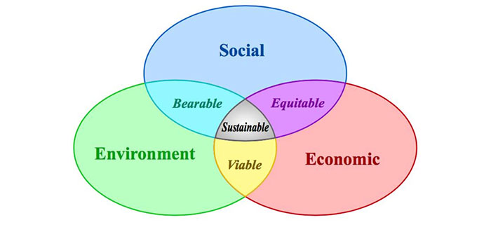
For the purposes of this discussion, I’ll use the word project to represent the mining operation. I will generally use both the future and present tenses in this discussion of the regions in the Venn Diagram. IF we are considering a new project, we will most likely be considering future actions, and the future tense is appropriate in such a discussion. Once the project is underway, our actions are occurring in the present, and consequently the present tense is required. Sustainability considerations must guide our present actions on existing projects as well as how we move forward with proposed projects.
I’ll illuminate through examples what we mean by the terms used in the Venn diagram (Figure 9.1.2). Please note that my examples are not exhaustive, but rather are intended to give you a deeper understanding of each term.
9.1.1 Social - Economic
9.1.1 Social - Economic
First, we’ll illuminate through examples what we mean by social and economic, and then we’ll look at the intersection of the two, which forms the equitable region. Similarly, we’ll use examples to illustrate that which many would consider as equitable. Please note that these examples are not exhaustive, but rather are intended to give you a deeper understanding of each term.
The social dimension of sustainability would consider the following questions.
- Will (does) the project improve the infrastructure of the community, e.g. schools, hospitals, water supply, and highways?
- Will (does) the project contribute to the local economy, through tax revenue for example, in addition to creating jobs, and is this contribution in reasonable proportion to the value obtained by the company?
- Will (does) the project provide good-paying jobs within the local community?
- Will (does) the company provide training and education opportunities to improve the skill sets of workers?
- Will it be necessary to displace or move indigenous peoples as a prerequisite to mining activity?
- What will happen to the community or region when the project is completed? Will there be other industries to employ the workers from the former project?
The economic dimension would consider the following question:
- Is (will) the financial performance1 of the project (be) consistent with investor or company expectations?
This single question captures and represents the sum total of everything that affects the cost of bringing a mineral product to market. It also reflects market conditions, i.e. the price at which we can sell our product and the amount of product that we can sell. However, for this discussion, we will neglect market conditions and instead focus on the cost side of the equation. The mining and processing costs will be based on the many factors that we’ve studied in this course, e.g. ore grade, depth of the deposit, geotechnical characteristics of the orebody, the extent to which mechanization and automation can be applied, and so on. Of special interest here are any expenditures that would be made to address the social dimension of sustainability, such as strengthening the community through the improvement of infrastructure.
The intersection between the social and economic dimensions is aptly named equitable. Are the economic benefits that will accrue to society, and in particular the community, in reasonable proportion to the social costs of the project and to the economic benefits that the company will realize from the project? This is a difficult question to answer – how do you calculate this value? While every situation is likely to be somewhat different, there has to be genuine respect for the community and its institutions, as well as a desire by the company to improve the community within the realistic financial constraints of the project.
Unfortunately, it may become even more complicated. Whether or not a solution will be considered equitable can depend on the ethical framework under which the proposed solution is evaluated. Let’s take a non-mining example to illustrate this. Suppose that it is determined that a dam is needed at a certain location on a major river. The dam will provide flood control, sparing towns along the river from the devasting floods that occur every decade or so. The reservoir created by the dam will provide a more stable source of water for communities, and it will create some recreational opportunities as well. In total, thousands of people will benefit if this dam is built. Those are the “positives.” What about the “negatives”? There are a few dozen houses and farms that will become uninhabitable as the water accumulates behind the dam. In some cases, generations of the same families have lived in this area. The entity proposing the dam, which in this case is a government body rather than a private company, will pay the displaced landowners a substantial premium over full market value for their residences. Nonetheless, some landowners do not want to relocate and are opposing the construction of the dam. What to do...
Has an equitable solution been proposed? On the face of it, it would appear so. The landowners who will be displaced will receive sufficient money to relocate and are getting an additional sum of money for their inconvenience. Indeed, this and similar scenarios play out on a regular basis for infrastructure projects, and this is supported by the utilitarian school of ethical behavior. This school is about the greatest good for the greatest number of people. When viewed through the lens of the utilitarian ethic, the proposed project is ethical and this will strengthen the assessment that the action is equitable as well. Many industrial projects, including mineral projects, have long been evaluated under the utilitarian ethic.
In recent years, however, some have been applying another school of ethical thought known as deontology, which is concerned less with what is “good” and more with what is “right.” This is a school of thought concerned with social justice and the idea that basic human rights supersede what is good for society at large. When viewed through this lens, the dam project is unlikely to be deemed equitable, and as a consequence, there are likely to be protests, government appeals, and other actions to derail or delay the project. For mining projects, we have an obligation to address the parameters of the social and economic dimensions to achieve something that will be deemed equitable when viewed through the lens of the utilitarian ethic, and it is in our best interests to try to understand and address concerns when viewed with the deontological ethic. In essence, the evaluation of the utilitarian school is focused on rightness or wrongness of the consequences of actions, whereas the deontological school is focused on the rightness or wrongness of the actions.
1 Financial performance is assessed through metrics such as net present value (NPV) of the project, discounted cash flow internal rate of return (DCFIRR), payback period, and earnings before interest, taxes, depreciation, and amortization (EBITDA). This will take into account many of the locational, natural and geologic, and socio-political factors discussed in Lesson 4.1.
9.1.2 Social - Environment
9.1.2 Social - Environment
Previously, we looked at a list of questions to help understand the social dimension of sustainability. Now we need to identify relevant questions focused on the environment dimension.
- Will the project adversely affect air or water quality during operations or after the project is completed?
- Will the project create other hazards during operations or after the project is completed?
- Will the project create nuisances, e.g. noxious odors or noise?
- Will the project spoil the landscape, or otherwise reduce the recreational value around the project?
Operating permits, legislation requiring reclamation as well as the Clean Air and Clean Water Acts to protect the air and water quality, guarantee that the environment dimension is well managed... except for the last question in the foregoing list.
The intersection of the social and environment dimensions is identified as bearable. This region represents a solution in which the environmental costs of a project are deemed acceptable when weighed against the social benefits of the project. As with our last discussion of the equitable region, there is no definitive quantification of “bearable,” and as such, it is subject to the interpretation of the parties affected by the project. Consequently, this will likely be interpreted through an ethical lens. The deontological ethic would assert that the environment, including the landscape, its innate beauty, and its enjoyment is a right of everyone; and therefore, regardless of any benefit, no one has the right to impinge on the landscape. Although the surface area of land that is affected by mining is extremely small, it is generally impossible to surface mine without changing the appearance of that parcel of land. It can be reclaimed, and perhaps to even better use than before, but the original appearance is likely to be changed. Indeed, this change in appearance is often an underlying motivator for protests against mining projects.
9.1.3 Environment - Economic
9.1.3 Environment - Economic
We have already identified relevant questions to characterize these two dimensions. A consideration of the intersection, defining the viable region, requires consideration of more specific and technical questions, beyond those already posed. Unlike the considerations of the bearable and equitable regions, the viable region is completely definable by the engineering and science of environmental protection.
We, as engineers, define the engineering steps necessary to protect the environment, in terms of air and water quality, and also in terms of mine closure considerations. Moreover, our reclamation plan can be designed and its costs calculated. Thus, we are able to quantify the costs of protecting the environment. We can even choose to take proactive measures above and beyond those required by any regulations. Of course, that will entail an additional cost, and at some point, the cost of such measures could sink the project. Hence, using the name viable to define the intersection is quite appropriate; and if the cost to protect the environment is too great, the project will no longer be viable.
9.1.4 Sustainable
9.1.4 Sustainable
The intersection of the three regions, bearable, equitable, and viable, defines the sweet spot of sustainability. If you think about it, how could it be anything else? The needs of society for minerals and the needs of the mining company to satisfy the expectations of their shareholders will be balanced against the constraints of the environment and the need to operate in an ethical and socially responsible fashion.
The goal of this discussion has been to equip you with an understanding of the evolving expectations for sustainable development and the ways that society views and evaluates industrial activities such as mining. No doubt you appreciate how difficult it is to establish whether or not something is bearable or equitable, and undoubtedly you can imagine how difficult it could be for a company planning a project over which some are opposed. Despite the uncertainty and fuzzy nature of bearable, equitable, and to a lesser extent viable, there are concrete actions that you can take in the planning and operations stages to facilitate sustainability. We are going to take a look at these in the next Lesson.
Lesson 9.2 You are In-Charge
Lesson 9.2 You are In-Charge
Yes, it is true. You as a mining professional, along with your colleagues, and the companies that constitute the mining industry are more in control of your destiny than many like to admit. Moreover, the industry and its actions, or in some cases lack of action, have contributed to the current poor state-of-affairs for mining throughout the world. For too long, and in too many corners of the globe, mining companies, often with the blessing of local governments, have conducted their business without due regard to societal expectations; and now everyone is paying a price! And, it’s time for that to change! Okay, that felt good... now let me step down from my soapbox.
First of all, it is changing, and positive change is being advanced by leaders in the global mining community with the guidance of their professional and trade associations. However, lasting change, and the leaders of this movement all agree, will only be achieved through the sustained actions of the next generation of mining professionals. Why is this? Unlike your predecessors, you are being equipped with a new set of tools that will allow you to take more informed actions that will pave the way to a more sustainable industry. You see, the work that needs to be done is on an on-going basis, not once and done; further, it cannot be done by only certain designated persons within each operation. Rather everyone has to do their part, every day, and a goal of this lesson is to outline what that means for you.
I’ve chosen to group those actions into three categories, and I list them in no particular order: mining practices; community relations; and safety, health, and environment. And, before proceeding, I should clarify a few points. As with previous lists, the examples that I give here are representative but are by no means exhaustive. The focus of this discussion is on facilitating sustainability and not on traditional mine design and operation – here we are looking for ways to supplement and complement traditional design and operation to become more sustainable. In other words, what is it that we should we be doing in mine planning, design, and operation so that our mining is conducted in harmony with societal expectations?
9.2.1 Mining Practices
9.2.1 Mining Practices
All mining, past and present, has occurred on less than a fraction of a percent of the Earth’s land mass; and the mineral resources mined to date are a small fraction of the total estimated resources. We, as miners, cannot control societal demand for minerals, but we can take steps to ensure that resources are not squandered. We do this through a design and planning process that allows us to achieve the highest extraction rate that is safely possible. In surface mining, we normally have strong economic incentives to recover all of the ore above the cutoff grade. In underground mining we usually need to leave some resource in-place for ground support reasons, and this will limit the extraction ratio. Extraction ratios of 60% are not uncommon, although for some commodities, the ratio will be much higher. Remember that after we have finished mining a specific reserve, it is almost always impossible to go back at a later time to recover additional ore. It is often said that the resource has been “sterilized.” From a sustainability perspective, we want to ensure that we are not wasting the opportunity to recover all the resource than can be recovered safely and economically; and we do this through proper planning and design.
Mines receive permits to operate, and these permits typically define conditions of operation. The constraints imposed by the permits may include operating hours, noise levels, water usage and discharge, and so on. These limitations are generally in addition to regulatory constraints, such as the clean air standards. Regardless, it is in the company’s best interest to ensure that operations are always practiced within permit limitations.
Often mines are located near or in communities, and their appearance from public areas, e.g. roads and residential developments is a concern. The use of landscaped berms to completely shield operations from public view is a good practice, as are attractive and well-maintained entrances to the mine property. Admittedly, there are some large surface mines that cannot be shielded from public view, e.g. Bingham Canyon copper mine These are the exception, and even in those cases, steps should be taken to improve the appearance through increased green areas on the site and better management of waste and product piles.
Blasting practices at surface mines located near communities are always contentious. We’ll talk about this again under community relations, but the design guidance given in Module 6 is critical to minimizing the technical and public relations problems arising from blasting.
Reclamation is of course mandated by various regulations. Often, within the conditions of the regulations and permits, there is some leeway in timing and methods. In addition to the traditional operating considerations affecting reclamation, the view and perception of the public should be factored into the reclamation planning process. Minimizing both the extent of exposed areas and the time that they remain exposed prior to reclamation becomes important if you are concerned about the bearable in addition to the viable region of the sustainability diagram. Even in operations where much of the reclamation cannot occur until near the end of the mine life, e.g. an open pit mine, small actions can be taken to think about the placement of overburden and waste piles for example. It is likely that the placement of these piles will be driven primarily by mine planning concerns, but whenever possible, sustainability considerations, balancing the viable and bearable regions, must be part of the thinking process.
9.2.2 Community Relations
9.2.2 Community Relations
Simply put, if you want to be accepted into a community, you have to behave like a citizen and strive to become part of the community. You can improve your chances of becoming a part of the community if your behavior and actions strengthen the sense of community.
As a starting point, it may be helpful to think about a few realities. First, even if most people recognize that your mine is providing good jobs and contributing to the tax base, they still don’t want you in “their backyard.” We all drive cars, but how many of us want a car factory nearby? We all take comfort in knowing that a hospital is available in our community, but how many of us would be happy if they broke ground for a new hospital down the street from our house? You get the idea! It’s nothing personal against you or even the company, but people don’t want an increase in traffic, a noise source, or an eye sore in their community. They are concerned about their quality of life and the value of their home. Understanding their concerns is a good starting point to help you understand the task that lies ahead and the journey to become a valued member of the community.
While there is no one “magic bullet,” there are actions that many companies have found productive. Here are commonly mentioned ones.
Community Day: Invite your neighbors for a tour of the mine. Once they better understand what you do and how you do it, they are likely to have a better impression. Combine this with a cookout and a social opportunity for the community to meet and talk with the people who work at the mine. Don’t be afraid to share reclamation and mine closure plans, or to answer questions about the operation. Rather than simply complain about public ignorance, accept that it is your responsibility to educate and inform! And of course, recognize that this is something that requires attention year-round, not just during Community Day.
Citizens Advisory Group: If there are concerns and there is an active citizen's group, work with its members to form an advisory group where they can channel their concerns and engage productively with mine management. However, please understand that if you do this, you and your management must engage in good faith. Otherwise you are likely to take a difficult situation and turn it into a very bad one!
Employee Engagement: Encourage employees to be active on the school board, in civic organizations, e.g. Rotary Club or Lion’s Club, in schools as speakers, in coaching of kids' sports, or in the scouts, among others. Adapt employee work schedules insofar as is practicable to facilitate their participation. Donate rock kits or informational literature to the schools. Invite science teachers to visit your operation.
Donate to Local Activities: Sponsor the local youth teams for soccer, baseball, softball, and so on. Buy the team new uniforms. Purchase sponsorships in local civic events. Make a donation to the local library’s annual fundraiser.
In-Kind Contributions: depending on the nature of your mining operation, you may have surface construction equipment, trucks, wheeled loaders, dozers, and so on, and you may have construction aggregates and even concrete and/or blacktop (bituminous concrete). You may be able to donate the equipment, along with operators and materials, to redo the local ballfield, or to put in or extend a local bike path, for example. If you cannot support the entire cost on your own, you might be able to donate just the machine time or perhaps the materials. These efforts can net goodwill for years to come.
Be a Good Neighbor, Every Day: Do not play “fast and loose” with the parameters of your operating permits, and make sure that contractors and customers coming onto your site do the same. If trucks are taking product from your yard, make sure they are covering their beds before leaving the property, and while you are at it, make sure they are not tracking mud or stone dust onto the public road. Undercarriage water sprays are commonly used in some operations. Back-up alarms are often noted as the single greatest aggravation within the community. When MSHA regulations allow, consider using strobes instead of audible alarms.
You can look at these community relations activities as a major investment in the equitable region of the sustainability diagram. And remember, it’s not about how much money you spend, it’s about making a genuine effort to strengthen the institutions and organizations that comprise the community through your company’s involvement.
9.2.3 Safety, Health, and Environment
9.2.3 Safety, Health, and Environment
There were four mine explosions in the U.S. in the first decade of this century, including one that was the worst such explosion in the past 40 years. Globally, there several high-profile mine disasters from New Zealand to China to Brazil, and many other countries in between. Although the number of fatalities in each of these was far less than in many other disasters, the public has a much lower tolerance for a mine fatality than other disasters. A typical response to the news headlines by the average person on the street was ‘this is terrible, why do we need to mine, why should we be putting these people at risk?’ And as you might expect, these events provoked strong legislative responses across the globe, resulting in not only legislation for improvements, but in some cases, a substantial over response.
As this played out, the U.S. industry in particular, but the global industry as well, realized that they needed to be more proactive. They realized that it was not sufficient to merely comply with regulations. They needed to take additional steps to eliminate: major safety hazards, e.g. a mine explosion, that result in multiple fatalities; major health hazards, e.g. silica dust, that result in debilitating occupational diseases; and major hazards, e.g. tailing dam failure, that result in environmental disasters. During this period there was every reason to believe that one more high-profile disaster would result in the mining industry losing its “social license” to mine. In other words, the public, and by extension their legislators, would decide that ‘enough-is-enough and we’re going to ban this activity regardless of its other benefits.’ The industry was duly alarmed and knew they had to take action to eliminate these disasters2.
The focus of this discussion is not the general topics of safety, health, and environment, how we apply our engineering and science skills to achieve safe and healthful workplaces, and do so in an environmentally responsible fashion, but rather on the management of safety, health, and environmental activities to help eliminate mining disasters. We, as industry in general and mining in particular, have been complying with regulations for decades, and yet every year workers die and environmental accidents occur. Safety and health were the focal points of the conversation, and the turning point was the report published by the National Commission for Mine Safety, Technology, and Training. This report advocated a more aggressive and proactive approach to mine safety, and the CEOs of the major mining companies signed a pledge committing to take the steps necessary to eliminate fatalities and reduce injuries. Mitigating environmental risks was not addressed at that time. However, the methodology to achieve this concept of zero harm3 in safety and health can be applied directly to the environment scenario as well. In the next lesson, we’ll introduce this methodology.
2In the U.S., a mining accident in which three or more persons are killed is designated as a disaster. This number is determined by MSHA and the number sometimes changes over different presidential administrations.
3 This implies that the activity should be conducted in a way that results in zero harm to the mineworker's safety or health. The concept is directly applicable to the environment as well, indicating that the activity should result in no permanent harm or damage to the environment.
Lesson 9.3 A Sustainable Approach to Mine Safety and Health
Lesson 9.3 A Sustainable Approach to Mine Safety and Health
We studied mining laws in Lesson 2.2, and you learned that various laws affecting mining form the basis for regulations that are administered and enforced by federal and state agencies. The act of following, i.e. complying with, the regulations is known as compliance. If you do not strictly follow the regulations, your company can be penalized, i.e. given a citation. These penalties can range from a few tens of dollars to hundreds of thousands of dollars, and can include temporary closure of the mine until the citation is corrected. In a few instances criminal charges can be brought against mining company officials in addition to civil penalties. The procedures for interpreting and enforcing the regulations, as well as the calculation of the penalties, is beyond the scope of this course4.
If you examine different types of regulations across many industries, you will find that they are generally performance-based regulations. A performance-based regulation specifies the desired outcome and leaves the means of achieving that outcome to you. A prescriptive regulation, on the other hand, not only specifies the desired outcome but directs you to achieve that outcome in a specific, i.e. prescribed, fashion. Many mining safety and health regulations are prescriptive in nature. There are a limited number of cases where a prescriptive regulation is warranted, but in many cases, it is problematic; and the biggest problem is that it unwittingly transfers responsibility from the mine operator to the enforcement agency (MSHA)!
Historically, many operators held the belief that because MSHA told them how to comply with the regulations and because MSHA inspected their operations for compliance, they were absolved of any responsibility for adverse safety and health outcomes... as long as they complied with the regulations. MSHA requires the companies to prepare detailed plans on topics such as ventilation and ground control, and the company is not allowed to operate until MSHA has agreed to their plan and approved it! It is no surprise that operators took the view that their responsibility was to comply with MSHA’s requirements and that MSHA was ultimately responsible for the safety of miners.
It became clear after the U.S. mine disasters in 2006 that a system focused solely on compliance was not achieving the desired outcome. Moreover, that was a contrasting approach in another great mining country, Australia. While the tipping point for the U.S. was the Sago Mine disaster in 2006, the Australians had theirs in 1994 with the Moura Mine disaster, and over the ensuing years, they developed and institutionalized a very different approach to achieving safe and healthful workplaces, which could be characterized as a risk-based approach, and by 2006, their system was producing remarkably better outcomes.
An analysis of fatalities over the decades reveals that root causes are not simply engineering failures, but are often a combination of cultural, leadership, and systems failures. The approach that was adapted for U.S. mining was based on the Australian successes as well as similar approaches used in other industries where low probability but high consequence events cannot be tolerated (think nuclear power plant). The U.S. National Mining Association, took these successful approaches and adapted them for the U.S. industry; and then developed implementation materials and training to facilitate the diffusion of this approach through the industry. Their approach is known as CoreSafety.
4 If you are interested, I would recommend taking a quick look at three sources: Subchapter P of 30 CFR, which describes the calculation of civil penalties, Section 104 through 110 of the Federal Mine safety and Health Act, which describes penalties and processes including orders for mine closure, and The Mine Inspectors Manuals, which provides detailed guidance on how to interpret certain regulations and how to select the level of penalty that is to be assessed for a specific violation of a mandatory safety or health standard. You can access all of these through the MSHA website.
9.3.1 CoreSafety
9.3.1 CoreSafety
This discussion and the figures included in Lesson 9.3.1 are abstracted from National Mining Association materials on CoreSafety and are reproduced here with permission.

Leadership is essential in affecting the behavior of workers. Safety and health performance is directly enabled (or hindered) by the behaviors and decisions of company leaders. Leaders have a responsibility for ensuring safety is integrated into all aspects of the business, holding people accountable for their responsibilities, driving a safe culture, having effective safety systems, and setting a safe example, among many others.
Many organizations that have realized substantial performance improvement have identified leadership development as the catalyst for that change. Leadership development is the process of identifying critical leadership competencies and providing structured development opportunities for leaders to improve those competencies.
While there are many leadership competencies that are complimentary to safety and health management, NMA has identified eight that are critical in the U.S. mining industry. These competencies include, but are not limited to:
- managing by objective using structured accountability;
- understanding and influencing culture;
- leveraging communication and collaboration;
- having credibility and integrity;
- using performance feedback and management;
- being action-oriented; and
- and understanding management systems and ensuring they work as designed.
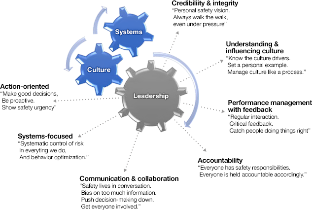
Safety culture can be defined as a pattern of behavior that is encouraged or discouraged by people and by systems over time. This is a very important concept – think about what it means! Do we have a culture that values safety over production? Does the “system” reward us or penalize us if we bring safety concerns to the attention of management? Do we have established committees to look for opportunities to improve safety? We could go on with another fifty questions, but I think you are getting the idea.
Culture determines what we do when no one is watching! This statement makes it clear: if we don’t have a good safety culture, we will be unable to achieve good safety performance. The attributes of a good safety culture are illustrated in Figure 9.3.3.
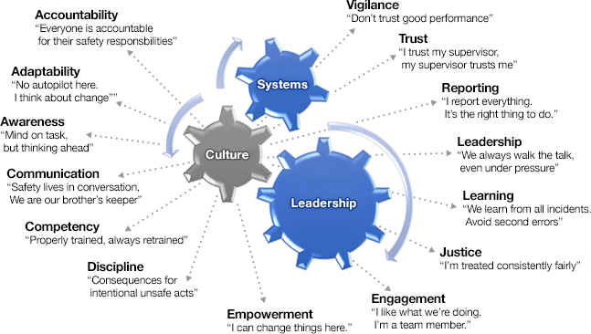
The systems element of the zero-incident framework shown in Figure 9.3.1 represents those processes and systems used to identify and address hazards. All of these are captured nicely in one overarching system known as the HSMS, i.e. the Health and Safety Management System. Often the order of health and safety is changed, so you are equally likely to see SHMS, i.e. Safety and Health Management System. The content and function of the HSMS is defined by a standard such as the American ANSI Z10 or the Australian OHSAS 18000. CoreSafety encompasses the best of these standards. An effective HSMS will facilitate an orderly and systematic identification of hazards and the development of solutions to mitigate or eliminate risk associated with these hazards. Further, the system will facilitate the verification that the solution was effective and will incorporate regular audits to ensure that risks are managed. The flow of an effective HSMS system is illustrated in Figure 9.3.4.
After decades of experience we know that prescriptive regulations are nominally effective, systematic control of risk offers the best opportunity to eliminate fatalities, leadership plays a critical part of improving safety performance, leadership drives culture, and culture affects systems. Figure 9.3.1 illustrates this relationship.The integration and active management of systems, culture, and leadership can produce world-class performance. Let’s look at each of these elements in a bit more detail.
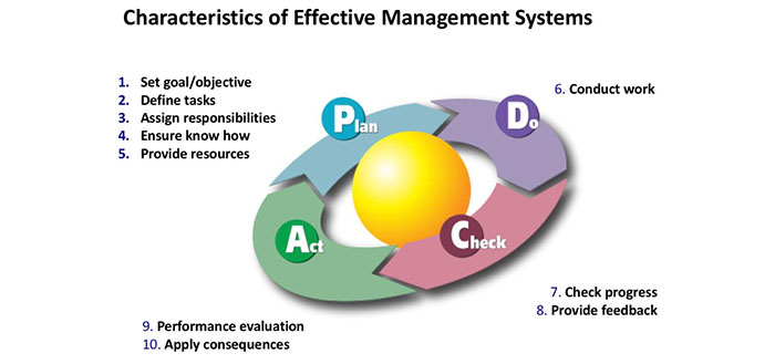
The circular nature of this diagram draws attention to the need for an ongoing process. Before moving on, a few additional comments are in order.
The Plan phase encompasses five activities:
- Set goals: all risks in all the company’s operations cannot be addressed at once... it is necessary to divide the work into achievable chunks.
- Define tasks: identify the task that will have to be completed. Example tasks could include conducting a site survey, reviewing past accident records, performing engineering calculations, designing risk mitigation measures, purchasing materials or hiring consultants, and installing interventions.
- Assign responsibilities: Clearly identify who is responsible for doing a task AND who will be accountable for the completion of the task. This is one of the points at which the HSMS fails because it wasn’t clear who was doing what, and then things “fall through the cracks.”
- Ensure know how: make sure the people assigned tasks have the knowledge and skills to complete the task. Although this sounds obvious, it is another common failure point within the HSMS.
- Provide resources: It usually requires time and money to implement the actions identified in the Planning Phase. Usually the money is allocated, but often the time is not. Suppose I want to implement a series of tasks for the Bedrock Quarry, and I assign responsibility for conducting the risk assessment to my quarry manager, a task that may take a few weeks to complete. I know that my quarry manager, a Penn State grad, is proficient in conducting risk analyses. Most likely I have set up a failure at this point! Why? The quarry manager has a full-time job, from 6 in the morning until 6 in the evening running the quarry. When will she find time to do risk analyses? She won’t. You have to allocate the resource of time if you want to be successful. Maybe we bring in an assistant quarry manager form another operation for a few weeks or find another solution.
Having completed the planning phase, we are ready to spring into action!
The Do Phase is when we conduct the work. This work could include a variety of solutions including developing an offering training, changing certain work practices, installing engineering controls, implementing different operating procedures, and so on.
The Check Phase is too easily forgotten. We identify a problem, craft a solution, and assign people to implement the solution. That’s that! We’re done! Right? Well, not so fast! Things come up, people get distracted by other tasks, and sometimes an unforeseen problem arises, which prevents full implementation of the solution. The bottom line is that someone needs to check to ensure that the solution was implemented and to provide feedback to the people responsible for the planning and doing.
Finally, there is the Act Phase. Based on our planning, doing, and checking, we have the expectation that we’ve successfully eliminated hazards and managed risks. That’s a reasonable belief to have, but it is a belief that needs to be tested. How do we “test” our belief? We assess the effectiveness of the solution. It may be something that we can visually assess through an inspection, or other instances we may be able to look at data to see whether or not a certain category of injury has decreased. Regardless, conducting audits must be a regular occurrence. Although it goes without saying that the findings of the audit must be acted on in a timely fashion, this is another potential failure point. In addition to the performance evaluations that are conducted as part of the Plan-Do-Check-Act process, progressive companies will conduct annual audits of their mines – and here’s the clever part – these audits will be conducted by the manager of a different plant or mine within the company! Nothing like a fresh pair of eyes to spot potential issues.
There is one very important piece to this brief introduction that I want to cover. Think back to the Planning phase. How do we identify risks and prioritize our work for the Plan-Do-Check-Act cycle? That is the missing piece that needs to be covered, and we’ll do that in the next lesson.
Lesson 9.4 Risk Management
Lesson 9.4 Risk Management
Life is fraught with hazards. At the moment we are concerned with hazards in the workplace, e.g. the mine or the plant. What do we mean by hazard? A hazard is a situation that presents with a likelihood of adverse consequences. A weak and unsupported roof represents a ground fall hazard, accumulated rock on the walkway next to a conveyor represents a tripping hazard, and a cutting operation in a dimension stone plant represents a respirable dust hazard.
We talk about risk, but what do we mean when we use this term? Risk is a situation involving the chance of loss or injury. On the face of it, there seems to be little difference between the definition of a hazard and a risk. However, there is a subtle but important difference. Risk is taking into account how likely it is that a loss will occur. The weak roof mentioned earlier presents a hazard because it could collapse, and if someone is underneath that spot when the fall occurs, something bad will happen to that person. Whether or not this represents a risk depends on whether or not a collapse is likely to affect anyone. If it is in a remote area of the mine where no one works or travels, the risk is minimal. If it is in the main travel way into the mine, the risk is huge.
It is useful to talk about risk factors as part of this discussion as well. Risk factors are conditions or behaviors that increase the chance of loss or injury. As an example, consider accidents involving surface haul trucks. What are some of the risk factors that could individually or in combination increase the likelihood of an accident? Poor visibility (night time or foggy conditions), deterioration of the berms, operator impairment (drugs or alcohol), operator fatigue, equipment malfunction, and so on. The value of identifying the risk factors will become apparent shortly.
Risk is an inevitable part of our lives at work and play. The challenge is to reduce the likelihood that a risk will lead to a loss or injury, and we meet this challenge by managing the risks. Risk management first requires that we identify the risks. Then if practicable, we work to eliminate them, and failing that we endeavor to mitigate the risks. Elimination while most desirable is often not possible. Think about the risk associated with crossing a busy street. We can’t eliminate the traffic, but if we could build a pedestrian bridge over the street we would effectively eliminate the hazard posed by the traffic. Unfortunately, there are few instances where building such a bridge is practicable. Thus, we will need to mitigate the risk. We might do this using engineering controls such as putting in a traffic light with a pedestrian signal. We might also use a behavioral intervention, where we train everyone who will cross a street to look both ways before stepping off the curb, or we might also employ an administrative control where we have a policy that no one is allowed to cross the street except at intersections. These actions 6 to mitigate the risk will significantly reduce the likelihood of a pedestrian being killed while crossing the busy street. Despite our best efforts, however, a small amount of risk still exists. Indeed, this is the norm, and we ultimately accept some level of risk in our lives whether it is flying in an airplane, investing in the stock market, or eating too many sweets. The challenge is to know when we have reduced the risk as low as reasonably achievable.
The process of identifying risks, risk factors, and the options for mitigating the risk need not be performed in an ad hoc or casual manner. There are many well developed methods for analyzing risk, and each has its advantages depending on the application. There are two simple but powerful tools for analyzing mining risks.
The first is the so-called risk assessment matrix, and it is based on the principle that risk is a function of the probability of occurrence and the severity of the consequence if the event occurs. You can think of it as risk being equal to the product of this probability and consequence metrics. However, to be clear, for mining applications this is a qualitative assessment because we generally do not have quantitative knowledge of either the probability of occurrence or the severity of the consequence. Generally, we do have a qualitative understanding, and that makes this assessment matrix very useful to prioritize our risk management activities. Let’s take a look at Figure 9.4.1.
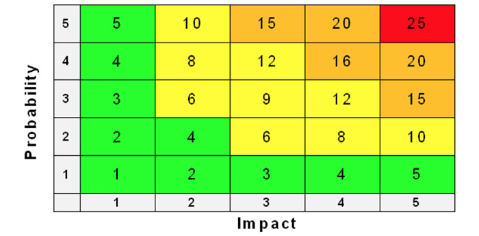
The rows are a measure of probability of occurrence and the columns represent the impact or severity of the consequence. The likelihood of occurrence begins with a “1” at the bottom row and increases to a “5” at the top row, in which the probability of the event occurring increases as we move from the bottom to the top row. Similarly, the impact of the occurrence begins with a “1”, representing the least impact, at the left-most column and ends with a “5” designating the greatest impact at the far-right column. The numbers in the cells represent the risk as the product of probability and impact. The larger the number, the more serious the risk. In this figure the colors have been added to underscore the severity of the risk with green representing minimal risk and red representing extreme risk.
You are probably wondering, how to assign the probability and impact score to a specific event. In most cases, we use a qualitative scale. As long as we are consistent in using the same scale, we can compare and assess the many risks that might be present at our mine. As an example, we might standardize on the follow scale of 1 to 5, where 1 represents the lowest level of probability or impact, and 5 represents the highest level:
| Probability | Impact | |
|---|---|---|
| 1 | very unlikely to ever happen | no injury or insignificant operational cost |
| 2 | unlikely, but such events have occurred | minor injuries or minor operational costs |
| 3 | likely, not common by does occur | significant injuries, operation costs |
| 4 | likely, these have occurred here | severe injury, likely fatality, significant costs |
| 5 | highly likely, they occur from time-to-time | multiple fatalities, major operational costs |
Another very useful tool for mining risk management is bowtie analysis (BTA). This tool combines in one diagram causes and consequences as well as control and recovery measures. A bowtie is illustrated in Figure 9.4.2. The center of the bowtie represents the event, e.g. haul truck accident, a mine explosion, or a conveyor belt fire. The potential causes of the event are placed on the left side of the bowtie, and the consequences of the event are placed on the right side. Dashed lines connect the causes with the event and the consequences with the event as shown.
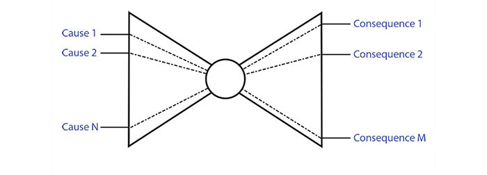
_explosive.jpg)
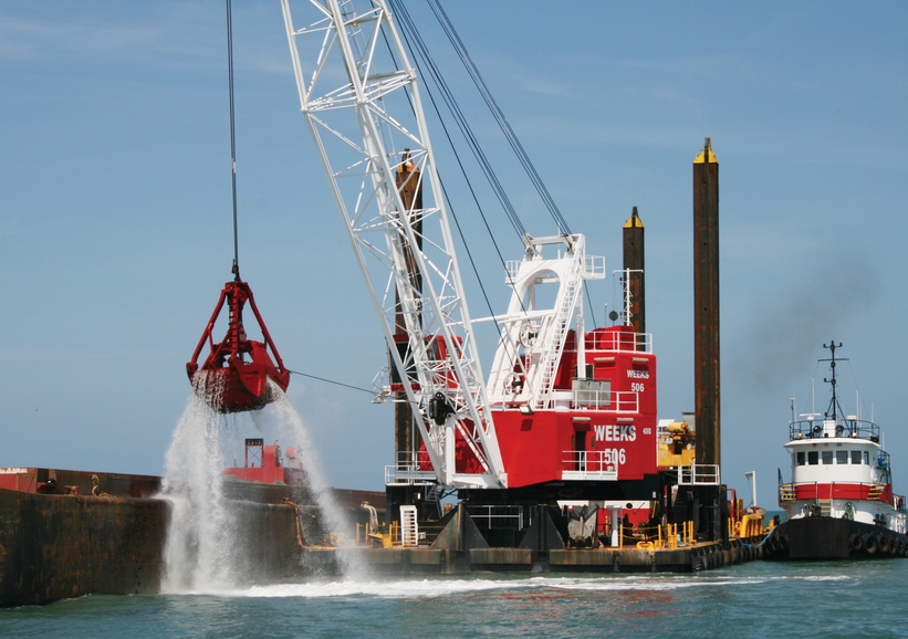
On the left half of the bowtie we will place “barriers” along the dashed lines. These barriers represent actions that we can take to prevent the cause from leading to the event. On the right half of the bow we will again place “barriers” along the dashed lines. These barriers represent actions that we can take to lessen the impact of the event or even to prevent certain consequences from occurring.
Let’s look at an example, and for this example, let’s choose a mine explosion as the event of interest, and we’ll keep it simple to illustrate the concept. First, let’s identify causes that lead up to a mine explosion, and similarly, let’s identify the consequences of the event, i.e. the mine explosion.
Causes of this event are:
- Explosive concentration of methane
- Ignition source
The consequences of an explosion are:
- Miners die from breathing toxic levels of carbon monoxide
- Fire
- Miners in immediate proximity to the explosion are killed by the force of the explosion
- Miners die while attempting to escape from the mine
Next, we’ll want to identify control and recovery measures. A control measure for preventing an explosive concentration of methane is adequate ventilation. A control measure to prevent an ignition source is to use only electrical equipment that is certified as permissible for use in explosive environments. Another control is to equip the machines with methane monitors, which will cause them to shut off if elevated levels of methane are detected.
Providing self-contained self-rescuers (SCSRs) is a recovery measure that virtually eliminates the outcome of dying from CO poisoning. Miners in the immediate vicinity of an explosion will be killed by the air pressure blast, and there are no known controls to change this outcome. Providing quarterly training to miners on self-escape will improve their chances of safety exiting the mine. If they have access to functioning wireless communications equipment to allow communication with the outside world, their chances of safely exiting the mine are improved.
Certainly, we can identify additional root causes, outcomes, control measures, and recovery measures. However, the ones that we have chosen to list here illustrate the technique. The bowtie shown in Figure 9.4.3 is populated with this information that we identified.
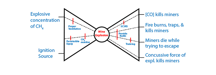
As you look at this bowtie, and the lists that we just made, you may be wondering what useful purpose is served by completing the drawing of the bowtie, rather than working from the lists. In relatively simple and straightforward cases like the one we completed for this example, the only purpose served is a graphic for others to examine and discuss. In more complicated cases, and cases in which all controls or recovery measures are not yet identified, the diagram does serve as a useful tool to facilitate the process. This is especially true if there are interactions between certain controls or recovery measures that need to be identified and taken into account. A more general representation of the bowtie is shown in Figure 9.4.4.
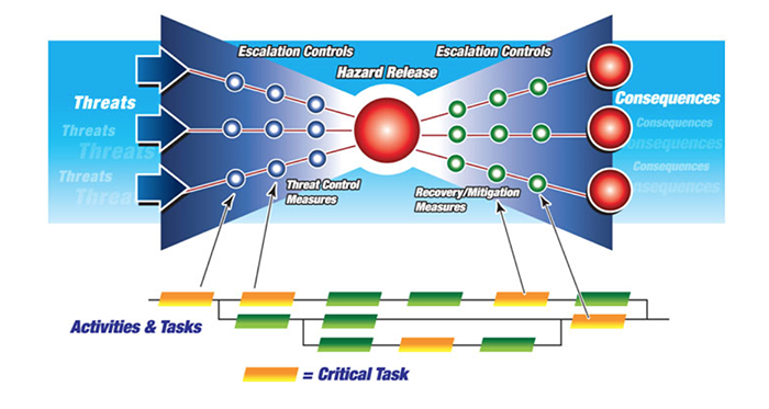
I’ve deliberately used different terms on this bowtie from those I used in my example. Many of these words are used interchangeably, and it is good to be aware of this. Threats and causes are substantially the same, as are consequences and outcomes. The hazard release is the event. The control measures and recovery measures represented on this figure are similar to the nomenclature that I used earlier. No doubt you noticed the addition of a critical path diagram at the bottom of the bowtie. This is not an essential part of bowtie analysis, but its addition to the graphic is a powerful complement to bowtie analysis and this further enhances the planning stage of risk management.
As I mentioned earlier, there are a couple dozen different tools available to do a risk analysis, but only a few lend themselves to the qualitative scenarios encountered in the majority of mining applications. In addition to the risk assessment matrix and bowtie analysis, job hazard analysis (JHA) and workplace risk assessment and control (WRAC) are commonly employed. JHA is particularly useful for studying specific jobs or tasks such as operating a haul truck or changing the bits on a cutting drum. WRAC is a useful tool to conduct a preliminary assessment of risk, but many who do this prefer to use bowtie analysis instead.
6The hierarchy of controls, going from the most to least reliable and effective is: engineering controls, administrative controls, and the use of personal protective equipment (PPE). PPE was not used in this example because it wasn't applicable. Examples of PPE would include respirators to limit dust exposure, earplugs to limit noise exposure, and safety glasses to reduce the chance of eye injury from foreign objects. Simplistically, the effectiveness of engineering controls at the top of hierarchy do not depend on people to mitigate the risk, whereas the bottom of the hierarchy, PPE, will be effective only if people remember to use it and use it correctly.
9.4.1 Application to an Environmental Problem
9.4.1 Application to an Environmental Problem
Compliance with environmental regulations is an important part of the job nearly every day, and especially at surface mining sites. As with safety and health, mere compliance with the regulations is not sufficient if you are thinking in terms of sustainable development. All of the guidance given in this lesson applies to environmental as well as safety and health considerations. To illustrate this, let’s “talk through” a risk management problem related to protecting the environment, and you will soon see that the process is the same regardless of whether we are examining a safety, health, or environmental risk.
The Bedrock Quarry is located in a rural valley with no close neighbors. One neighbor of note is a large state-operated fish hatchery, which sits a few miles from the quarry. This is of note because the quarry discharges several hundred thousand gallons of water per day, and this discharge feeds into the stream feeding the hatchery. Interestingly, the fish hatchery loves the mining operation because the water they discharge is of higher quality than the normal stream water! It’s not often that a mine has a neighbor who loves them! Of course, there is a potential downside to this scenario: if the mine’s discharge should be contaminated, it could wipe out the entire hatchery. Think about the ensuing public relations disaster!
This is the kind of problem that you would tackle with your risk management tools. It is understood that you are operating with an EPA approved storm water pollution prevention plan (SWPPP), and as part of this plan, your company will have identified the day-to-day activities required to remain in compliance with the requirements of the Clean Water Act. Here we are not talking about redoing this plan or setting it aside. Instead we are going to take a fresh look to determine if we are doing everything that we reasonably can to protect the water supply. Remember, compliance alone may not be sufficient to prevent a mishap, and if we are truly mindful of staying within the bearable and viable regions of the sustainability diagram, we need to go above and beyond compliance!
As the first step of any risk management exercise, we need to put together a team. The team should include people with unique knowledge to contribute to the process, and at a minimum should include someone from operations management, an engineer, a safety or environmental staffer, and one or more miners. With the team duly constituted, there are some steps to be taken to help the individuals on the team to function as a team. These are beyond the scope of this discussion, but please realize that you can’t throw five people together, call them a team, and expect that they will function successfully as a team!
The Plan-Do-Check-Act paradigm, which was illustrated in Figure 9.3.4, provides a good road map for the team. As part of the planning, the team will define the objective, which is to ensure that the discharge water is always pure; and then they will define the tasks they believe need to be completed. The tasks will include reviewing the existing SWPPP, auditing the quarry’s performance under the existing plan, conducting a site assessment, performing a risk analysis and a risk mitigation/elimination study. The site assessment will involve several subtasks. Assignments for completing these tasks should be made and a schedule adopted. The person(s) accountable for completion of the tasks should be identified. Once these tasks have been completed, the risk management study can be conducted. The risk assessment matrix can be used to prioritize the risks that will be investigated, and then BTA or another tool of the team’s choosing, can be used to identify needed controls and recovery measures.
Once the controls and recovery measures have been identified, they need to be evaluated for practicality. Some of these may require design and construction, such as swales and rip rap lined ditches. Others may require adoption of operating procedures, such as regular inspections of fuel storage tanks and the prompt use of sorbents in the maintenance shop to cleanup spills. The monitoring and sampling program may require modifications. The “Do” stage of the paradigm, i.e. implementing the findings from the planning phase can be substantial, involving multiple personnel and requiring a period of time and significant resources to implement. This must be carefully scheduled and resourced.
All of the effort expended to reach the end of the “Do” stage will be wasted if a formal effort to verify that the risk management measures have been implemented. Moreover, the controls as implemented should be assessed to determine whether or not they are performing as expected. Of course, if the “Check” stage reveals gaps or shortcomings, they must be acted upon. This “Act” stage should not be treated as an afterthought; rather, the need to “close the loop” must be anticipated and built into the team’s charge. Adequate resources must be provided for this stage as well.
While the primary purpose of this environmental example was to illustrate the applicability of the management system approach, it should be noted for completeness that the Plan-Do-Check-Act paradigm is really an ongoing process, and the next key action would be to perform regular audits, as mentioned earlier.
Module 9 Summary
Module 9 Summary
The primary goal of this module was to tackle the question: what does it mean, in practical terms, to operate in a sustainable manner? We concentrated on gaining a better understanding of sustainability in Lesson 1. We looked at a Venn diagram of the three dimensions of sustainable development, social, environment, and economic; and we focused on the intersection of these three regions, which are known as bearable, equitable, and viable. And of course, it is the intersection of these three that constitute sustainable. From the perspective of a practicing mining professional, the question then becomes: what is it that we do or do not do to make something more or less bearable, equitable, and viable?
We saw that it is difficult to quantify the bearable and equitable regions, but we identified a series of questions to help define how society will view the extent to which the project is likely to be considered bearable and equitable. Making a determination within the viable region is a bit easier because we can quantify the majority of the costs and perform a financial analysis. During our discussion of the equitable region, we encountered two prevalent but very different schools of ethical thought: the utilitarian school and the deontological school. Although civil and industrial projects are most often viewed through the lens of the utilitarian school of ethics, there has been an increase in protests raised by those who subscribe to the deontological school. Armed with a better understanding of what is meant by sustainable, we then tackled the next question: what is it that we can do to improve the sustainability of a mining project?
We began Lesson 9.2 with the premise that there is much that you can do to improve the sustainability of mining, even though historically, our industry failed to be as progressive and proactive as it should have been. I grouped the many actions that could be taken to improve sustainability into three categories: mining practices, community relations, and safety, health, & environment. We looked at examples within the groups of mining practices and community relations. Then I described background on the third group titled safety, health, & environment. The concept of a social license to mine was introduced, and a couple of high profile disasters were cited as examples of the importance of the equitable and bearable regions. The concept of zero harm was mentioned, and the need for a specific methodology to achieve zero harm was identified.
The focus of Lesson 9.3 was an approach to achieve zero harm in safety, health, and environment. Early on the distinction was made between compliance with regulations and achieving zero harm. The difference between prescriptive and performance-based regulations was explained, and the Australian risk-based approach was mentioned. It was noted that an analysis of fatalities and disabling injuries revealed that engineering failures were often not the root cause or the only root cause of the incident. Instead, it was frequently a combination of cultural, leadership, and systems failures.
The method or approach known as CoreSafety is designed to address this combination of systems, culture, and leadership. Each of these was defined and described. Next, the characteristics of effective management systems were identified and the Plan-Do-Check-Act paradigm was introduced. Although somewhat simplistic, this is a powerful paradigm, which forms the basis of CoreSafety as well as the ANSI and OHSAS standards for health and safety management systems. Notably, this exact approach can be used for environmental and other technical applications beyond safety and health. An environmental example of this paradigm was presented at the end of Lesson 9.4.
The identification, analysis, and mitigation of risks are a critical part of the Plan-Do-Check-Act paradigm. Collectively these steps are known as risk management, and this was the subject of Lesson 9.4. At the beginning of this lesson, I defined hazard, risk, and risk factors, and then went on to discuss what is meant by managing risk. The difference between eliminating and mitigating a risk was noted, as were the use of engineering controls, administrative controls, and personal protective equipment. Behavioral interventions, typically training, were noted as another effective way to manage risk. The idea of a hierarchy of controls was introduced.
An effort to identify the risks in an operation may result in a large and rather daunting number of risks. We saw that we can use the risk assessment matrix to develop a risk score based on the likelihood or probability of the hazard occurring and the severity or impact of consequences if the hazard occurs. The identified risks can be ranked according to this score, and then the greater risks should be addressed earliest in the process.
Once we have identified a potential event, in which a hazard is released, we would analyze it to define the root causes and to identify both control measures and recovery measures. We saw that the bow tie analysis (BTA) is nicely suited to the qualitative risks often encountered in our application. After the BTA has been completed, we would assess the practicality of employing various control and recovery measures to mitigate the risk. At this stage, we would be ready to move into the “Do” stage of the paradigm, and we have a basic understanding of what that means. Similarly, we understand why the “Check” and “Act” stages are so important to the overall process.
Many books have been written and entire courses devoted to each of the topics covered in this module, ranging from sustainability through risk management. Some of you may have already taken or will be taking such courses; and for everyone else, this material will serve not only as a platform on which you can base more detailed study but also it gives you knowledge that will be useful in the workplace.