Geocoding
Geocoding is the process of taking the description of a specific location and converting it into a set of coordinates or a point feature which can then be displayed on a map or used in some type of spatial analysis. A variety of location description types can be geocoded including addresses and place names. There are a number of different approaches which can be used for geocoding, but at a high level they all follow the same process:
- Descriptions of the locations to be geocoded are compiled into a standard format.
- The location descriptions are compared to a reference dataset.
- Candidate locations are established and scored according to a set of rules.
- If the score for a candidate location exceeds a threshold value, it is declared a match.
- If no candidate location score exceeds the established threshold, the location of interest is flagged as unmatched.
- If two or more candidate locations share the same score and that score exceeds the threshold value, a tie is declared.
Geocoding is a widely used geospatial technique that has applications across many industries. It is often a prerequisite process to performing some type of network analysis such as routing. There are a variety of distinct processes which can be used for geocoding. The primary differences lie in the type of reference data which is used. The most common type of geocoding uses roadway centerline data where each street segment has address range attributes for each side of the street. Most online geocoding services, including Google Maps, Yahoo Maps, and MapQuest, rely almost exclusively on this type of geocoding. Other types of geocoding use parcel boundary data or address point data. You’ll read more about the different types of geocoding in Assignment 3-1.
There are many geocoding services which are available, some of which are free and some of which are subscription-based. The free services generally limit the number of locations you can process at one time. Given a suitable reference dataset, it is also possible to create your own geocoding service. You’ll have an opportunity to do just that in Assignment 3-2.
ArcGIS Address Locators
The first step to geocoding in ArcGIS is selecting an address locator which will be used. The address locator defines the reference dataset and the rules which will be used by the geocoding engine in identifying candidates and matches for the location descriptions (typically addresses) you are trying to locate. You can use an existing address locator, which typically requires a subscription, or you can create your own. To create your own address locator, you need to have access to a suitable set of reference data. There are many potential reference datasets available including those which are created by state or county governments. One good source of reference data for geocoding is the TIGER/Line shapefiles we examined in Lesson 2.
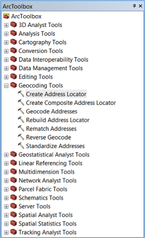
To create an address locator, use the “Create Address Locator” tool in ArcToolbox (see Figure 3.1).
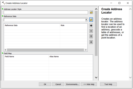
When you launch the tool, you are presented with the Address Locator dialog (see Figure 3.2).
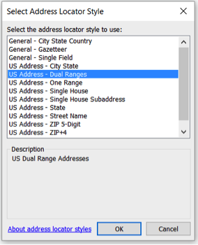
The first step in creating an address locator is selecting a locator style. The locator style which is most appropriate depends on the reference data you’re planning to use in addition to the format of the locations you’re trying to geocode. A commonly used address locator style is the U.S. Addresses – Dual Ranges (see Figure 3.3).
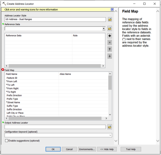
Once the locator style has been selected, the Field Map list in the bottom portion of the Address Locator dialog is automatically populated (see Figure 3.4). Fields with an asterisk are required by the locator style, and fields without an asterisk are optional. Once you have loaded a reference dataset, you can map these fields to the corresponding fields in the reference data.
The second step in creating an address locator is defining the reference dataset or datasets which will be used. As mentioned above, there are many reference data sources which can be used. For example, you can use a linear feature class based on roadway centerlines such as the “Address Range-Feature Shapefile” TIGER/Line shapefiles we reviewed in Lesson 2. Alternatively, you could use a polygon feature class based on parcel boundaries or zip code boundaries. Yet another option would be to use a point feature class based on address points.
Once you have selected the reference data, you can map the fields associated with the address locator style you have selected with the corresponding fields in the reference data (see Figure 3.5).
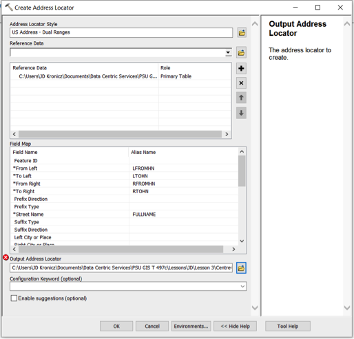
The final step is to save the address locator to a location you select. While you can store the locator in either a geodatabase or a file folder, ESRI recommends storing an address locator in a file folder for better performance.
Here is a link to an ESRI webpage where you can download a white paper which tells you everything you’d ever want to know about address locators in ArcGIS.
Geocoding a List of Addresses (or other location descriptions)
To geocode a list of addresses, you should first add the table of addresses data to your map document in ArcGIS. The addresses to be geocoded can be prepared in any number of file formats including xlsx, xls, dbf, csv, and txt. Once the table of addresses has been added, you can right-click on the newly added table and select “Geocode Addresses” from the resulting context menu. At this point, you’ll be asked to select an address locator (see Figure 3.6).
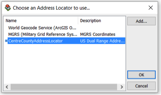
If the address locator you wish to use is not in the list, you can add it. Once you select an address locator and click “ok,” you will be presented with the “Geocode Addresses” dialog (see Figure 3.7).
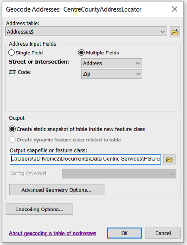
In the top portion of the dialog, you can map the fields in the input table to the corresponding fields in the address locator, if it isn’t done automatically, and define the location and name of the shapefile or feature class where the results of the geocoding process should be stored. You can also configure some parameters for the address locator by clicking the “Geocoding Options” button. The “Geocoding Options” dialog is then displayed (see Figure 3.8).
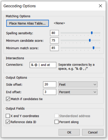
In the top portion of the dialog, you can exercise some control over how matching is performed. The spelling sensitivity level controls the extent to which misspellings will still be considered a match. The lower the score, the more tolerant the geocoding engine is for misspelled words. The minimum candidate score sets the threshold score for identifying candidates. The lower this score, the more candidates an address could have. Finally, the minimum match score establishes the threshold score for declaring a match for the address. Lowering the minimum match score will generally increase the match rate but will also tend to result in a higher rate of false positives.
The dialog can also be used to set other parameters for the geocoding engine such as offset positions for geocoded point features and some output data elements which can optionally be included as attributes in the resultant shapefile or feature class.
Once the geocoding options have been defined, the geocoding process can be initiated by clicking “Ok” on the “Geocode Addresses” dialog (see Figure 3.7). When the geocoding process is complete, a summary of the geocoding results is presented (see Figure 3.9).
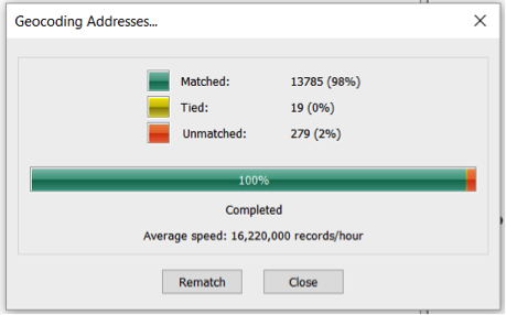
This summary shows the number of addresses which had candidates above the minimum match score (i.e., matches), the number of addresses which had multiple candidates which were above the minimum match score and had the same score (i.e., ties) and the number of addresses which did not produce any candidates above the minimum candidate score (i.e., unmatched).
From the results summary screen, a manual rematch process can be initiated by clicking the “Rematch” button. This brings up the “Interactive Rematch” screen (see Figure 3.10).
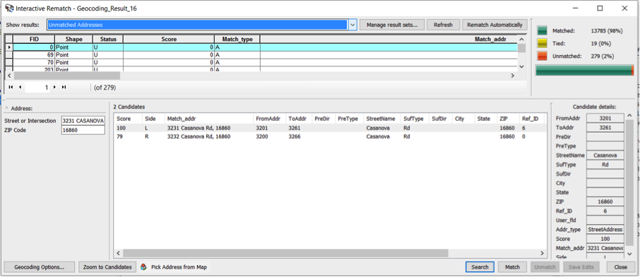
On this screen, unmatched addresses, ties, and matched addresses can be reviewed. Unmatched addresses generally result from either a problem with the address or a problem in the reference data. If a problem is observed with the address, it can be corrected and matched with the correct candidate directly on this screen. Often, however, it is unclear what the problem is with a particular address, and additional research is required to determine where the problem lies before it can be corrected.