Payload refers to air vehicle (aircraft) cargo. It is also defined as the amount of cargo weight an air vehicle can safely carry. Carrying a payload on board is the sole purpose for most UASs. Payloads come in a variety of sizes, weights, and functions. In our business of geospatial remote sensing, we focus on remote sensing sensors and the necessary navigation systems accompanying them. A UAS dedicated to remote sensing and mapping missions is usually equipped with one or more of the following sensors.
Remote Sensing Sensors for the Unmanned Aerial System
- Electro Optical Sensors: such as cameras (still and video, film and digital). Aerial imaging is considered one of the most acceptable applications for UASs. Recent cameras are all digital cameras (versus film). Digital aerial cameras are categorized as follows:
- Large Format Cameras: These are mainly used on board manned aircraft and large UASs. They are very heavy for small and medium-sized UASs. Large format cameras are used to cover large areas, such as entire counties or states. Figure 2.3 illustrates a few of the most common aerial cameras used today.
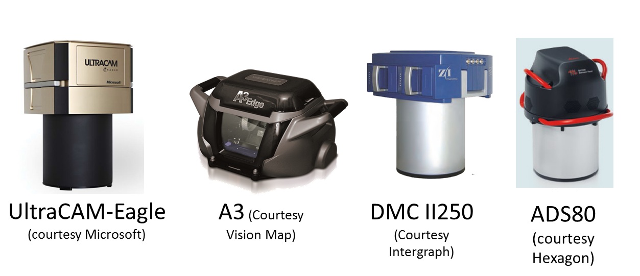 Figure 2.3 Large Format Aerial CamerasSource: (as cited by each image)
 - Medium Format Cameras (not compact): These are cameras that are smaller than large format cameras and more suitable for medium and large UASs. Cameras in this class are still too heavy for small UASs. They are widely used for manned aircraft and can be suitable for large size UASs.
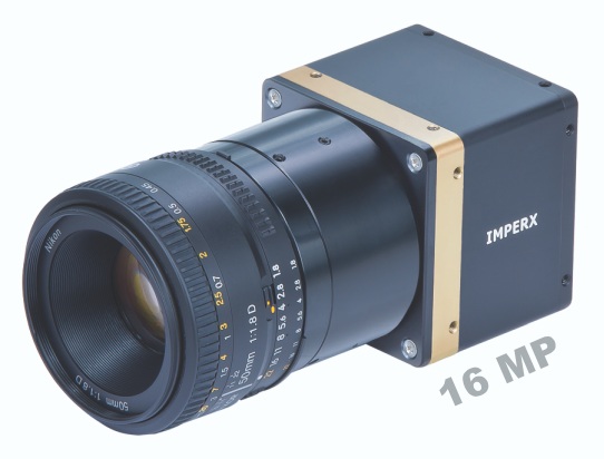
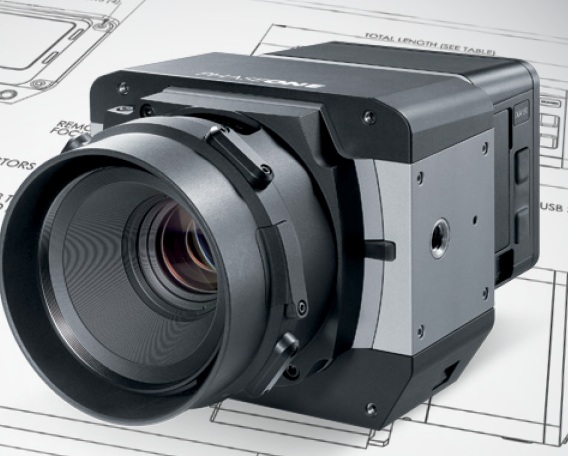
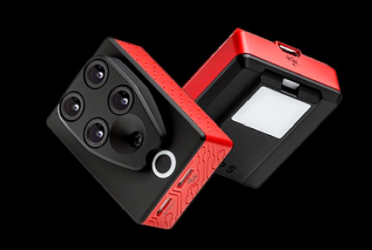
- Small and Medium Miniaturized Format Cameras: This class of cameras is similar to the cameras we own at home and use for recreational purposes, but with compacted size to be suitable for UAS use. Miniaturized cameras are the newest development in the field of digital cameras; they are developed mainly for small UASs. Examples of miniaturized cameras are the Imperx Bobcat 2 camera (Figure 2.4), which has a 16 mega pixel array, weighs only 369 grams (13 ounces) and has a length of 53 mm (2 inches), and the iXA camera system from Phase One Industrial (Figure 2.5). In their latest development, Phase One released their latest payload for UAS, the P3 DJI which is based on mounting an iXA on DJI M300 using DJI mounting hardware and app. Here is additional information about the Phase One suite of sensors for UAS.
- Large Format Cameras: These are mainly used on board manned aircraft and large UASs. They are very heavy for small and medium-sized UASs. Large format cameras are used to cover large areas, such as entire counties or states. Figure 2.3 illustrates a few of the most common aerial cameras used today.
- Infrared Sensors: An infrared sensor operates in the infrared range of the electromagnetic spectrum. Infrared sensors for remote sensing are designed to operate in two regions of the electromagnetic spectrum (EMS), those are:
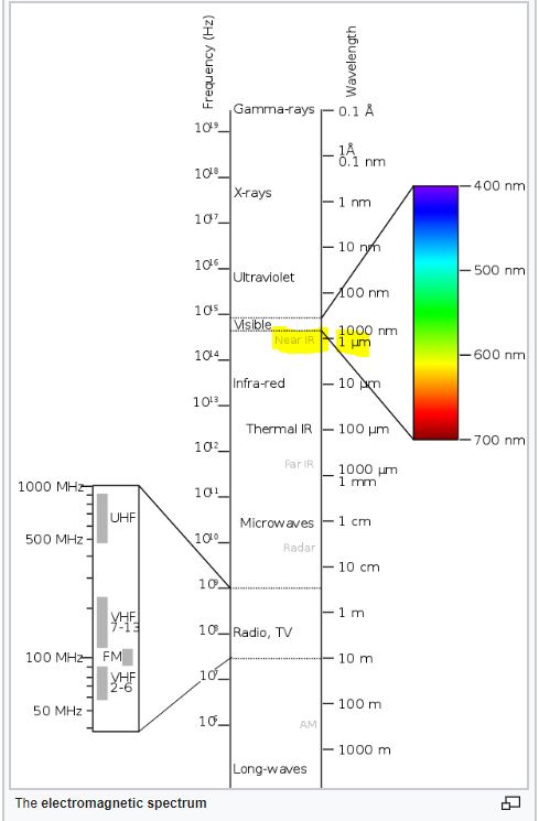
- The Near Infrared Region (NIR): NIR is barely outside the Red of the visible region of the EMS, see Figure 2.6. When the NIR band mixed with the red and green bands of the visible light, it forms a false colored infrared (CIR) image when it is displayed in the order of NIR, R, G instead of the usual R,G,B. False colored infrared imagery is effective in studying vegetation indices and vegetation health and conditions. Precision Hawks runs successful applications for the precision Ag industry. Few sensors designed for UAS to provide multi-spectral imagery, including the NIR band. PARROT SEQUOIA+ is one of those affordable sensors, Figure 2.7.
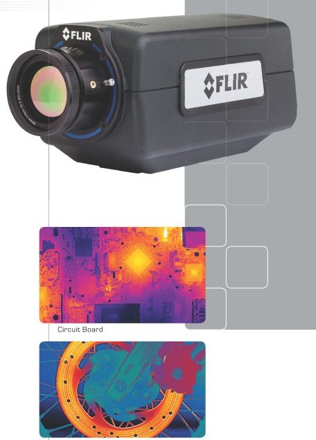
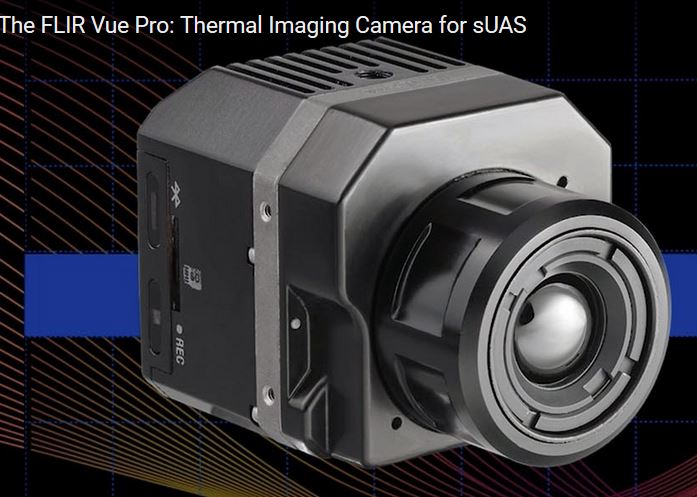
- Thermal Infrared Region (TIR): TIR sensor records the sensed heat and displays it as an image. There are two different technologies used in building such sensors. The uncooled sensor is usually less expensive and less sensitive when compared to heavyweight cooled sensors. Thermal Infrared sensors are widely used for survey and inventory of buried hot water and steam pipes and to inspect heat loss from these pipes. They are also employed for roof inspection, looking for water leaks and heat loss. An example of an infrared sensor is the FLIR A6700SC, shown in Figure 2.8. Recently, FLIR offered a suite of smaller thermal infrared cameras suitable for small UAS such as the VUE PRO, Figure 2.9. In a teaming agreement with DJI, new payloads by DJI such as Zenmuse XT simultaneously carry an RGB camera and a FLIR thermal sensor.
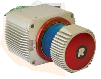
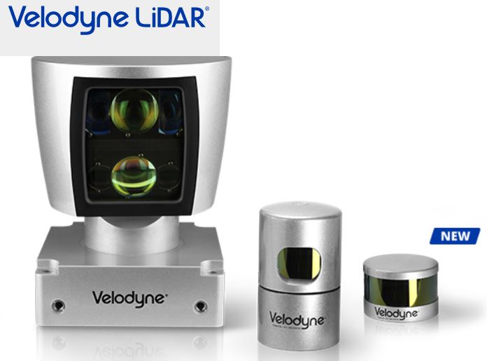
- Laser Sensors: These sensors use laser light for range finding. In addition to the laser source, LiDAR systems use GPS and Inertial Measurement Units (IMU) for precise geolocation of point cloud or terrain mapping. Laser ranging, when combined with necessary auxiliary sensors such as GPS and IMU (see details below), makes a laser-based terrain mapping system called Light Detection and Ranging (LiDAR). LiDAR systems can map the terrain generating point cloud, which can be used to precisely model the terrain below the path of the UAS. Recently, miniaturized laser-based systems started their way into UAS payloads. An example of the compact size LiDAR that is suitable for UAS is the Riegl VUX-1 (Figure 2.10) and Velodyne (Figure 2.11). T o learn more about a few different UAS-based lidar systems and how people are evaluating the quality of its products, I encourage you to watch this video about UAS-based lidar systems evaluation.
- SAR Sensors: Synthetic Aperture Radars are usually employed by the military for reconnaissance purposes. They require large size UASs, as they are heavy. We should not expect a civilian UAS with a SAR system as part of the payload in the foreseeable future.
Auxiliary Sensors for the Unmanned Aerial System
Auxiliary sensors here mean the navigation sensors that are necessary to determine the location and the orientation of the UAS and its remote sensors that are mentioned earlier in this section. For the UAS and onboard sensor position determination, the Global Positioning System (GPS) is used, and for the attitudes or orientation of the UAS and the onboard sensors, the Inertial Measurement Unit (IMU) is used.
Global Positioning System (GPS)
The GPS does not need introduction, as everyone is familiar with its definition. It is the same GPS that you might use to drive around town. However, GPS that is used to determine a remote sensor position usually undergoes a post-processing to enhance the accuracy of the position.
UAS are offered with two grades of GPS accuracies. The most common one is the single frequency GPS receivers as it is cheaper, and it does not require post-processing or real-time correction service. Such receivers provide location accuracy of around 1 to 2-meter. For more accurate geospatial products generation, the more accurate dual frequency receiver and precise services are need needed. The latter receivers offer two modes of operations, both of which yield positional accuracy of 1 to 3 cm with little or no ground controls required for the project. UAS vendors are fielding systems with two operational modes, those are:
- The real-time kinematic GNSS (RTK) mode: This mode of operation allows the UAS to receive in real time GPS positions corrections from GPS correction services. This mode of operation has particular requirements:
- RTK requires a GNSS base station equipped with a transmitter with a reliable link to a fairly dynamic moving platform such as UAS.
- The rover (on the UAS) itself requires a dedicated receiver for the corrections.
- The post-processed kinematic (PPK) mode: This mode of operation does not require the real time GPS positions correction, as the acquired GPS data can be post-processed at a later date. RTK operations not only require a stationary base station during the UAS mission, but the location of such base station should be surveyed and located before the UAS flies the project, something may complicate the deployment of the mission in some circumstances. Although PPK requires a base station as well, the base station’s precise location can be determined later after leaving the project area.
In principle, both RTK and PPK promise positional accuracies at the 1-3cm level. The main purpose of RTK and PPK is to minimize or eliminate the need for ground control points, thereby reducing cost. For more details on GPS, please visit GPS Defined.
Inertial Measurement Unit (IMU)
An inertial measurement unit, or IMU, is an electronic device that measures and reports on aerial vehicle velocity, orientation, and gravitational forces using accelerometers and gyroscopes. IMUs are typically used to control and maneuver manned aircraft, unmanned aerial vehicles (UAVs), and satellites. Another important use for the IMU is that it helps IMU-enabled GPS devices to maintain positioning information when GPS-signals are unavailable, such as in tunnels, inside buildings, or when electronic interference is present.
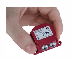
The IMU is the main component of inertial navigation systems (INS) used in aircraft, spacecraft, watercraft, and guided missiles in Geo-spatial mapping activities. The data collected from the IMUs sensors allows us to determine the orientation of the sensor, which is an important aspect in geolocating on the ground each pixel of the sensor. The IMU, like other components necessary for the operation of UASs, is miniaturized in weight and size to make it fit on small UASs. An example of these small IMUs, which are mainly designed for UASs, is the SBG 500E, illustrated in Figure 2.12.
For more details on the IMU, you can visit the IMU Wikipedia page.
To Read
- Section 3.5 of Chapter 3 of Introduction to the Unmanned Aircraft Systems
- Chapter 10, 11, and 12 of Introduction to UAV Systems (Aerospace Series)