Lessons
This is the course outline.
Lesson 1: Introduction and Overview of 3D Modeling and Virtual Reality
Overview
Overview
This course brings into the classroom the ideas and developments that surround both 3D modeling and immersive technologies such as Virtual Reality (VR). The excitement is universal in academia (for over 30 years on and off) and the private sector (more recently) with the expectation of an 80 billion dollar industry by 2025 according to Goldman Sachs (reported on CNBC [1]). It is fair to assume that the geospatial sciences will never be the same once immersive technologies, everything from Augmented Reality (AR), Mixed Reality (MR), Augmented Virtuality (AV), to Virtual Reality, have moved into most people’s living rooms. In the following, we use the term xR or 3D/xR as a combination, to refer to a range of immersive technologies that are available.
Each of the topics that you will encounter in this course could (and is) easily be approached in individual courses! The point of this course is to give students an overview of current developments in 3D modeling and xR that we will keep up-to-date to the best of our abilities, but things are moving and developing fast. Students will encounter some hands-on experience with some of the most versatile and powerful tools for modeling and creating virtual realities such as SketchUp™, Unity3D™, or ArcGIS Pro (not in the residential version). Given the tremendous advancements in 3D modeling and xR that are currently taking place, the course is designed as a timely entry-level course with the goal to give students an understanding of the game-changing nature that recent developments will have for the geospatial sciences. This is an evolving course and any feedback you might have is greatly appreciated.
Learning Outcomes
By the end of this lesson, you should be able to:
- Define 3D modeling
- Define Virtual Reality (VR), Augmented Reality (AR), Mixed Reality (MR), and Augmented Virtuality (AV) (in short: xR)
- Identify, describe, and classify opportunities for geospatial sciences that are not possible in 2D / on regular desktops
- Find examples of 360 videos
- Find examples of 3D models
- Explain the difference between models and videos
- Explain the differences between VR, AR, AV, and MR
- Detail how immersive technologies will change the geographical/spatial sciences
Lesson Roadmap
| To Read |
|
|---|---|
| To Do |
|
Questions?
If you have any questions, please post them to our "General and Technical Questions" discussion (not e-mail). I will check that discussion forum daily to respond. While you are there, feel free to post your own responses if you, too, are able to help out a classmate.
1.1 Distinguishing VR, AR, and MR Systems
1.1 Distinguishing VR, AR, and MR Systems
To give you an idea of current developments in the field of Virtual Reality, Augmented Reality, Augmented Virtuality, and Mixed Reality, we would like you to watch the following videos and think about and reflect on the core differences in the technologies they use.
The first video gives you a quick overview of a collaboration between Microsoft and NASA using Microsoft’s Hololens. Please do feel free to dive deeper into the diverse application scenarios that are envisioned for the Hololens and related products!
Video: Mixed-Reality Tech Brings Mars to Earth (1:40)
At NASA, we're excited to apply mixed-reality technologies to the challenges we're facing in space exploration. Through a collaboration with Microsoft, we're building applications to support engineers responsible for the design and assembly of spacecraft. Astronauts working on the International Space Station and scientists are now using our Mars tool, OnSight, in mission operations. OnSight is a powerful tool for our scientists and engineers to explore Mars, but because we always felt it shouldn't remain only within NASA, we've taken the core of OnSight and made an amazing experience that allows the public to explore the red planet. We call this new experience Destination: Mars.
Mars can be a lonely place, so we've added photo-real holographic captures of an astronaut and a member of the Curiosity rover team to be our guides on this journey. This gave us the opportunity to immortalize a hero.
Hi there, I'm Buzz Aldrin.
To help Buzz explain how we're doing science on Mars today is Curiosity rover driver Erisa Hines. Welcome to my office. We can put the public, the rover and Erisa together at the exact place where Curiosity made some it's most amazing discoveries. We're looking forward to opening the Destination: Mars exhibit at the Kennedy Space Center Visitor Complex in summer 2016. We can't wait to share this journey with the world.
Let's go to Mars!
The second video provides you with an overview of the next generation MR headsets. The new HoloLens 2 by Microsoft provides infinite possibilities for users to interact with high-quality holograms that can be in the form of animated models of objects, conversational agents, natural phenomena, etc. The term that Microsoft is using to characterize the HoloLens products is “mixed reality”. What do you think this actually means?
Video: HoloLens 2 AR Headset: On Stage Live Demonstration (10:59)
Today I get to show you something very special. It's something we've been looking forward to for many years. When we set out to build HoloLens 2, we wanted to create some things that you didn't need to learn how to use. You should just know it. And we call this, instinctual interaction. Let me show you. Now, as I mentioned the HoloLens is very comfortable, it fits just like a hat. And the only thing that's even more effortless is how I'm automatically signed in. With Windows Hello and RS syndication, the Hololens 2 is actually signing me in as I put on my device. Now, not only does the Hololens 2 recognize me, it also recognizes my hands. Look at this. Fully articulated hand tracking. And as I move my hands around, the Hololens is actually calibrating to my unique hand size. And of course, not only does the Hololens 2 recognize me and my hands, it also recognizes the world.
Welcome to my mixed reality home. This is the place where I have all the apps and content that I use every day. Let's check some of them out. Now, I've seen many people put on HoloLens for the first time and the first thing people do when they put on the device is they reach out their hands and try and touch the holograms. And now you can. Look at the way that the hologram is responding to my hand, almost inviting me to touch it. And, in fact, I can just grab this corner to resize it. Or I can rotate it or move it. That's right, we are touching holograms. This is an app I've got called spatial. Let me just put it right there. I've got another app here called vurfoiral view. It's a little big, so let me just use two hands here to make it smaller and then rotate it so you can see. There we go. And then let me put it down here near spatial. Maybe make it bit smaller. Yeah, that's nice.
Alright, now let's switch gears and talk about a different kind of application. I've got a browser over there but it's kind of far away and I don't really want to walk over there. So let me just call it over with my voice, "follow me". This is a browser that's running Microsoft Teams, which is a tool that we use back home to collaborate. Let me see what the team's been working on. Ok, it looks like they've got a surprise for me in the playground app. I just have to say the words, "show surprise". Alright, so let me just open up that Start menu here, and then place the app and then launch it.
So now we're actually exiting my mixed reality home and going into an immersive experience. But notice that that browser that I had, actually followed me in. Now, this can actually be really useful when you have things like emails or PDFs that you need to reference while you're doing your work. I don't really want it following me around though, while I'm showing you all this cool stuff. So let me just put it over here and then we'll get back to it later.
Welcome to the playground. We spent years exploring and refining interactions for HoloLens2 and the playground's just a tiny sampling of the many prototypes that we built, tested and learned from. Our approach was basically to try out as many things as we could and look for the things that stood out. So, for example, here I've got three sliders. Each of them is controlling this wind farm simulation, but each in a different way, using a different interaction technique. One of the things we tried is this touch slider here. So here I can just stick my finger in the slider and have it go to a particular value to control that wind speed there. It felt okay. We also tried this push slider. So this guy you kind of nudge from side to side, kind of like an abacus, which was interesting. Now the interaction that really took home the cake though, was this pinch slider. The way that works is you just pinch it and move it wherever you want. And what we found was that people really like that tactile sensation of their fingers touching as they grab and then release. And across the board, for all interactions, the audio and visual feedback as a grab, move, and then release, were all really critical for making this experience feel connected. Oh, this is just so satisfying. I can't wait for you all to try this out.
Alight, now let's move on to a different kind of control, buttons. How do you press buttons on HoloLens 2? Well, you just reach out and press them. Now, one interesting thing that we found about buttons was that the size of the buttons actually impacted the way that people interacted with them. So, for example, for the smaller ones, most people would use one or maybe two fingers. But for the larger ones, pretty much everyone used their entire hand. And this is kind of interesting when you think about it because these objects don't really weigh anything. They're just digital things. But despite that, people would treat them like real things, almost as if the bigger one had more weight. I just love the way these move and the sounds they play when I press them, it's great. Alright, how about something that uses all ten fingers. Well, to test that out, we built a piano. So here I can just play a chord or I can play the keys one at a time. [Music]
Alright, so where's that surprise that the team had for me? Oh, that's right, I had to say those words. Show surprise. Ooooh, look at that hummingbird over there, it's gorgeous. I wonder if it will fly to my hand. Yeah. Oh wow. This is beautiful. I just love the way that it's following my hand around. I've got to tell the team they've done a great job. And in fact, I don't even need to use my hands to do this because I can use my eyes and my voice. That's right HoloLens 2 has eye-tracking. So I could just look over to this browser here and look at the bottom of the screen to scroll it, and then send my message. Start dictation. The hummingbird looks great, exclamation mark. Send.
So this is what we mean by instinctual interaction. By combining our hands, our eyes, and our voice, HoloLens two works in a more human way.
Anand Agarawala: Today companies tackling the world's biggest problems are increasingly spread across the world. And the hololens lets us work together as if we were standing next to each other face-to-face. To show you how that works, let me just flip into spatial here with my HoloLens 2 and materialize the room. Hi Jinha!
Jinha Lee: Hi everyone, it's great to be here on stage holographically.
Anand: It's great to have you here Jinha. Can you tell everybody a little bit about what you're seeing?
Jinha: Sure. I can see your lifelike avatar which we generate in seconds from a 2D photo. And we can walk around the stage with spatial audio and use this whole space around us to collaborate as if we're all here together in the same room.
Anand: Cool. Now to show you how companies are using Spatial to transform the way they work, let's invite Sven Gerjets, CTO of the iconic toy brand Mattel onto the stage.
Sven: Hey guys, how awesome is this. So at Mattel, we're undergoing a massive digital transformation. It's touching all aspects of our business. This includes the way that we're using technology to design and to develop our products. Our classic brands like Barbie and Hot Wheels and Fisher-Price, they have diverse teams of designers, engineers, marketers, and manufacturers that are spread all over the world. They can now come together in a spacial project room, reducing the need to travel as much, to get everybody on the same page. When we're developing toys, like this Rescue Heroes Fire Truck here, we're able to pin up dynamic content on virtual walls, like this powerpoint for instance, or videos, or even concept art. Teams can now rapidly exchange ideas and create a shared understand you to find potential issues much earlier in the cycle. For instance, guys, take a look at this wheel clearance here.
Anand: Oh yeah, I can see that's gonna be a problem. So I can pull out my spatial phone app and write a quick note, and then just hit Send, and it becomes a digital sticky note, which I can just grab and stick right on to the fire truck so that we can have engineering revise this later.
Sven: We can also use spatial much earlier in our design process to ideate and generate inspiration. Okay, guys, let's come up with some ideas for a line of aquatic toys.
Anand: Yeah, how about sea turtles.
Sven: Oh, that's really cool. Let's try sharks.
Jinha: That's cool how about jellyfish?
Anand: So all we have to do is say the words and they're instantly visualized right before our eyes. You can even click into one of these bundles and they expand it to a full-blown internet search, complete with 3d models, images, and webpages. Jinha, why don't we click into just the images here so we can get some good inspiration for this new aquatic line.
Jinha: Mm-hmm, sure. Every object you see in spatial is physical and tactile. So you can scroll through or pick up images you like and toss them up on the wall with physics.
Anand: And we don't have to just stick with digital content, I can actually pull up these sketches I did on my phone last night using that same spatial app. I just pull up those photos and hit Send and they're instantly transformed into this digital environment.
Jinha: Nice drawings. It's so easy to fill up your room with ideas, so we built this tool to help you quickly organize all these ideas. So let me select all of these and let's make a grid. This goes to the wall.
Anand: Now this entire room we've created is a persistent digital object that anyone can access or contribute to at any time, whether they're using an AR or VR headset or even a PC or mobile phone.
Sven: So that's right, now we can have virtually rich visual rooms that we can keep up for the life of the product. That means no more tearing down war rooms all the time. So Spatial and HoloLens are helping us drive improvements in our digital design and development process changing the way we create new toys. By bringing people together from all over the world to collaborate in the same virtual room, we're overcoming a natural barrier to our collective success, that's people's desire for direct face-to-face interaction when building commitment and trust. We're so excited to see faster time-to-market and reduced need to travel, as well as the many other benefits that we're gonna unleash at Mattel, as we collaborate in mixed reality.
The third video is a nice way of showing experiences in VR by placing users in front of a green screen. This adds a bit more information than filming people who are experiencing VR and then communicating the experience through their reactions. You probably have seen plenty of those videos showing people of hesitating to walk over a virtual abyss they know physically does not exist, playing horror games, or experiencing a different body. The HTC Vive that is demoed in the video below, like the Oculus Rift, is a high-end head-mounted VR system that requires a relatively powerful computer.
Video: Virtual Reality - SteamVR featuring the HTC Vive (4:29)
Sound of a box opening
Background Conversations
Valve Headquarters, WA
That's very green.
Come on in. So we're going to show you some virtual reality today. You know it's really hard to show people what it's like to be in virtual reality without having them try it for themselves. Filming you in the green screen studio is just the best way we found to help everyone else understand what it's like to be in VR. Any questions?
Can I go first?
Laughing.
All right, go crazy!
Hi! Awe, you're so cute! Oh. Laughing. Oh, he's doing a little trick. Oh. Hey, I have a stick now. Come here. You want the stick? Go get it! Laughing. He actually gets it. Come on. Oh, you're so cute.
It makes you feel like you're pulling a string back.
Left, check left.
Ooooh. Oh yeah. Nice shot.
No way! Laughing.
Hh my goodness, these guys are so cool.
Look behind you Kyra.
Screaming. Laughing.
Order up.
Ohhh. Bacon.
Oh no.
Computer voice: Is that how you cook for your family. How human.
It's burned.
Eat those doughnuts, get 'em. Get those donuts.
I don't want to stand in the way of his ball.
A little bit more toward us. There you go.
Laughing. Yay!
No, the other way, the other way. The wheels are a little off-kilter.
Hold on, hold on, I'm gonna get really hunkered down here. A little bit of a torque issue.
Yeah. There you go.
Right into the black hole. Yay! Laughing. Clapping.
What?
Kelly, go into space?
No, I can't, the grids here.
The grid wall here has to stop you from walking into the couch, walking into the walls.
Oh, this is so cool. I can move all this stuff.
Oh, oh, oh.
Look at this thing.
Laughing.
You've gotta keep with the beat.
Wha. Wha.
Ohhh. That was good.
Can you see me?
Yes. Hold up some fingers, let me see if...five!
Oh no! Laughing.
Oh my God.
Use both of your guns Kelly.
Oh, we have a little fire. It even feels hot, I think. I'm pretty sure I feel it.
The fourth video is a potpourri of systems that are referred to as augmented reality. It is rumored that Apple will be focusing on augmented reality technologies and you may have played Pokemon Go. It is important to note that there is a difference between Mixed and Augmented reality. In the former, virtual elements are embedded in the real environment in such a way that they provide the illusion that they are part of the environment. This illusion is enforced through virtual elements abiding with the laws of physics that govern our reality (e.g. a virtual robot that can collide with a physical table). Augmented reality, on the other hand, does not necessarily follow this principle.
Video: Augmented Reality Demo (2:15) This video is not narrated, music only.
The last video demonstrated the concept of Augmented Virtuality. The concept of AV refers to the idea of augmenting the virtual experience with elements of reality. An example of this approach could be the user of 360 degrees images and videos in a VR experience.
Group Discussion: VR Concepts
We invite you now to reflect on the different technologies that have become available in the last couple of years and that you have seen in the three videos above.
- What are the defining characteristics of Virtual Reality, Mixed Reality, Augmented Virtuality, and Augmented Reality?
- Are they different and if so what is the main distinction, which one is most useful for the geospatial sciences?
- Which system will become a mass-produced product?
- What are the advantages and disadvantages?
Your Task
Please use the Lesson 1 Discussion (VR Concepts) to start a discussion about this topic using the questions above as a guide. Active participation is part of your grade for Lesson 1. In addition to making your own post, please make sure to comment on your peers' contributions as well.
Due Date
Your post is due Saturday to give your peers time to comment. All comments are due by Tuesday at 11:59 p.m.
1.2 VR Systems
Introduction
1.2 VR Systems
Introduction
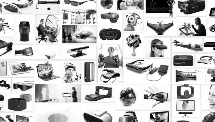
It is impossible to write a complete list of all the [A,M,V]R systems and content providers that are currently throwing their products on the market. Essentially, all major tech company and numerous startup companies are venturing into the field of VR. We are providing a short overview of some of the main systems that are available or are filling niche products. The image below provides a visual overview and a little farther down the line we have a quick memory game for you.
Oculus Rift
Oculus Rift
It is fair to say that the current hype around VR has been dramatically spurred by Oculus and the fact that a little startup company after only two years got purchased by Facebook for two billion dollars (see Mark Zuckerberg's announcement [3]) [4].
Oculus started with a then teenager, Palmer Luckey, who was building VR prototypes in his garage (are not all stories like this starting in garages)? Luckey sent one of his prototypes, the PR6 that he called the Rift, to famous game designer John Carmack (Doom, Quake, founder of id Software). Carmack a little later would demo the Rift at an E3 event where it created a lot of traction. Luckey teamed up with Brendan Iribe, Michael Antonov, and Nate Mitchell, and together they launched a Kickstarter Campaign, that raised not the anticipated $250K but over 2 million dollars (for more details see "How Palmer Luckey Created Oculus Rift [5]".
From there on it was a wild ride. The biggest change for the young company came when Facebook in 2014 bought it for two billion dollars. Had VR, even up until March 2014 created some hype and fantasies, at this point it had everyone’s attention.
After two developer versions, the consumer version started shipping in the Spring of 2016! Below is a figure that shows the transition from DK1 to the consumer version. The latter offers an OLED display, a resolution of 2160 x 1200, a 90 Hz refresh rate, a 110-degree field of view, and a tracking field of up to 5 x 11 feet. The Oculus Touch controllers have not yet been released. If you want to run an Oculus on your computer the recommended minimum specs are an NVIDIA GTX 970 / AMD 290 equivalent or greater, Intel i5-4590 equivalent or greater, 8GB+ RAM, Compatible HDMI 1.3 video output, 2x USB 3.0 ports, Windows 7 SP1 or newer.
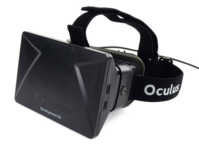
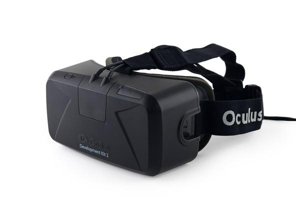
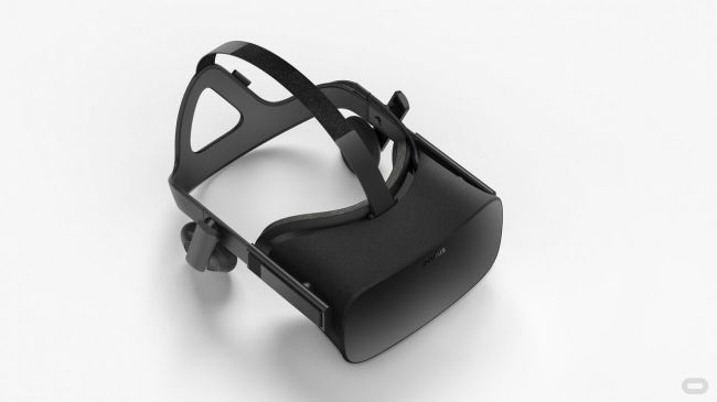
The latest versions of Oculus Rift can be used with either a remote controller or a more complicated
input modality such as Oculus Touch.

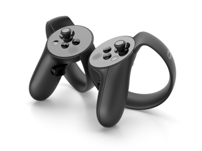
While the remote is rather limited as an interaction modality (only a few buttons), Oculus Touch provides a wide variety of interaction possibilities (e.g., finger tracking, gesture recognition) and a larger set of buttons on each controller.
Moreover, by default two Oculus sensors are used to track and translate the movements of users (head movements based on the VR headset and hand movements based on the Touch controllers) in VR. This technology provides a 6-DOF (degrees of freedom) (3-axis rotational tracking + 3-axis positional tracking) tracking.

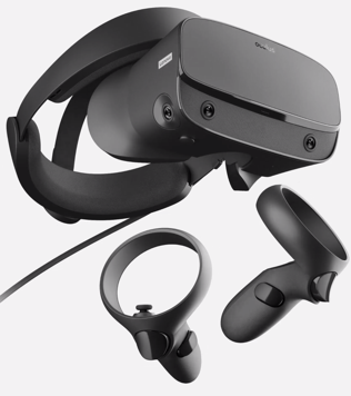
On March 20th, 2019 Oculus announced a new model to the Rift family called Oculus Rift S. The new member of the Rift family uses a Fast-switch LCD display with a resolution of 2560×1440 (1280×1440 per eye) with a refresh rate of 80 Hz. It utilizes a new technology called “inside-out tracking” using five cameras embedded into the headset, which eliminates the need for external sensors for tracking while maintaining a 6-DOF tracking. In short, the headset itself can track and translate the movements of itself and the controllers, which allows the users to freely move around a physical environment without restrictions. If you want to use an Oculus Rift S on your computer the recommended specs are an NVIDIA GTX 1060 / AMD Radeon RX 480 or greater graphics card, Intel i5-4590 / AMD Ryzen 5 1500X or greater, 8GB+ RAM, DisplayPortTM 1.2 / Mini DisplayPort, 1x USB 3.0 ports, and Windows 10.
Since the emergence of cost-effective VR HMDs developers and users have always been restricted to limited mobility options due to the requirements for these HMDs to be connected to powerful computers via cables (i.e. tethered).
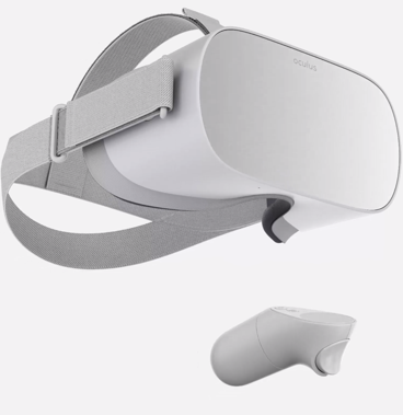
On October 11th, 2017 a new generation of Oculus HDMs called “Oculus Go” was announced and later on May 1st, 2018 released to the public. Go is described as an untethered all-in-one headset meaning that it can function as an independent device without the need to be connected to a computer. Evidently, the first generation of these untethered all-in-one headsets was not as powerful as their predecessors in terms of computing power. Oculus Go utilizes a Snapdragon 821 SoC processor and is powered by a 2600 mAh battery, 5.5" fast-switching LCD with a resolution of 2560×1440 (1280×1440 per eye) and refresh rate of 72 Hz, Adreno 530 internal graphics card, with non-positional 3-DOF tracking due to the lack of sensor use. Unlike the Rift, Go does not use rich controllers such as “Touch” but instead, uses a simple remote controller with limits interaction possibilities. On December 4th of 2020, Oculus discontinued the Go HMD and officially replaced it with the next generation, Quest.
On May 21th, 2019, Oculus released a new breed of untethered all-in-one headsets called Oculus Quest. This HMD brings the best features of Rift and Go together in one. Similar to Go, it is an all-in-one standalone headset, and similar to the Rift it uses inside-out-tracking with 6-DOF. Furthermore, it utilizes a more powerful GPU and processor (4 Kryo 280 Gold processor with 4GB RAM, and an Adreno 540 graphics card), capable of running high-quality applications. It has a PenTile OLED display with a resolution of 1440 × 1600 per eye, and a refresh rate of 72 Hz. Furthermore, unlike the other untethered Oculus product Go, Quest uses the latest version of touch controllers.
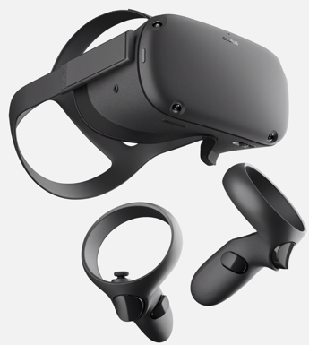
On October 13th, 2020, Oculus released the new generation of Quest, called Quest 2. This new generation of the Quest HMD has superior specifications in the processor (Qualcomm Snapdragon XR2), RAM (6 GB), and display resolution (1832 x 1920 per eye) and starts at a very competitive price of $299.

HTC Vive
HTC Vive
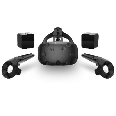
The HTC Vive is a collaboration project of software company Valve and tech giant HTC. Not going into any details of how they came together, the Vive is a truly awesome product that offers substantial flexibility and sophisticated interaction opportunities. The main difference to the Rift is that it does not require users to remain in front of a computer screen (or a fixed location). The Vive comes with room sensors that allow users in small spaces to actively move around (you saw the intro VR video [7]), which is awesome. Additionally, the controllers allow for tracking locations of hands, provide advanced interactivity, and provide haptic feedback in the form of vibrations.
It is always very difficult to explain experiences one has in a VR environment like the Vive to someone via text … one of the best solutions without actually experiencing it oneself is this video filmed using a green background (see intro video [8] again).
The Vive also has a 2160 x 1200 resolution, offers a 90 Hz refresh rate, and a 110-degree field of view. In contrast to the Rift, the tracking field is 15 x 15 feet. The minimum computing requirements are similar to the Rift: NVIDIA GeForce GTX 970 /Radeon R9 280 equivalent or greater, Intel Core i5-4590 equivalent or greater, 4GB+ of RAM, Compatible HDMI 1.3 video output, 1x USB 2.0 port.
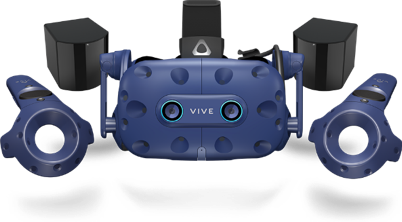
On January 8th, 2018, HTC released an updated version of Vive called Vive Pro. The new HMD has a higher resolution at 1440 x 1600 resolution per eye and a refresh rate of 90 Hz. Thanks to its sophisticated tracking sensors (called lighthouses) Vive provides up to 22’11” X 22’11” room-scale tracking of headset and controllers. Vive Pro is also equipped with two cameras embedded into the headset, facing outward. These cameras can be used to bring the real world into VR (Sounds similar to a type of xR previously discussed?). Moreover, Vive affords multi-user interaction in the same physical space. Notwithstanding, each user requires their own dedicated computer and play-area.
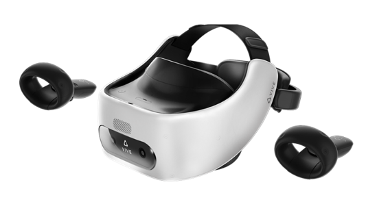
In November 2018, VIVE released their first untethered all-in-one headsets called Vive Focus. The focus utilizes inside-out-tracking technology and affords 6-DOF tracking. It has a 3K AMOLED display, with a resolution of 2880 x 1600 and a refresh rate of 75 Hz, and a Qualcomm Snapdragon™ 835 processor and two controllers.
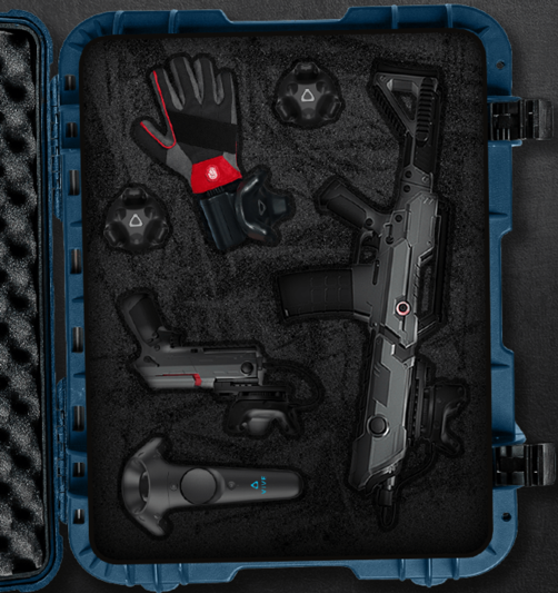
In addition to awesome and popular HMDs, VIVE also provides a variety of external sensors and controllers that can be used to create a much richer and close-to-reality VR experiences. These include trackers that can be attached to arms and legs to provide a feeling of embodiment of users in VR (tracking and projecting the hand and leg movements of users in VR), controllers that look like weapons, and VR gloves that cater for hand and finger actions in VR while providing haptic feedback to users.
Other HMDs
Other HMDs
There are numerous other HMD brands such as Samsung GearVR, Nintendo Lab VR kit, Sony PlayStation VR, Lenovo Mirage, etc. with different specifications. Going into details about each and every one of these different brands would be out of the scope of this lecture. Notwithstanding, it would be of great interest to become familiar with some of the HMDs are go beyond the conventional specifications.
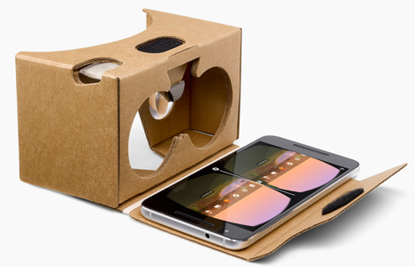
Although not new, Samsung’s GearVR is of the most affordable (but limited) HMDs. Instead of requiring the user to purchase his or her own computer, it works with various Samsung Galaxy phones. You can think of it as a fancier version of the Google Cardboard viewer. While the Cardboard viewer essentially works with every smartphone, the GearVR requires a Samsung phone although in its newest release the GearVR accepts a range of Samsung phones. While the Cardboard viewer is somewhat limited in its interactive capabilities (gaze and the little magnet button on the side), the GearVR has a back button and a little trackpad on the side. Computing power and display characteristics will depend on your phone.

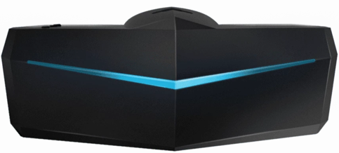
While most VR HDMs have a field of view (FOV) of around 110 degrees, Pimax is an HMD with a FOV of 170-200 degrees (close to human vision). It has an 8K resolution (3840 x 2160 per eye) with a refresh rate of 80 Hz and is tethered. In addition to being compatible with a variety of controllers (e.g. HTC Vive controllers), Pimax has a special Leap Motion [12] module embedded in the HMD. This module provides real-time and accurate hand tracking and can enable users to solely use their hands as the interaction modality. Furthermore, as another addition to its modular system, Pimax utilizes an eye-tracking module that can provide real-time tracking of users’ eye movements while interacting with a VR experience. Such information will be useful for an array of research topics, including usability studies, user-behavior analysis, and learning content adaptation. The high FOV provided by Pimax enable users to perceive the virtual environment in a way much closer to real life. This can potentially set the basis for more effective training of visual-spatial skills in VR and a more successful transfer of these skills to real-world contexts.
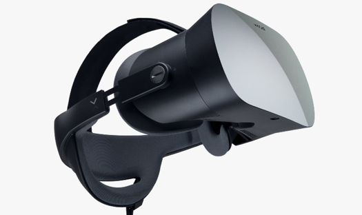
As is evident from the different HMDs we have seen so far, the resolution of these devices has improved significantly over the past few years. Notwithstanding, they are still not comparable to high-end desktop experiences in that respect. As one of the main applications of VR HMDs is training via realistic simulations, display quality and high-resolution imagery can play a determining role in the successful realization of learning goals in these applications. For this exact reason, the Varjo company has released a VR HMD called Varjo VR-1. Standing at almost 6000$, it is one of the most expensive HMDs in the market, but it possesses unique characteristics. It has a Bionic display – human eye-like resolution of 60 Pxl per degree and combines a 1920x1080 low-persistence micro-OLED and a 1440x1600 low-persistence AMOLED. It is important to note that this HDM is not targeted at average consumers, but rather for AEC (architecture, engineering, and construction), industrial design, virtual production, healthcare, and training and simulation. Given the fact that resolution is one of the drawbacks of VR which impedes its proper utilization in simulations and application where detailed graphical elements are important (e.g. creation of artwork in VR, reading long texts in VR, surgery simulation, interacting with a cockpit panel with lots of buttons and small labels, etc.), this HDM opens the door for interesting research opportunities. Furthermore, it has a built-in eye-tracking module that provides researchers with a great opportunity to monitor the behavior of users when interacting with a VR experience for the purposes of usability studies, measurements of attention/interest, user behavior studies, and content adaptation.
The bottom line is that there is a tremendous amount of development on the VR market that is spurring developments in industry and academia. We just gave you a little glimpse of some of the most prominent examples but there are many, many more. To further acquaint you with some of the technologies we have two tasks outlined on the next page.
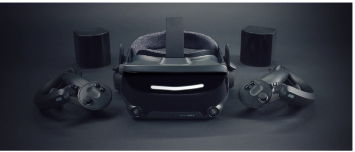
On June 28th, 2019, Valve released the first of their second-generation HMDs called Index. Valve Index has a display resolution of 1440 x 1600 per eye and a refresh rate of 120 Hz. Valve index is backward compatible with all HTC products including the Vive HMDs and the lighthouses (base stations used for tracking). It comes with a new generation of the lighthouse sensors (base station 2.0) that offer improved tracking range, better field of view, and potentially a 300 percent larger tracking space. Perhaps one of the most delightful features of the Valve Index is the novel controllers (called Knuckles) that are significantly more ergonomic compared to other controllers on the market.
Test Your Knowledge
This is an ungraded assignment to test your knowledge.
Assignment
Graded Assignment (Product Review)
Find a product related to [A,M,V]R, not covered in this section that you are excited about. Write a one to two paragraph description, add a picture and submit your response to the Lesson 1 assignment.
Due Date
Please upload your assignment by 11:59 p.m. on Tuesday.
Guidelines and Grading Rubric
- The product needs to be different from the ones discussed above.
- The write up should contain some technical specifications.
- The image, ideally, does not have copyright issues (e.g., use press release kits, wiki commons, Flickr, etc.) and you provide proper source information.
- Writing should clearly communicate your excitement about the product, should be grammatically correct and without typos.
| Criteria | Full Credit | Half Credit | No Credit | Possible Points |
|---|---|---|---|---|
| Product described is different from course examples. | 2 pts | 1 pts | 0 pts | 2 pts |
| Image provided is not copyrighted. | 1 pts | .5 pts | 0 pts | 1 pts |
| Write up is well thought out, researched, organized, contains some technical specifications, and clearly communicates excitement. | 3 pts | 1.5 pts | 0 pts | 3 pts |
| The document is grammatically correct, typo-free and cited where necessary. | 1 pts | .5 pts | 0 pts | 1 pts |
|
Total Points: 7 |
1.3 3D Modeling and VR in the Geospatial Sciences
1.3 3D Modeling and VR in the Geospatial Sciences
"At the time of writing, virtual reality in the civilian domain is a rudimentary technology, as anyone who has work a pair of eyephones will attest that the technology is advancing rapidly is perhaps less interesting than the fact that nearly all commentators discuss it as if it was a fully realized technology. There is a desire for virtual reality in our culture that on can quite fairly characterize as a yearning." (Penny, 1993: 18; in Gillings, 2002)
The Geospatial Sciences have an intricate relation to 3D modeling and VR. While representations of our
environments have been largely in 2D, that is, maps in the past centuries, there also have been efforts to make 3D information part of the geospatial toolset. This does not come as a surprise if we look outside the USA where GIScience is often part of Geomatics (surveying) departments, for example, in Canada and Australia. Interest in VR and 3D modeling has always come in waves so far, that is, people got interested and excited about the prospects of having 3D models and virtual access to these models (see quote by Penny above), started implementing systems and theorizing about the potential, and then gave up as they ran into too many obstacles. Looking into one such effort, a workshop and subsequent book project led by Peter Fisher and David Unwin (2002) summarized the state of the art in geography more than a decade ago and identified prospects and challenges of using VR:
- Ergonomic issues such as feeling disorientated and nauseous also referred to as motion or cybersickness.
- Substantial costs for everyone who wants to use a VR system.
- A rather complex technology for getting content to users in comparison with other media such as the World Wide Web.
If we look at these problems from today’s perspective, we can confidently assert that most of these problems have been resolved (if not all of them). Motion sickness is largely taken care of by advancements in computing technology, that is, better sensor technology and higher framerates allow for almost perfect synchronization of proprioceptive and visual senses reducing or eliminating motion sickness. And, if anything, this is a development that will get even better in the near future as graphics card manufacturers such as NVIDIA or AMD are now developing new products for a growing market, not just a niche. Check out the specs of the new NVIDIA GTX 1080 in comparison to older models GEFORCE [16]. Some problems still persist. It is still not the case that everyone feels comfortable in a VR environment and some people still get motion sick; unfortunately, it is worse if you are old or not getting enough VR time. However, we are getting very close to weed out ergonomics issues that have been standing in the way of mass deployment of VR.
As you see with the Cardboard version of a VR experience, the one that we have sent you, it is possible to get content into people’s hands rather easily. All you need is a smartphone and some apps. This still does not include high-end applications such as Oculus Rift or HTC Vive as they require hardware as well as a beefy gaming computer, but with the advancements in computing power and the availability of low-cost VR ready system, it is only a matter of time until essentially everyone will be able to access a VR (or AR or MR) system.
Likewise, the issue of VR being a rather complex technology does certainly not stand in the way any longer. While VR and 3D modeling are still requiring some training for people who would like to dive deep into software and content development, creating a simple VR experience is as easy as pressing a button. The intro video that you can find on the introductory page is created using a Ricoh™ Theta S, a 360-degree camera that can be purchased via Amazon™ for about $350. During the development of the course, the software app that comes with this camera has drastically improved and allows now for watching videos in the viewer and has a direct upload to YouTube (rather than having to infuse 360-degree videos with additional information, which was the case in May 2016).
So what is remaining as a challenge for VR to become omnipresent in the geospatial sciences and to enter the mass market? Interestingly, in a recent survey, the lack of content has been identified as one of the main remaining obstacles (Perkins Coie LLP & UploadVR Inc., 2016). This is, in my humble
opinion, one of the biggest opportunities for the geospatial sciences. With a long-standing interest in organization information about the world in databases, scanning and sensing the environment, and, more recently modeling efficiently in 3D with geospatial specific approaches and technologies, geospatial is potentially playing a critical role in the developing VR market, and benefitting from it in return. We shall see whether this prediction holds.
For a long time, people have been building 3D models not in the computer but by using physical miniature versions of buildings. The Figure below shows a nice example of the 1630 city of Göttingen, Germany. To get an idea of the current status quo of 3D modeling from a GIS perspective we would like you to read a white paper published by Esri in 2014. Please be advised that there will be questions in quizzes and the final exam on the content of the white paper.
Download paper linked below
3D Urban Mapping: From Pretty Pictures to 3D GIS (An Esri White Paper, December 2014) [2]

References
Fisher, P. F., & Unwin, D. (Eds.). (2002). Virtual reality in geography. London, New York: Taylor & Francis.
Gillings, M. (2002). Virtual archaeologies and the hyper-real. In P. F. Fisher & D. Unwin (Eds.), Virtual reality in geography (pp. 17–34). London, New York: Taylor & Francis.
Penny, S. (1993). Virtual bodybuilding. Media Information Australia, 69, 17–22.
Perkins Coie LLP & UploadVR Inc. (2016). 2016 Augmented and Virtual Reality Survey Report. Retrieved from https://dpntax5jbd3l.cloudfront.net/images/content/1/5/v2/158662/2016-VR... [18]
1.4 Applications of 3D Modeling
1.4 Applications of 3D Modeling
3D modeling was expensive in the past. With the availability of efficient 3D workflows and technologies that either sense the environment directly (such as LiDAR and photogrammetry) or use environmental information to create 3D models (such as Esri CityEngine's procedural modeling, see Lesson 2 and 4) it is now possible to properly use 3D models across academic disciplines. While there is still an ongoing debate to which extend 3D is superior to 2D from a spatial thinking perspective and there is, indeed, beauty in abstracting information to reveal what is essential (see London subway map [19]), there is also, without a doubt, a plethora of tasks that greatly benefit from using 3D information. For example, whether or not you are gifted with high spatial abilities, inferring 3D information from 2D representations is challenging. Below is a quick collection of topics and fields that benefit from 3D modeling and analysis (see also Biljeki et al. 2015):
- Estimation of shaded areas to calculate reduced growth areas for agricultural planning.
- Estimation of solar irradiation.
- Energy demand estimation.
- Urban planning.
- Visualization for navigation.
- Forest management.
- Archeology.
- Visibility analysis.
- Identifying sniper hazards.
- Orientation and wayfinding.
- Surveillance camera positioning.
- Noise propagation in urban environments.
- Flooding.
- Cultural Heritage.
- Communicating Climate Change.
References
Group Discussion (Application of 3D Modeling)
Can you think of additional areas of application of 3D modeling not mentioned above?
The Task
Use the Lesson 1 Discussion (Application of 3D Modeling) to suggest and discuss further applications.
Due Dates
Please post your response by Saturday to give your peers time to comment by Tuesday.
1.5 Important VR Concepts
Introduction
1.5 Important VR Concepts
Introduction
Complementing developments in 3D modeling it is fair to say that we are entering the age of immersive technologies. There are, unsurprisingly, many concepts that characterize VR systems. Scientist think about them to describe systems and interactions on the basis of specific characteristics rather than on the basis of brands. One could ask is the Rift superior to the Vive, or, alternatively one could ask whether it makes a difference that people have more than twice as much space to move around, the Vive allows people to turn a room into a VR experience while the Rift is spatially more restrictive (although this may change). Other such characteristics that potentially make a difference are the field of view, the resolution of the display, or the level of realism of the 3D models.
We will discuss here three concepts, immersion, presence, and interaction that have received considerable attention in the study of VR.
Immersion, Presence, and Interaction
Immersion, Presence, and Interaction
We have already discussed that the renewed interest in virtual technology, the fidelity, and overall quality of information presented in virtual environments are vastly improving. These improvements are not only propelling VR technologies into living rooms and research facilities, but they also have the potential to impact on spatial experiences that users have with virtual environments from the inside of a volcano to the Mayan ruins to informal settlements in Rio. In several studies, it has been shown that these spatial experiences may have positive influences on knowledge development and transfer to a real-world application (Choi & Hannafin, 1995). In other words, by enhancing one’s intensity of the experience, it may offer a way to facilitate learning through understanding and engagement. The literature on spatial experiences within virtual environments, however, is full of ambiguous concepts centered around the relationship between presence, immersion, and interactivity. In bringing conceptual clarity to distinguish these concepts, knowledge derived from previous research can become easier to implement and evaluate. This knowledge can then help to clarify the importance of spatial experiences for systems that enable experiences that only virtual environments can offer. We start the discussion by distinguishing between presence and immersion, defining dimensions of presence, and examining knowledge built from spatial experiences.
How difficult it is to characterize these concepts should become apparent when you try to define, for example, immersion, yourself. The problem with most scientific concepts is the term we use to describe a concept often also has meaning in everyday language (mathematicians get out of this mess by using symbols, e.g., π, and then define what it means). When we think of immersion we have a couple of options defining its meaning. When my kids watch their 20 minute TV show every other evening (Masha and the Bear for the 2-year-old, Word Girl for the 5-year-old), I experience the power of immersion first hand. I would describe their state as being glued to the TV and if unresponsiveness is a measure for immersion than I could make an argument that we really do not need VR. Everyone probably has made similar experiences reading a book whether It or Harry Potter that has taken you under their spell. In becoming engaged with the media, you start to feel a part of the story, feeling present in the space.
Yet, from a technology perspective immersion can be defined differently. For example, in the work by Slater (1999), immersion is distinguished from presence with the former indicating a physical characteristic of the medium itself for the different senses involved. Furthermore, according to Witmer and Singer (1998) immersion is defined as “a psychological state characterized by perceiving oneself to be enveloped by, included in, and interacting with an environment that provides a continuous stream of stimuli and experiences” (ibid, page 227). Witmer and Singer have also argued that immersion is a prerequisite for experiencing presence.
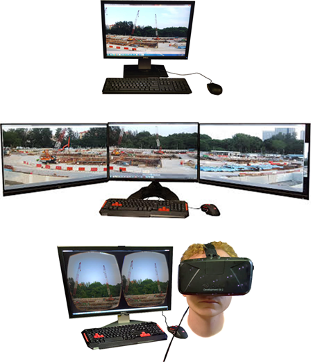
To give you a simple example of immersion, the figure below shows three setups that we used in a recent study on how different levels of immersion influence the feeling of being present (more below) in a remote meeting. We compared a standard desktop setting (the lowest level of immersion) with a three-monitor set up (medium level of immersion) against using an immersive headset (here the Oculus Rift). You can order these technologies as we have just done along a spectrum of immersiveness which then helps to design, for example, experiments to test whether or not being physically immersed has an effect, for example, on the subjective feeling of team membership. Imagine that instead, you are using Skype (or zoom, or any other video conferencing tool) but instead of staring at your single monitor, the other person is streaming a 360-degree video directly into your VR HMD.
In contrast, the nature of presence in and of itself is highly subjective, making it hard to distinguish from concepts like immersion (well, we just did). The sense of presence is indeed the subjective sense of being in the virtual environment (Bulu, 2012). Many smart people have thought about this and to make things more fun have developed further distinctions such as spatial presence, co-presence, and telepresence. Sense of presence seems to be, interestingly enough, related to immersion and several studies have shown that immersive capabilities of technology, specifically VR technology, impact the subjective feeling of presence (Balakrishnan & Sundar, 2011). Therefore, different configurations of technology to increase immersive capabilities should increase the sense of presence experienced by a user (well, it is a plausible hypothesis).
The relationship between immersion and presence forms at the point when user attention is focused (or absorbed) enough to allow for involvement in the content to become engaged with the digital environment (Oprean, 2014). This relationship allows for a clear distinction between immersion and presence while enabling a framework for measuring the influence of one on the other. On similar grounds, and as was previously mentioned, Witmer and Singer (1988) argue that both immersion and involvement are prerequisites for experiencing presence in a virtual environment. Involvement from their perspective is defined as “a psychological state experienced as a consequence of focusing one's energy and attention on a coherent set of stimuli or meaningfully related activities and events” (ibid, page 227), and also related to other concepts similar to engagement such as the “flow state” introduced by Csikszentmihalyi (1992).
Presence is a large and heavily measured construct in research on spatial experiences. The construct of presence consists of a number of dimensions specific to different contextual purposes: spatial, co-, tele-, social, etc. Each dimension of presence is considered with the same foundational meaning: that a user feels ‘present’ within a given medium, perceiving the virtual content (Steuer, 1992). The different dimensions, however, help to further distinguish the context or situation in which presence occurs.
The dimensions of presence cover a range of contextually different concepts that are often used interchangeably (Zhao, 2003). Telepresence distinguishes itself through its original context, teleoperation work (Sheridan, 1992). Steuer (1992) defines telepresence as distinguishable from presence by suggesting it refers to the experience of a secondary, such as virtual, environment through a communication medium. Taking both of these distinctions into account, telepresence, as related to its context of teleoperation, suggests that perceptions relate to experiencing a virtual environment in which work (i.e., interaction) can occur through a communication medium. This definition relates to the development occurring in collaboration research with telepresence systems; systems meant to mediate a sense of presence to enable work on tasks, individually or collectively.
Co-presence is similar, yet a different dimension of presence, than telepresence. Nowak and Biocca (2003) note the distinctions between telepresence and co-presence as pertaining to connection with others. Whereas telepresence can occur without other individual’s involvement, co-presence is dependent on another human being present to connect with through a communication medium. This human connection is what distinguishes co-presence from telepresence, a focus on a human-human relation (Zhao, 2003).
Social presence, another dimension of presence, has a similar definition to co-presence but requires a group of humans to connect with (Nowak & Biocca, 2003). Gunawardena and Zittle (1997) further the definition of social presence stating it is the degree of perceived realness of a person in a mediated communication. This perception of realness is dependent on two concepts: intimacy and immediacy (Gunawardena & Zittle, 1997).
Spatial presence builds on the foundational definition of presence, the feeling of being in an environment. Steuer (1992) notes that with any mediated communication there is overlap with the physical (real world) presence. Spatial presence there relates to the believability of being present within the mediated space, making spatial presence purely experiential.
In distinguishing the dimensions of presence, it becomes easier to establish factors which impact the level at which a user’s perception of being a part of a mediate space. In particular, such a distinction is necessary to understand the true implications of telepresence systems and how the initial sense of being a part of a mediated space impacts teamwork.
Interaction, in contrast, seems to be somewhat more straight forward and less troublesome to define than the concepts of immersion and presence. However, like with most things, once you dig deeper into it you will find that it is not so straight forward after all to make distinctions, especially when more than one modality is involved. Interaction can be broken down into dimensions such as navigation (whether an environment is navigable or not), does the interface allow for interaction and which modality is involved (gaze used often in cardboard environments versus haptic gloves), and human agency, which could relate to navigability but it also could be a measure of how much a user is able to interact with and/or manipulate a particular environment.
Instead of trying to further define these concepts we ask you to have a look at the Figure below. Most concepts we discussed can be arranged on a spectrum from high to low (especially immersion and interactivity). This distinction is useful when we think about different VR technologies.
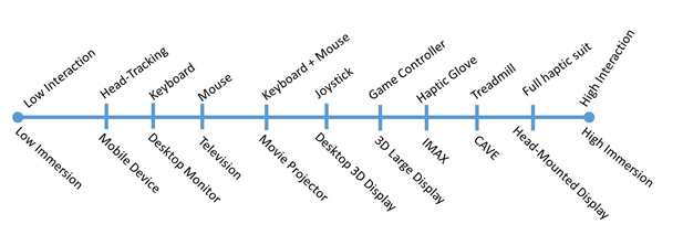
To summarize, this section provided a glimpse into the more academic discussion of how to conceptualize virtual reality. We briefly discussed important concepts such as immersion, presence, and interactivity and showed exemplarily how everyday use of the terms may interfere with their more academic definitions (although even academics get lots in these discussions). Distinguishing VR technologies along the dimensions of these concepts, for example, from high to low levels of immersion, is useful to a) talk about categories of technology rather than individual products; b) to start investigations of which technology might actually help in communicating or making decisions about space and place in the past, present, and future.
References
Balakrishnan, B., & Sundar, S. (2011). Where am I? How can I get there? Impact of navigability and narrative transportation on spatial presence. Human-Computer Interaction, 26(3), 161-204.
Bulu, S. T. (2012). Place presence, social presence, co-presence, and satisfaction in virtual worlds. Computers & Education, vol. 58, no. 1, pp. 154–161.
Csikszentmihalyi, M. & Csikszentmihalyi, I. S. (1992). Optimal experience: Psychological studies of flow in consciousness, Cambridge university press.
Choi, J. I., & Hannafin, M. (1995). Situated cognition and learning environments: Roles, structures, and implications for design. Educational technology research and development, 43(2), 53-69.
Gunawardena, C. N., & Zittle, F. J. (1997). Social presence as a predictor of satisfaction within a computer‐mediated conferencing environment. American journal of distance education, 11(3), 8-26.
Nowak, K. L., & Biocca, F. (2003). The effect of the agency and anthropomorphism on users' sense of telepresence, copresence, and social presence in virtual environments.Presence: Teleoperators & Virtual Environments, 12(5), 481-494. doi:10.1162/105474603322761289.
Oprean, D. (2014). Understanding the immersive experience: Examining the influence of visual immersiveness and interactivity on spatial experiences and understanding. Unpublished doctoral dissertation, University of Missouri.
Sheridan, T. B. (1992). Musings on telepresence and virtual presence.Presence: Teleoperators & Virtual Environments, 1(1), 120-126.
Slater, M. (1999). Measuring presence: A response to the Witmer and Singer presence questionnaire. Presence: Teleoperators and Virtual Environments,8(5), 560-565.
Steuer, J. (1992). Defining virtual reality: Dimensions determining telepresence. Journal of communication, 42(4), 73-93.
Witmer, B. G. & Singer, M. J. (1998). Measuring presence in virtual environments: A presence questionnaire, Presence 7 (3), 225–240.
Zhao, S. (2003). Toward a taxonomy of copresence. Presence: Teleoperators and Virtual Environments, 12(5), 445-455.
1.6 Examples
1.6 Examples
There is an almost infinite number of examples of VR content that is pushed on the market with new and exciting opportunities being added on a daily basis. We have selected a couple that we are looking at in a little more detail.
Google Cardboard / WITHIN
We have sent you a Google Cardboard. It is actually a slightly more advanced version than the standard one and it does help to adjust the distance between the lenses. If you are using Google Cardboard, there are many, many options to choose from that offer you content from Google itself but also other VR companies such as Within. You are strongly encouraged to explore content on your own! As one of the assignments we would like to give you, please watch the 360° video offered by Within called Clouds over Sidra. You can watch it either in the Cardboard viewer, or, if you prefer or have not received your viewer yet, you can also watch it on your phone without the viewer, or through other VR headsets, or on your computer via the web. The video Clouds over Sidra has been embedded below for your convenience.
Video: WITHIN 360° Video, Clouds Over Sidra (8:35)
We walked for days crossing the desert into Jordan. The week we left, my kite got stuck in a tree in our yard. I wonder if it is still there. I want it back.
My name is Sidra. I am 12 years old. I am in the fifth grade. I am from Syria and the Daraa Province in (inaudible city name). I have lived here in the Zaatari camp in Jordan for the last year and a half. I have a big family, three brothers one is a baby, he cries a lot. I asked my father if I cried when I was a baby and he says I did not. I think I was a stronger baby than my brother. [Music] We like to keep our bags and books clean and without rips. It is like a game to see who has the nicest books with no folds in the pages. [Music] I like cloudy days. I feel like I am under air cover, like a blanket. Our teachers sometimes pick students who do not place their hands to answer. So everybody raises their hand even if they do not know the answer. But I do my homework and I know the answer if she calls on me. [Music] There is a bakery not far from school. The smell of bread on the walk to class drives us mad sometimes. [Music] Some kids don't go to school. They want to wait until we are back home in Syria. I think it is silly to wait. How will they remember anything? And there is nothing better to do here anyway. Computers give the boys something to do. [Music] They say they are playing games but I don't know what they're doing because they won't let girls play on the computers. I don't understand computer games [Music] or boys. Many of the men say they exercise because they want to be strong for the journey home. But I think they just like how they look in the mirror. A lot of them make funny sounds when they lift the weights. [Music] The younger boys are not allowed in the gym so they wrestle or they try to wrestle.[Music] Even after everything, boys still like to fight. [Music] We have to play football quickly because there are so many kids waiting to play, especially now. Unlike home, here in Zaatari girls can play football too. That makes us happy. [Music] My mother makes sure we are all together for dinner. I still love her food even if she doesn't have the spices she used to. [Music] [Applause] There are more kids in Zaatari than adults right now. Sometimes I think we are the ones in charge. [Music] [Music] I think being here for a year and a half has been long enough. [Music] I will not be 12 forever and I will not be in Zaatari forever. My teacher says the clouds moving over us also came here from Syria. Someday the clouds and me are going to turn around and go back home. [Music]
To watch this 360 video you can click on the video, visit WITHIN [21] or download and use the WITHIN app for a cardboard experience (recommended).
When watching the video, especially in the Cardboard / immersive headset option, take note on a couple of things:
- How does filming a 360° video change how you follow the storyline of the video. Take note of aspects of the video that may or may not be unintentional.
- What is the role that audio plays in watching the video and providing guidance on what to focus on (it is best to use headphones).
- What does being immersed add to the video, how do your attention and your connection to the place change?
- Did you try watching the video standing? I personally feel that it adds to my sense of place (and the camera was at a somewhat higher viewpoint).
- Anything else?
Google Expeditions
All major technology companies are investing heavily in 3D/VR technology. Google’s Expeditions Pioneer Program is one example. Expeditions is a professional virtual reality platform that is built for the classroom. Google has teamed up with teachers and content partners from around the world to create more than 150 engaging journeys - making it easy to immerse students in entirely new experiences. Feel free to explore. This tool is geared toward classroom experiences but may offer some insights into how geography education may change in the future. Maybe geography will return to the K12 curriculum?

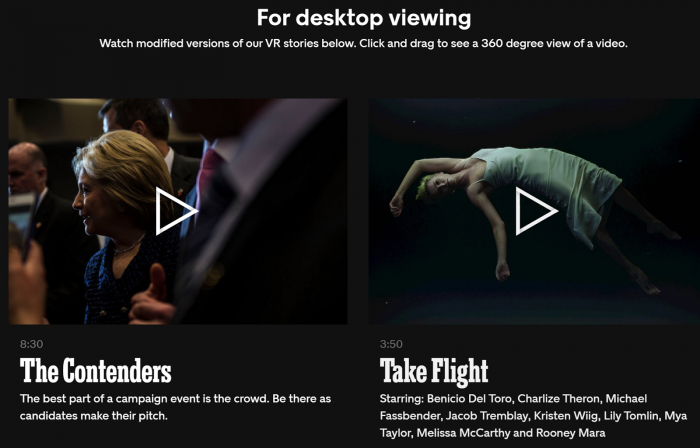
New York Times Virtual Reality (NYT VR)
The New York Times, as one of the first major news providers, has created an NYT VR app [23] that can be downloaded for both Apple and Android platforms.
The app can be used in combination with Google Cardboard or any other viewer that accepts your smartphone. By now all major news corporations have 360-degree video offerings.
Graded Assignment: 3D/VR Project Review
Task
Find two examples of 3D/VR projects other than the ones discussed above and write a short paragraph about each. In this exercise, you should select projects that you find exciting and reflect on why you think they will change the geospatial sciences, how information is communicated or made accessible, how people will be able to understand places across space and time differently, etc. Projects do not have to be movies but can address any 3D/VR topics somewhat related to geospatial.
Due Date
Please upload your assignment by 11:59 p.m. Tuesday.
Guidelines and Writing Rubric
In your reflection make sure that you answer the following questions:
- Which aspects of the geospatial sciences will be affected most?
- There are many other aspects to consider such as communicating and sharing health information, fostering social engagement, communicating climate change. Which field do you think will be affected most?
- Does the length of the videos play a role? How long can you watch movies as immersive experiences?
| Criteria | Full Credit | Half Credit | No Credit | Possible Points |
|---|---|---|---|---|
| Examples provided are different from course examples. | 2 pts | 1 pts | 0 pts | 2 pts |
| Link to the website/app and description of the platform through which the student experienced the movie is provided. | 1 pts | .5 pts | 0 pts | 1 pts |
| Reflection is well thought out, researched, organized, and answers the questions posed in the lesson. | 4 pts | 2 pts | 0 pts | 4 pts |
| The document is grammatically correct, typo-free and cited where necessary. | 1 pts | .5 pts | 0 pts | 1 pts |
| Total Points: 8 |
Summary and Tasks Reminder
Summary and Tasks Reminder
In this introductory lesson, we went through a plethora of topics contributing to the excitement and opportunities that 3D modeling and VR have for the geospatial sciences but also for society at large. It is a legitimate question whether or not communication about places through time and space will be the same after 3D/VR technologies have entered mainstream fully. There are a lot of opportunities and there are still a lot of unknowns. The lack of content, despite a booming market, has been identified as the main obstacle for VR; geospatial sciences through 3D modeling developments are in an excellent position to play a key role as content providers and also benefit from a booming VR market in return. We are at the verge of a new era of information systems that will allow for the development of immersive experiences alongside classic visualization techniques.
In the next lesson, we will talk more about the different workflows that are in place or developing that allow for the creation of 3D content.
Reminder - Complete all of the Lesson 1 tasks!
You have reached the end of Lesson 1! Double-check the to-do list on the Lesson 1 Overview page to make sure you have completed all of the activities listed there before you begin Lesson 2.
Lesson 2: 3D Modeling and VR Workflows
Overview
Overview
As discussed in Lesson 1, 3D modeling and the availability of 3D data are going mainstream. Technology, while it has always developed as part of society for thousands of years, has now reached a level of maturity that allows non-experts to make substantial contributions in several fields. 3D modeling and VR are at a point where cartography was 20 years ago when map-making was placed into the hands of the masses (for better or worse). The workflows that we are discussing in this lesson are examples of how affordable and accessible 3D modeling has become but also provide insights into higher-end solutions. As with all aspects of this course, we will only scratch the surface of a number of possibilities and what was true at the beginning of the course may even be replaced by newer technologies, better algorithms, and lower-cost solutions at the end. We are living in exciting times.
Learning Outcomes
By the end of this lesson, you should be able to:
- Compare input modalities such as sensed data versus modeling
- Discuss options for using remotely sensed data such as LiDAR
- Compare modeling platforms such as CityEngine, AutoCAD, SketchUp
- Discuss options on how to interact with 3D models
- Define the concept of a game engine such as Unity3D
- Discuss hardware available for interacting with 3D models in VR
Lesson Roadmap
| To Read |
|
|---|---|
| To Do |
|
Questions?
If you have any questions, please post them to our "General and Technical Questions" discussion (not e-mail). I will check that discussion forum daily to respond. While you are there, feel free to post your own responses if you, too, are able to help out a classmate.
2.1 Prerequisite: The Level of Detail
2.1 Prerequisite: The Level of Detail
The Figure below shows different models of Penn State campus and Penn State buildings, respectively. It can easily be imagined that the level of detail of the model on the top may suffice for certain planning or analysis purposes, but that a detailed model (bottom) is required for applications such as architectural planning and engineering. The level of detail is not easy to define for 3D models and there is not a single standard for the "right" level of detail of 3D models. There are related discussions in cartography such as what is a schematic map (or are all maps schematic?). The level of detail is important though as it has implications on aspects such as performance, for example, in virtual reality environments. While there is not a direct correspondence between level of detail and polygon count (the number of individual surfaces that need to be processed), it can be easily imagined that complex models require a lot of computing power to interact with while, simple models allow for keeping up sufficient frame rates, for example, in immersive VR experiences (see Lesson 8 and 9). Interestingly, in many planning scenarios, people may decide to have more than one version of a model, one with a low and one with a higher level of detail in order to use them flexibly in different applications. Unlike map generalizations, there are only a few approaches that allow for 3D model generalization.
Below are examples of different levels of detail of 3D models.
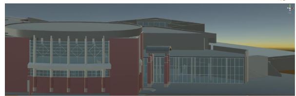
It is advisable to think about the level of detail that one requires before starting the modeling process. It is still the case that the more detail you need, the higher the cost will be in terms of time, software product, and computing resources.
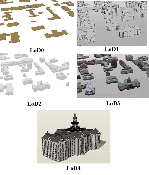
A good starting point for thinking of the levels of detail of 3D models is an approach referred to as CityGML [27] that envisioned to standardize 3D models. While the active development of CityGML has slowed down, its classification of levels of detail provides a good basis for discussion. CityGML identifies five levels of detail based on accuracy and minimal dimensions of objects that can roughly be characterized as follows (see also Figure 2.1.2, and Kolbe et al. 2005):
- LoD0: essentially a digital terrain model with potentially 2.5D information.
- LoD1: the positional and height accuracy of points may be 5m or less, while all objects with a footprint of at least 6m by 6m have to be considered.
- LoD2: this level requires positional accuracy of 2m, while the height accuracy is 1m. In this LoD, all objects with a footprint of at least 4m by 4m have to be considered.
- LoD3: Both height and positional accuracy are 0.5m, and the minimal footprint is 2m by 2m.
- LoD4: Both height and positional accuracy are 0.2m.
As this brief discussion illustrates, the level of detail has substantial consequences on the visual appearance of 3D models, as well as on cost and efficiency. Cost is associated with time but also actual software products (e.g., high-end CAD programs for a higher level of detail; procedural rule software for a lower or medium level of detail). Efficiency is related to the computing power necessary to turn a 3D model into a smooth interactive experience.
2.2 Workflows for 3D Model Construction
2.2 Workflows for 3D Model Construction
Overview
Creating 3D models of buildings, artifacts, and cities enable potentially better decision making, education, and planning in many fields such as archeology, architecture, urban sciences, and geography. Creating virtual cities, for example, allows for presenting scenarios of future development plans with more realism to assess their feasibility and plan their implementation. There are informational values in creating virtual cities including better communication with non-technical audiences that is, the community. Additionally, there are new approaches in 3D analysis, for instance, dealing with views, shadows, the reflected heat of building blocks, and the calculation of hours of sunshine.
3D modeling is the process of digitally representing the 3D surface of an object. However, the model is usually rendered to be displayed as a 2D image on a computer screen. Experiencing the model in 3D can be achieved using 3D printing devices or presenting it in a virtual reality (VR) environment. There are different methods of 3D model construction and methods of accessing them. Figure 2.2.1 provides an overview of a couple of options for both creating and accessing 3D models that we will discuss in more detail later in this lesson. Many of the tools that are shown in the figure will be introduced throughout the course while others are challenging to work within an online environment.
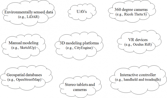
The Figure above just name a couple of examples for efficiently collecting and accessing 3D data and information. A booming market for 3D technologies such as photogrammetry, 360-degree cameras, scanning tablets, but also the efficient use of existing data such as Open Street Map, have made content creation for 3D environments accessible to a wide audience. At the same time, VR technology is going mainstream with international companies such as Facebook™ or HTC™ weeding out roadblocks such as cyber/motion sickness.
2.3 Manual Static 3D Modeling
2.3 Manual Static 3D Modeling
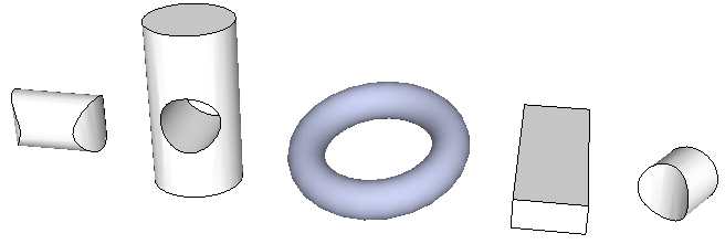
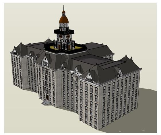
To give you an idea of modeling, let us first consider modeling by hand. In this case, a model of an object, whether existent or not in the past, present, or future is constructed by a human using software modeling tools manually. Creating 3D models manually can be done using software such as SketchUp (see Lesson 3), Maya, 3Ds Max, Blender and Cinema 4D, or any one of a number of software that exists for 3D modeling. There are two main techniques in manually creating 3D models: solid modeling and shell modeling. Solid modeling often uses CSG (constructive solid geometry) techniques. CAD packages such as Rhino, SolidWorks, and SketchUp are considered solid modeling platforms. Complex 3D models can be created with the use of solid geometries. The Figure below shows a couple of solid geometries that are used to create potentially very complex models. An example of a complete 3D model is shown below: a model of the historic Old Main created as part of Geography 497 in Spring 2016.
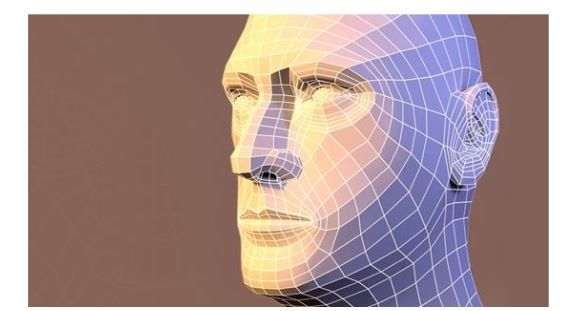
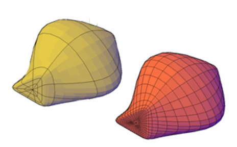
Shell modeling only represents the surface of an object. These types of models are easier to visualize and work with. An example of shell modeling is the use of polygon meshes consisting of a collection of triangles or any other type of convex polygon (from other geography lessons on interpolation you might be familiar with triangulation). Polygon meshes only represent the exterior of a model. To make the model smoother and more realistic, a method called tessellation can be used to break down the polygon meshes to higher resolution poly meshes. Programs such as Maya, 3D Studio Max, and Blender all utilize different methods of working with polygonal meshes.
While there is a distinct difference between CSG and shell modeling, many of the programs mentioned and even those that were not, provide support for both types in a limited capacity. Understanding what type of modeling best fits your project needs helps with choosing the best software for 3D modeling tasks.
2.4 Data-Driven Modeling
2.4 Data-Driven Modeling
Introduction
Shell modeling can be achieved based on photographs/ aerial imagery or scanning model geometry from the real world using, for example, laser scanners. In this section, we will learn about A) Reality modeling and B) Scanning: Remotely Sensed Data such as LiDAR Point Clouds.
A. Reality Modeling
A. Reality Modeling
Reality models provide real-world context using aerial imagery and/or photographs. Technologies like 3D imaging and photogrammetry with the use of UAVs (unmanned aerial vehicle) provide these images to be used in software for converting a 2D map to a 3D model. Examples of software for this approach are ContextCapture by Bentley and VUE, PlantFactory, Ozon, Drone2Map by ESRI, or CarbonScatter by E-on.
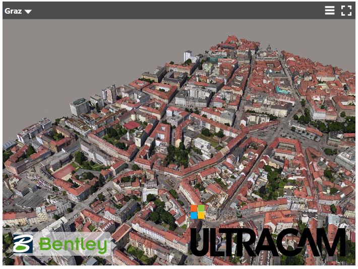


LumenRT, for example, is an E-on software licensed by Bentley. It can create real-time immersive experiences. It presents a combination of tools that create ultra-high-definition videos and photographic images for 3D projects.
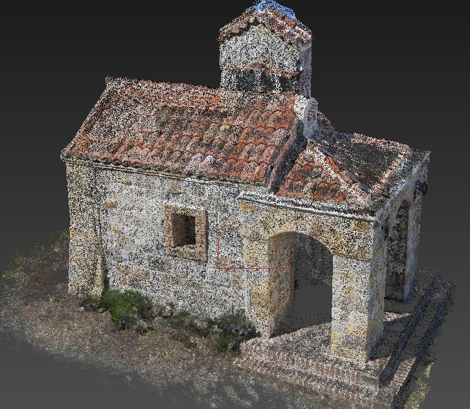
One of the methods for creating 3D structures from 2D images is structure from motion (SFM) photogrammetry. There are several software packages for creating and reconstructing three-dimensional structures: Agisoft, VisualSFM, CMPMVS, Meshlab, and Blender. For instance, Aibotix GmbH has created a 3D model of Castle Spangenberg in Germany using a combined mapping workflow. Data was collected with multirotor UAV Aibot X6 and ground surveying equipment. The collected data was then processed with the help of Agisoft PhotoScan.
Video: Drone surveying of Castle Spangenberg with the UAV Aibot X6 (2:07) This is video is not narrated, music only.
B. Scanning: Remotely Sensed Data Such as LiDAR Point Clouds
B. Scanning: Remotely Sensed Data Such as LiDAR Point Clouds
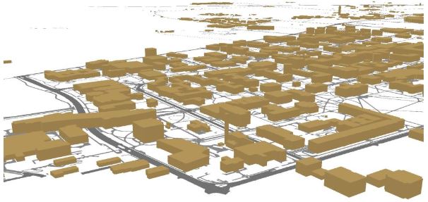
Data-driven modeling can also be achieved through point clouds to render exterior surfaces. A point cloud can be obtained by laser scanning. LiDAR as a system of collecting point clouds is explicitly explained in this section. The fact that point clouds do not contain any type of geometry is an important characteristic in modeling because they do not change the appearance or respond to scene lighting by default. They enable the designer to incorporate realistic 3D objects without having to model them. The drawback is that the objects are not editable with traditional techniques (Autodesk) [35]. Software that processes and supports point clouds as input data are Potree, Rhino, the Autodesk products, Blender, Pointools, Mathworks, and Meshlab.
LiDAR is an active remotely sensed method of collecting information. It uses active sensors that have their own source of light or illumination. There are two types of LiDAR systems: airborne and terrestrial scanning systems. Airborne Laser scanning known as LiDAR (Light Detection and Ranging) is a remote sensing technique that measures variable distances to the earth using a pulsed laser. Aircraft, helicopters, or UAVs (unmanned aerial vehicle) such as drones are common platforms for collecting LiDAR data. The LiDAR systems collect x, y, and z data at predefined intervals.
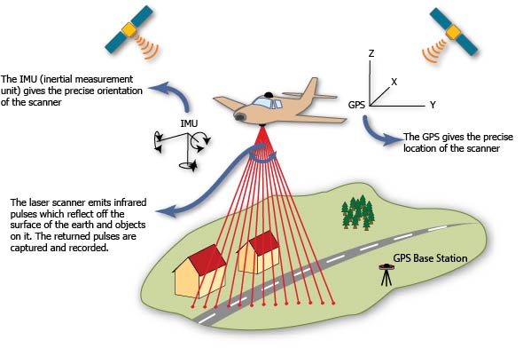
Based on LiDAR data, high-quality elevation models can be created. For instance, the airborne LiDAR data collected for the Penn State campus contains points at 25 cm intervals. LiDAR returns two types of elevation models: (1) a first return surface including anything above the ground such as buildings and canopy, it is referred to as DSM (digital surface model) and, (2) The ground or bare earth which is referred to as DEM (digital elevation model), it contains topography.
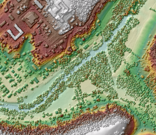
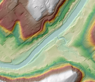
The workflows of DEM and DSM creation are outside of the scope of this course. Using these elevation models, buildings, trees, and roads can be extracted from the LiDAR data with elevation information. High-resolution LiDAR data can provide more precise information regarding height. Most GIS systems such as LiDAR analyst, LAStools, and Lp360 made the data extraction automatic or semi-automatic. For instance, the extracted information of buildings contains roof sections, shape size and estimated height of buildings. To detect more accurate height information, facade geometry, and textures, extra systems such as terrestrial laser scanning and photogrammetry should be incorporated into the model. Terrestrial or ground-based laser scanning (Terrestrial LiDAR) is used for high accuracy feature reconstruction. With a combination of airborne and terrestrial LiDAR more realistic 3D models can be created.
The following image shows how a LiDAR point cloud using an airborne LiDAR system can be colorized with RGB values from a digital aerial photo to produce a realistic 3D oblique view. There are numerous papers on developing algorithms that can automate the process of 3D modeling using LiDAR data and aerial photography.
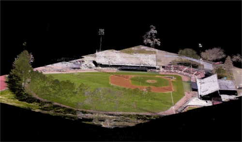
2.5 Procedural Modeling
2.5 Procedural Modeling
For realistic scenes, more complex models are needed. Creating these types of models can be tedious. One solution is to construct 3D models or textures algorithmically. Procedural modeling has been used in some techniques in computer graphics to create 3D models based on sets of rules. Procedural computing is the process of creating data algorithmically instead of manually. In computer graphics, it is used for creating textures. Mostly, procedural rules are used for creating complex models such as plants, buildings, cities or landscapes which require more specialized tools and are time-consuming for a person to build. With procedural rules, developing complicated models is simplified through repeating processes, automatic generation, and if necessary randomization.
One of the methods in procedural modeling is the use of fractals (fractal geometry) to create self-similar objects. Fractals are complex geometries with never-ending patterns. In other words, they can have infinite patterns at different resolutions. This type of approach is useful in creating natural models such as plants, clouds, coastlines, and landscapes. For instance, a tree can be automatically created based on branching properties and type of leaves. Then a forest can be generated automatically by tree randomization.
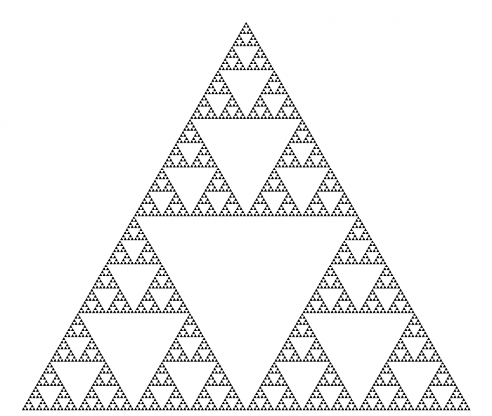
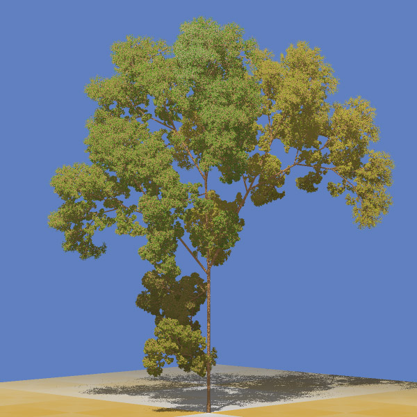
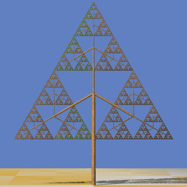
Another method in procedural modeling is generating models based on grammars. Grammar-based modeling defines rules that repeatedly can produce more details and create finer models as in the image below. Tree shape data structure or model hierarchy plays an important role in grammar-based modeling both in terms of programming efficiency and adding more details to a shape.

Instances of procedural modeling platforms are ESRI CityEngine, Vue, and Fugu. Xfrog is a component that can be added to a different platform such as Maya and CAD to build plants, organic shapes or abstract objects.
Procedural modeling will be the topic of Lesson 4.
2.6 3D and VR Application Building Workflows
2.6 3D and VR Application Building Workflows
Typically, 3D models are created with a concrete final application or product in mind. This could be presentational material for a web site, a standalone 3D application like a virtual city tour or computer game, a VR application intended to be run on one of the different consumer VR platforms available today, or some spatial analysis to be performed with the created model to support future decision making, to name just a few examples. In many of these application scenarios, a user is supposed to interact with the created 3D model. Interaction options range from passively observing the model, for example, as an image, animation, or movie, over being able to navigate within the model, to being able to actively measure and manipulate parts of the model. Usually, the workflows to create the final product require many steps and involve several different software tools, including 3D modeling software, 3D application building software like game engines, 3D spatial analysis tools, 3D presentation tools and platforms, and different target platforms and devices.
The figure below illustrates how 3D application building workflows could look like on a general level: The workflow potentially starts with some measured or otherwise obtained input data that is imported into one or more 3D modeling tools, keeping in mind such input could also simply be sketches or single photos. Using 3D modeling tools, 3D models are created manually or using automatic computational methods, or a combination of both. The created models can then either be used as input for some spatial analysis tools, directly used with some presentational tools, for example, to embed an animated version of the model on a web page, or the models are exported/imported into a 3D application building software, which typically are game engines such as Unity3D or the Unreal engine, to build a 3D application around the models. The result from the 3D application building work can again be a static output like a movie to be used as presentation material, or an interactive 3D or VR application built for one of many available target platforms or devices, for example, a Windows/macOS/Linux stand-alone 3D application, an application for a mobile device (for instance, Android or iOS-based), or a VR application for one of the many available VR devices. The figure below is an idealization in that the workflows in reality typically are not as linear as indicated by the arrows. Often it is required to go back one or more steps, for instance from the 3D application building phase to the 3D modeling phase, to modify the previous outputs based on experiences made or problems encountered in later phases. It is also possible that the project is conducted by working on several stages in parallel, such as creating multiple levels of detail (LoD) 3D models to work with the intended platform. Moreover, while we list example software for the different areas in the figure, these lists are definitely not exhaustive and, in addition, existing 3D software often covers several of these areas. For instance, 3D modeling software often allows for creating animation such as camera flights through a scene, or in the case of Esri's CityEngine/ArcGIS Pro allow for running different analyses within the constructed model.
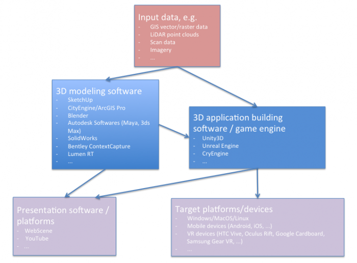
A schematic diagram outlines the following information (in summary):
- Input data (in a variety of formats) imported into either a 3D modeling software or a 3D application building software such as a game engine.
- In 3D modeling software, 3D models are created either manually or automatically based on computational methods The resulting models could be either directly used for visualization (i.e. on the web) or imported into 3D application building software such as Unity3D for more elaborate functionalities.
- The application made from game engines (e.g. Unity 3D) can be deployed on both web and a variety of platforms including VR headsets.
- Depending on the application and the deployment platform attributes of models such as levels of detail (LoD) can be manipulated
A 3D modeling project can also aim at several or even many target formats and platforms simultaneously. For instance, for the PSU campus modeling project, that we are using as an example in this course, the goal could be to produce (a) images and animated models of individual buildings for a web presentation, (b) a 360° movie of a camera flight over the campus that can be shared via YouTube and also be watched in 3D with the Google Cardboard, (c) a standalone Windows application showing the same camera flight as in the 360° video, (d) a similar standalone application for Android-based smartphone but one where the user can look around by tilting and panning the phone, and (e) VR applications for the Oculus Rift and HTC Vive where the user can observe and walk around in the model.
The next figure illustrates the concrete workflow for this project (again in an idealized linear order) with the actual software tools used and providing more details on the interfaces between the different stages. The main input data for the campus model is extracted from Airborne LiDAR point clouds. Based on this data, building footprints, buildings, and trees height, Digital Elevation Model (DEM) are extracted. Roads (streets and walkways) are 2D shapefiles received from the Office of Physical Plant at PSU. Roof shapes and tree types information are collected based on surveys. DEM which is in raster format and other data that are in vector format (polygons, lines, and points) are imported to CityEngine which is a generation engine for creating procedural models. Procedural modeling using CityEngine will be explained in more detail in Lesson 4. The result of the procedural model can be shared on the web as an ArcGIS Web Scene for visualization and presentation. It can also be exported to 3D/VR application building software.
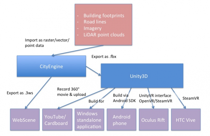
A schematic diagram outlines the following information (in summary):
- Extraction of mode data from LiDAR point cloud.
- Digital Elevation Model (DEM) are imported into CityEngine for generation of procedural models.
- Result can be shared on the web as an ArcGIS Web Scene, or exported to 3D/VR application building software such as Unity3D.
The 3D/VR application building software we are going to use in this course will be the Unity3D game engine (Lessons 8 and 9). A game engine is a software system for creating video games, often both 2D and 3D games. However, the maturity and flexibility of this software allows for implementing a wide range of 3D and now VR applications. The entertainment industry has always been one of the driving forces of 3D and VR technology, so it is probably not surprising that some of the most advanced software tools to build 3D applications come from this area. A game engine typically comprises an engine to render 3D scenes in high-quality, an engine for showing animations, a physics and collision detection engine as well as additional systems for sound, networking, etc. Hence, it saves the game/VR developer from having to implement these sophisticated algorithmic software modules him- or herself. In addition, game engines usually have a visual editor that allows for producing games (or other 3D application) even by non-programmers via mouse interaction rather than coding, as well as a scripting interface in which all required game code can be written and integrated with the rest of the game engine or in which tedious scene building tasks can be automated.
Unity can import 3D models in many formats. A model created with CityEngine can, for instance, be exported and then imported into Unity using the Autodesk FBX [42]format. SketchUp models can, for instance, be imported as COLLADA .dae [43] files. In the context of our PSU campus project, Unity3D then allows us to do things like creating a pre-programmed camera flight over the scene, placing a user-controlled avatar in the scene, and implementing dynamics (e.g., think of day/night and weather changes, computer-controlled moving object like humans or cars) and user interactions (e.g., teleporting to different locations, scene changes like when entering a building, retrieving additional information like building information or route directions, and so on).
The different extensions and plugins available for Unity allow for recording images and movies of an (animated) scene as well aw to build final 3D applications for all common operating systems and many VR devices. For instance, you will learn how to record 360° images for each frame of a camera flight over the campus in Unity. These images can be stitched together to form a 360° movie that can be uploaded to YouTube and from there be watched in 3D on a smartphone by using the Google Cardboard VR device (or on any other VR device able to work with 360° movies directly). You will also learn how to build a standalone application from a 3D project that can be run on Windows outside of the Unity editor. Another way to deploy the campus project is by building a standalone app for an Android-based phone. Unity has the built-in functionality to produce Android apps and push them to a connected phone via the Android SDK (e.g., coming with Android Studio [44]). Finally, Unity can interface with VR devices such as the Oculus Rift and HTC Vive to directly have the scene rendered to the head-mounted displays of these devices, interact with the respective controllers, etc. There exist several Unity extensions for such VR devices and the VR support is continuously improved and streamlined with each new release of Unity. SteamVR [45] and the OVR [46], and VRTK [47]for Unity currently take a central role for building Unity applications for the Rift and the Vive.
2.7 Photogrammetry
2.7 Photogrammetry
We have briefly mentioned photogrammetry and several of you have found related examples in the previous week. Amazing things are happening in the area of photogrammetry! Photogrammetry, for those who are not familiar with it, can be loosely defined as the art and science of measuring in photos. For the case of 3D modeling this has vast applications:
- Imagine that a house you would like to model no longer exists in the real world but you still have access to images through, for example, a library. Penn State and its main campus have undergone drastic changes in the last 170 years. Naturally, not all buildings that were on campus are still there. Penn State’s library has taken on the task to preserve some of the knowledge we have about previous states of the campus and has created digital archives for images but also maps. Here is an example: Maps: State College Change Through Time [48].
- Imagine that you are an archeologist and that you are interested in preserving the heritage of an ancient site. There are high-level approaches through companies like Bentley, who recently modeled the Penn State Campus but they are really expensive and may or may not be necessary for your purposes. A substantially less expensive approach that nonetheless provides you with a 3D model of a site can be accomplished with so-called structure from motion mapping. Below is an example from a project of the University of Ghent in Belgium and Penn State's Obelisk that a ChoroPhronesis member (Jiayan Zhao) created.
Example: The Mayan site of Edzna in Campeche (Mexico)
Example: Penn State's Obelisk
Photogrammetry has traditionally been within the field of geodesy and remote sensing, but its applications are becoming ubiquitous. Originally, it was used to measure distances, define the extent of areas, and essentially identify and geo-locate terrain features with the purpose to complement databases and/or to create maps.
Required Reading Assignment
To give you an example of a recent approach that uses Google Earth images for 3D modeling, we would like you to read the following article.
Rapid 3D Modeling Using Photogrammetry Applied to Google Earth [24] by Jorge Chen and Keith C. Clarke.
As you read, please keep in mind the following questions:
- Which locations did the authors use for their study?
- For what reason did the authors use LiDAR?
- What do you think of the outcome?
- Can you think of ways to improve the resulting 3D model?
Tasks and Deliverables
Tasks and Deliverables
Assignment
This assignment has two tasks.
Task 1: Find an article
Please find an article that describes a 3D/VR workflow. Make sure that the article has been peer-reviewed. Determine whether the entire article was peer-reviewed (most journals are) or just the abstract was peer-reviewed (as some conference proceedings may be). Either download the article, if that is an option or save the URL to the article for use in the second half of your assignment.
Task 2: Write a review on the article
Once you have decided upon an article, write a 4-6 sentence paragraph detailing why you selected this particular article and what you like about it. Make sure that you explain how the article adds value to GIS and/or other sciences. Some reasons you might select an article are because it discusses advances in GIS and/or other disciplines you think are important, it describes its topic clearly, it is informative and would allow you to implement a workflow yourself, or it gets high marks because it is just cool. In your document, provide a full reference for the article (using APA style) and a link to the article or provide an electronic copy of the document. Below are two examples of complete references.
- Li, R., & Klippel, A. (2016). Wayfinding behaviors in complex buildings: The impact of environmental legibility and familiarity. Environment and Behavior, 43(3), 482–510. doi:10.1177/0013916514550243
- Sparks, K., Klippel, A., Wallgrün, J. O., & Mark, D. M. (2015). Citizen science land cover classification based on ground and aerial imagery. In S. I. Fabrikant, M. Raubal, M. Bertolotto, C. Davies, S. M. Freundschuh, & S. Bell (Eds.), Proceedings, Conference on Spatial Information Theory (COSIT 2015), Santa Fe, NM, USA, Oct. 12-16, 2015 (pp. 289–305). Berlin: Springer.
Due Date
This assignment is due on Tuesday at 11:59 p.m.
Submitting Your Deliverable
Please submit your completed deliverable to the Lesson 2 (Article and Review) Assignment.
Grading Rubric
| Criteria | Full Credit | Half Credit | No Credit | Possible Points |
|---|---|---|---|---|
| Article selected is peer-reviewed, the type of peer review is indicated, the link to the article (or file) is provided, and full reference is present. | 5 pts | 2.5 pts | 0 pts | 5 pts |
| Write up clearly communicates how the article adds value to GIS or other scientific fields. | 4 pts | 2 pts | 0 pts | 4 pts |
| Write up is well thought out, researched, organized, contains some technical specifications and clearly communicates why student selected and likes the article. | 5 pts | 2.5 pts | 0 pts | 5 pts |
| The document is grammatically correct, typo-free, and cited where necessary. | 1 pts | .5 pts | 0 pts | 1 pts |
|
Total Points: 15 |
Summary and Tasks Reminder
Summary and Tasks Reminder
This lesson hopefully conveyed how creative and exciting the developments are that allow for the creation of 3D models and VR content. There are classic approaches coming out of photogrammetry, such as structure from motion mapping (SFM), that existed for a long time but only recently reached a mature level. There are creative minds that combine different technologies such as Google Earth and SFM to simulate fly overs and much more. The article we integrated by Chen and Clarke was only been presented in September 2016, so very recent. As we have been successfully using it in our own work, we thought we would integrate it into this lesson. It is a really fast-moving field and if anything, many products will become even more mature over the next years with numerous start-ups pushing into the market.
Reminder - Complete all of the Lesson 2 tasks!
You have reached the end of Lesson 2! Double-check the to-do list on the Lesson 2 Overview page to make sure you have completed all of the activities listed there before you begin Lesson 3.
Lesson 3: Hands-On Modeling Using SketchUp
Overview
Overview
SketchUp is one of the most versatile and easiest to learn 3D modeling tools on the market. It offers an excellent balance between functionality and quality on the one hand and ease of use on the other. It allows users with relatively little experience to create exceptional 3D models of almost anything. SketchUp is not tied to a single domain (e.g., architecture) but you will find that every discipline and industry in need of 3D models is using SketchUp: architects, landscape architect, architectural engineers, interior designers, construction professionals, urban planners, woodworkers, artists, sculptors, mapmakers, historians, 3D game designers, and more. SketchUp was part of the Google™ family but is now owned by Trimble™. We will only scratch the surface of this versatile modeling tool that through its warehouse for models (assets) from users and companies might become one of your favorite tools if you are planning to create building models of the past, present, or future, if you want to design room interiors, model your dream car, or, through its large expansion opportunities you might be interested in creating solutions for augmented reality. One of our colleagues said that he treats SketchUp like Minecraft™ but instead of largely using blocks you have every geometric form under the sun at your disposal.
While geographers are only slowly yet steadily entering the world of 3D, certainly one of the biggest trends at recent ESRI user conferences, the results of using SketchUp in our residential courses are quite remarkable. Here are some models that some students have created after a weeklong introduction. More models and more information can be found on our websites (Sketchfab [54]; Sites [55]).
The model below shows Old Main, the landmark building of Penn State, in its historic form (before 1930). The model has been created by Matt Diaz and curated by Niloufar Kiromasi, both interns at ChoroPhronesis (Summer 2016). Modeling has been possible thanks to an ongoing collaboration with the Penn State Library who is offering historic images and floor plans for buildings that do not exist anymore on campus. Our efforts make a contribution to what has come known as cultural heritage research, in our case, we are working toward a strategy to recreate environments long gone. If you would like to know more about Old Main’s history, visit Penn State's Historic Old Main [56].
Click the image below to move the building around using your mouse, stylus, or finger on the screen. If you want to view the building using your Cardboard Viewer, go to Sketchfab Penn State University 1922: Old Main [57].
SketchUp model of Old Main [57]
Learning Outcomes
By the end of this lesson, you should be able to:
- Set up your workspace in SketchUp
- Draw basic 2D shapes such as rectangles, triangles, cylinders in SketchUp
- Turn 2D shapes into 3D objects in SketchUp
- Differentiate between inference, groups, and components
- Use textures in SketchUp
- Optimize your model
- Create your own building models in SketchUp
- Export your model from SketchUp and share it with the world via Sketchfab (optional)
Lesson Roadmap
| To Read |
|
|---|---|
| To Do |
|
Questions?
If you have any questions, please post them to our "General and Technical Questions" discussion (not e-mail). I will check that discussion forum daily to respond. While you are there, feel free to post your own responses if you, too, are able to help out a classmate.
3.1 Start Modeling
3.1 Start Modeling
I would like to offer you a word of caution: not everyone is a modeler. That does not mean and should not mean that you cannot create a beautiful model (or pass this lesson!). It simply means that some people develop a love for creating models while others really do not like it. One piece of advice that works on almost everything in these situations is to practice, practice, and practice. We will start off everyone on the right foot by going through several tutorials; we will encourage you to practice (and practice, and practice). We will also request a two-tier exercise at the end acknowledging that this is a 2-week max exercise and not a course on SketchUp. However, there is also the opportunity to make a contribution to an exciting project we started, that is, we have been creating historic campus models for Penn State. The video below shows a fly-through of part of the campus model for 1922 (slightly outdated as this is an ongoing project). On Sites at Penn State: Penn State Campus - Past, Present, and Future [55], we have collected building models from students who made contributions and if you are interested, there are several buildings yet to be modeled. If you ever have a chance to visit One World Center, they have a tour through the history of New York projected onto their elevator walls, visit World Trade Center Elevator Video [59]. Penn State does not have long enough elevators but it is a feasible way to communicate the dramatic changes Penn State and State College have gone through using 3D models and VR.
Video: World Trade Center elevator video (00:58) This video is not narrated.
The model that we are building can be turned into a VR experience by using a game engine such as Unity (see Modules 8 and 9). Once in Unity, there are numerous options for interacting and experiencing the models: they can be perceived in HMDs such as Oculus Rift or HTC Vive, there are extensions to create mobile phone apps, and, as you will learn, you can create a fly-through using a 360 degree camera and exporting the video, for example, to YouTube. Just to give you an example of the latter, below is a YouTube video taken from our 1922 Campus model. You can also view the video at YouTube Penn State campus in 1922 flythrough (non-360 degree version) [60].
Video: Penn State campus in 1922 flythrough (non-360 degree version) (2:01) This video is not narrated, music only.
One of the best resources to get you started with SketchUp, which covers all essential basics necessary for efficiently creating building models, is the SketchUp: Essential Training course on Lynda.com [61]. If you are new to Lynda.com I can highly recommend its repertoire of courses that are well designed, especially for technical skills. Lynda.com is free for all Penn Staters and as the essential course is perfect for our introduction and ‘only’ three hours long, we will use it and have designed exercises around its content. It is not the idea that you simply watch the videos, but that you work through the exercises. After going through the essential training course you are well set up for your own modeling project (see final assignment).
In addition to the Lynda.com course, the following sites also provide valuable resources for learning SketchUp.
- Lynda, in addition to the essential training course we will be using, offers a number of advanced topics on SketchUp. Just search for SketchUp.
- SketchUp offers a variety of introductory video lessons through their own SketchUp learning website. [62]
- One very useful tool is the SketchUp Quick Reference Card [63].
- Last, but certainly not least there are many devoted users out there who post their solutions on YouTube. Again, just search for SketchUp or more specific topics (e.g., geolocation).
3.2 Installing SketchUp
3.2 Installing SketchUp
SketchUp comes in two versions, Free and Pro. The Free version is now (since 2018) web-based and allows for modeling a variety of objects and offers very decent functionality. The Pro version offers additional functionality and is also more flexible and open for additional plug-ins (e.g., specialized export options or augmented reality).
Some of the tasks that SketchUp Pro will allow you to do are (see also Schreyer 2016):
- Export into a variety of formats such as pdf, eps, 3ds, ifc, fbx, obj, vrml
- IFC import/export
- Component-based report-generation
- Dynamic component authoring
- Solid tools for Boolean modeling
- LayOut software for drawing preparation and presentations
- BIM classifier
As part of this course, we recommend using the free trial of SketchUp Pro. Most of what you learn will be also available in the Free version but the Lynda course we are using is tailored to the pro version (they, too, demo with the trial version). To download SketchUp, go to SketchUp [64], click ‘trysketchUp'. On the next page, under "I use SketchUp for...", choose Higher Education and click Create Account to start your 30-day free trial. Please make sure that your computer meets the minimum requirements and keep in mind that using a 3-button/wheel mouse is kind of essential. In other words, if you are a digital nomad like myself, and work everywhere on your laptop, you might want to invest in a wireless mouse. It will make your modeling life drastically easier. After downloading, simply follow the instructions.
3.3 SketchUp: Essential Training
3.3 SketchUp: Essential Training
Introduction
As a Penn State student, you have access to a catalog of free self-paced courses on a huge variety of both technical and non-technical topics. These courses are high-quality video-based courses presented by professionals. One of those topics happens to be SketchUp, which you will be using in this lesson. Instead of recreating the training for you here, you will need to access the SketchUp Essentials training through Lynda.com via Penn State's subscription.
We strongly encourage you to not simply watch the videos but to practice what you learn immediately as you go through the exercises. To foster practicing, there are several tasks to be solved based on what you will learn in the Lynda course. You will not be using the exercise files provided in Lynda. The data, models that you will need to create the deliverables for the tasks can be downloaded here:
Download Lesson 3 Assignment File [65] now!
The Lynda course offers an introduction to SketchUp for both, Windows and Macintosh systems. Our team primarily uses Windows but we will try to answer questions for Mac users, too (if possible). Read through the tips and the tasks and deliverables below before starting the course. They will make more sense after you get into the course and start learning. Once you begin the Lynda course, go through it at your own pace.
Accessing the SketchUp Course
To access the SketchUp click the link below to access the full course on the Penn State Lynda website. If you aren't logged into a Penn State service like LionPATH, email or Canvas, you may need to log in using your Penn State Access Account user id and password (i.e. abc123). Once you arrive at the course, bookmark the page using your preferred browser to make it easier to return quickly. The course takes over 3 hours to complete but is broken into sections to make it easier to choose a resting point.
SketchUp 2020 Essential Training [66] by Tammy Cody
(You have subscription for courses on Linkedin Learning through Penn State)
Some tips before you get started
- Make your own template and adjust program settings to your liking.
- As always, save early and often.
- Group faces.
- Use components for repeating objects.
- Model as precisely as possible.
- Keep the polygon count low.
- Use proxy components if needed.
- Don't use textures that are too large.
Tasks and Deliverables
Tasks and Deliverables
SketchUp Essential
Concepts AssignmentInstructions
Below are the tasks to solve during or immediately after working through the Lynda course. The deliverables will serve as proof that you completed and understand the task. You will need the files you downloaded on the previous page (not the Lynda exercise files) to complete the tasks correctly. Download the Lesson 3 Sample File [67] to check that you are capturing the correct images. Before uploading your file, check your screen captures with the ones in the file. Note: Your images should be in full color! The file will display in black and while.
- Task 1: Use the eye height tool. Position your avatar in front of the Armory. Positions are at 2 ft and 30 ft. Make screenshots of both views and paste them into your Word document.
- Task 2: Create a foggy version of the Armory. Make a screenshot and paste it into your Word document.
- Task 3: Create four different views of the Armory. Give them each meaningful names. Take screenshots of each, paste them into your Word document.
- Task 4: Create the shape shown in Task 4 of the sample file linked above. Take a screenshot and paste it into your Word document.
- Task 5: Create 1.5’ railings for the Armory. Take a screenshot and paste it into your Word document.
- Task 6: Create a left side view and a right side view of the Armory. Take a screenshot and paste into your Word document.
- Task 7: Create your own component. Note: Components are important. It is up to you to decide what you want to create your component of. Take a screenshot and paste it into your Word document.
- Task 8: Apply ‘funny’ textures to the Armory.
- Task 9: Create a plan Scene of the Armory.
- Task 10: Create a blueprint style of Armory.
Submit Your File:
Compare your Word document containing the screenshots for Tasks 1-10 with the sample file linked above. Once you are happy that your file is similar to the sample file, upload your document to Lesson 3 Essential Training Assignment.
Grading Rubric
| Criteria | Full Credit | No Credit | Possible Points |
|---|---|---|---|
| Task 1: screenshot matches sample | 1 pts | 0 pts | 1 pts |
| Task 2: screenshot matches sample | 1 pts | 0 pts | 1 pts |
| Task 3: screenshot matches sample | 1 pts | 0 pts | 1 pts |
| Task 4: screenshot matches sample | 1 pts | 0 pts | 1 pts |
| Task 5: screenshot matches sample | 1 pts | 0 pts | 1 pts |
| Task 6: screenshot matches sample | 1 pts | 0 pts | 1 pts |
| Task 7: screenshot of component is present | 1 pts | 0 pts | 1 pts |
| Task 8: screenshot matches sample | 1 pts | 0 pts | 1 pts |
| Task 9: screenshot matches sample | 1 pts | 0 pts | 1 pts |
| Task 10: screenshot matches sample | 1 pts | 0 pts | 1 pts |
| Total Points: 10 pts |
3.4 SketchUp Essential Concepts Summary
3.4 SketchUp Essential Concepts Summary
Below are a few concepts that you either have encountered or are worth noticing about SketchUp.
Accurate modeling
While the name contains the word "sketch", it is a bit misleading. If you want to, you can model extremely precisely and accurately in SketchUp.
Object snapping
Like many other programs these days, SketchUp allows for snapping to various locations of/within objects such as endpoints, midpoint, edges, or circle centers.
Inference
This is one of SketchUp's most powerful features. There are several types of inferences that make it easier to create 3D models. Examples are point, line, or shape inferences. Different inferences are indicated by a color code. To learn more about inferencing, check out the SketchUp Help Center [68].
Direct value entry
Being able to enter values for objects characteristics directly is extremely useful, especially if you have measured an object you plan to model outside SketchUp.
Groups and components
This is a crazy important feature of SketchUp. Groups and components are not only making modeling easier and faster, but they are also allowing for improving the performance of 3D models. A group is, as the name implies, is a selection of entities grouped/joined together. Important: if you copy a group, all its contents are copied, too, adding to the required storage space. A component, in contrast, is a set of entities that are centrally stored and each time it is being inserted into a model, it is considered an instance. What this practically means is that the storage space of your model is drastically reduced (just think of hundreds of windows and imagine modeling them individually or as a component).
Geo-based modeling
As SketchUp originally was Google SketchUp it does not come as a surprise that it has rather convenient geo-location capabilities (latitude/longitude coordinates). Georeferencing a model is handy especially for embedding it into larger projects and for further analysis (e.g., shadow analysis). Once a model is georeferenced, other information sources become available such as:
- Ortho-photographs
- Terrain models
- Street view images
3.5 Optimization and Rendering
3.5 Optimization and Rendering
3D modeling allows us to recreate objects or invent new objects using different 3D modeling programs yet; there are limitations to what even modern-day computers can handle in terms of 3D modeling. What exactly does this mean? Essentially, 3D modeling involves lots of information relating to points and lines connected to one another across a coordinate plane. The more points and lines you use in a 3D model, the more work a computer must do to allow you to visualize those points and lines as a 3D model. Aside from the hardware, many software also has limits on the number of points and lines or geometry it can handle. Now think ahead to software such as game engines. Such software can now be used to add information to the geometry you provide in 3D models to produce interactions such as movement. The added information can start to cause lag, slowing the intended interaction so that it is no longer occurring in real-time. So how do you prevent this?
The gaming industry has developed several techniques, termed optimization methods that assist with this issue of too much geometry. Optimization helps you to maintain the highest level of detail (LoD) with as little geometry as possible. So, what exactly is level of detail? Level of detail relates to the amount of realism a 3D model and ultimately a 3D scene can have through geometry and materials. Typically, the more geometry a 3D model has, the more realistic it will appear.

Geometry is generally measured in terms of weight by either Faces (Quads) or Triangles. Some software refers to Faces as Polys or Polygons as they have four sides. Heavy models have more Faces or Triangles while Light models are the opposite. The goal is to maintain the same base shape but have different amounts of detail. For example, curved shapes take up a lot more geometry than square shapes.
Thinking back to our original issue of preventing lag or slow movement, obviously, Light models are best, but are they realistic enough? Level of detail refers to a scale of geometry weight. Some software is capable of handling 3D scenes with a mix of LoD models, where 3D models that are in focus are Heavy models but models out of focus are Light. This suggests that one needs to have both Heavy and Light models of all geometry in a scene. While this is often the case for video game development, it certainly is not good for everyone. So how else can we address this issue?
Rendering is one of the keys to creating realistic models and scenes. It requires you to add Materials (otherwise known as Textures) to your 3D models. Additionally, you introduce Light sources to the scene your 3D model(s) are in to increase the realism. Increasing the realism through materials and light sources offsets the need for detailed geometry. You use a Render Engine, there are many options in SketchUp as Extensions, to calculate the influence of the Light sources and Materials on your geometry in a scene. Keep in mind Rendering in itself only generates a static image. It can be used to render animations as video files as well, but this does not necessarily help with our issue for interactive environments. Rendering in real-time is another option but it will take up even more computer resources when combined with all your geometry and interactions in a scene. So, how do we make static rendering appear as if it were in real-time?
The gaming industry considered another solution to this issue, Texture-Baking, Render-to-Texture or Light-Mapping. This allows your 3D geometry to be associated with a render-generated material that stores all of the render results on each surface or face. This can be a time-consuming process but what it allows you to do is to add detailed information in the form of an image file like a JPEG or PNG instead of having a lot of extra geometry. We will not go into the details of this now but this technique allows you to make sure what you see, in say Sketch Up rendered also shows up in other software where you may want to import your 3D model/3D scene.
What we will introduce here, however, is Face Normals. Face Normals are part of the Material process. Have you ever noticed in SketchUp, before you add materials that some surfaces appear as a different color? This has to do with the Face Normal. Face Normals indicate which direction a material should be facing. If all face normals are correct, all your geometry would have the same color from the same viewpoint. In rendering terms, normal tells the computer where the front side of a surface is so it can show materials and apply the lighting correctly.

Flipping the Face Normals on the Grey geometry in the image will correct the color difference so all normals are facing the same direction. Now, why is this important? There are two main reasons, one of which I mentioned earlier. First, if you use a Rendering Engine, even in SketchUp, you need the computer to know which side is up so the lights work correctly. Second, while not necessarily critical in SketchUp itself but when importing your model to other software, the materials may not show up at all because the other software cannot tell which side of a Face is the front side where a material is applied. This can be challenging to correct in another software that may not be designed to handle this issue, such as a game engine. It is easiest to fix Face Normals before you apply materials but it can be done after materials have been added in your 3D modeling software.
Ultimately, the solution you choose is up to you and based on the needs of your project. However, the best practice is to focus on Lightweight models and if the detail is not enough, to add a little extra geometry to see what will work. Relying on materials is necessary for Lightweight models as the materials can replace details you did not model. Correcting Face Normals is necessary for making sure those materials and also light sources show correctly in other software. Whether you use a Rendering Engine or not, you still need to use materials that help with adding detail to your 3D models.
To learn more about Optimization for SketchUp please check out the Knowledge Base article Making a detailed model in a lightweight way [69].
Tasks and Deliverables
Tasks and Deliverables
Optimization Assignment
Instructions
In this exercise, you will work with different optimization and pre-rendering techniques that are applicable to a number of 3D modeling programs.
Goal: To introduce optimization and the role of rendering SketchUp models.
Software: Sketch Up
Required extentions for this Task:
TT_Lib Extension by ThomThom
CleanUp Extension by ThomThom
Model Info Extension by ThomThom
Probes Extension by ThomThom
Hardware: None
Model: Download Lesson 3.5 Assignment Model [70].
Tasks to Complete
- Task 1: Understand Optimization and Rendering
- Task 2: Optimize provided Example Model
- Task 3: Correct Face Normals of Optimized Model
- Task 4: Document Optimization Methods
Steps
- Install all Extensions from Extension Warehouse. (Note: you will need to sign in with a SketchUp account before it will let you install, alternatively, you can download the extension from the SketchUp Extension Warehouse website and use the Extension Manager to install the downloaded files.)
- Open up Microsoft Word to document each step.
- Download the Example Model Provided and open in SketchUp.
- In the menu bar at the top of the screen, click Extensions -> Model Info -> Statistics to File a. Name the file [file name].txt and choose to save to the Desktop. Click Save.
- Take a screenshot of the model in SketchUp.
- In the Word Document, type ‘Original Model’, copy the screenshot of the model. Then open the text file with your Model Info and copy the contents into the Word document next to the model screenshot.
- Next, we will use an automated tool for optimizing models in SketchUp, the Clean Up extension. Go to Extensions -> CleanUp -> Clean.
- In the window that opens up, you can choose a number of options.
- Use the default settings first. Click CleanUp.
- Take another screenshot of the model.
- Go to Extensions -> Model Info -> Statistics to File a. Name the file with a different name [file name].txt and choose to save to the Desktop. Click Save.
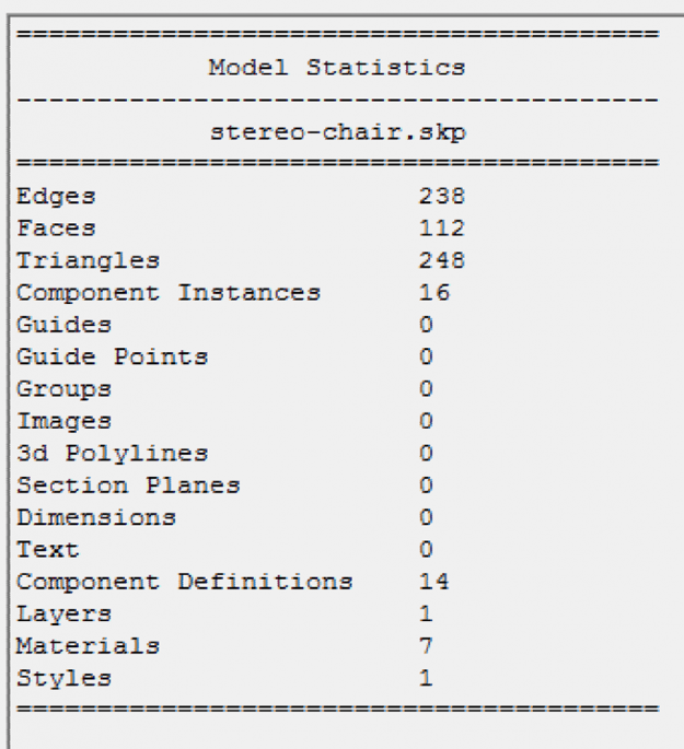
- In the Word document, type ‘CleanUp Model’, copy the screenshot of the model. Then open the next text file and copy the new Model Info into the document. a. Notice the difference in the numbers.
- Manually inspect the model for extra lines and hidden faces and other issues. (Note: this step will take the most time and also has higher points if done thoroughly.)
- Screenshot the model.
- Extensions -> Model Info -> Statistics to File a. Name the file with a different name [file name].txt and choose to save to the Desktop. Click Save.
- In Word, type ‘Manual Clean Up’, copy the screenshot of the model. Then open the newest text file and copy the next Model Info into the document.
- Use the Probes extension to identify Face Normals that are flipped. Extensions -> Probes -> Normals. Keep in mind that this extension will not work on Groups or Components unless you are able to access individual face.
- The three lines produced when hovering over a surface should all be facing out from the direction the surface is facing. If you do not see all three lines (Red, Green, Blue) then your Normal is flipped.
- Take one last screenshot of the model with all corrected Normals.
- In Word, type ‘Normals Flipped’, and copy the screenshot.
- The last step is to use the Position Camera option, Camera -> Position Camera to select a location that will allow you to view the model from a human perspective. If you see the height in the bottom Window that says Eye Height is more than 5’ 6”, you will need to adjust the height by using the Position Camera again.
- Find a good view using the Walk capability with the mouse, Camera -> Walk.
- Add Materials of your choice to the model and turn on Shadows (the default lighting source in SketchUp) View -> Shadows.
- Adjust your view, keep in mind it needs to be from human height, so use the Position Camera option with Walk and Look Around to help you find the best view without changing the height. You can consider a view from inside the model or outside the model, it is up to you.
- Take a screenshot of the final model with materials and lighting.
- In Word, type ‘Final Model’, and copy the screenshot.
Grading Rubric
| Criteria | Full Credit | No Credit | Possible Points |
|---|---|---|---|
| Screenshot of model | 1 pts | 0 pts | 1 pts |
| Screenshot of model statistics | 1 pts | 0 pts | 1 pts |
| Screenshot of model after using clean up | 2 pts | 0 pts | 2 pts |
| Screenshot of model statistics after using clean up | 2 pts | 0 pts | 2 pts |
| Briefly describe the differences, how much optimization has happened | 1 pts | 0 pts | 1 pts |
| Screenshot of the model after manual cleaning | 2 pts | 0 pts | 2 pts |
| Screenshot of the model statistics after manual cleaning (if done thoroughly) | 2 pts | 0 pts | 2 pts |
| Screenshot of face normals flipped | 2 pts | 0 pts | 2 pts |
| Screenshot of Final Model (as described in instructions) | 2 pts | 0 pts | 2 pts |
| Total Points: 15 pts |
Submit your file
Upload your word document and your SketchUp file to Lesson 3 Optimization Assignment.
3.6 Create a Building
3.6 Create a Building
3D Model Assignment
In order to deepen your modeling expertise, we would like you to create your own 3D model of a building. There are a number of options, and while we provide general guidelines, we leave it up to you to choose your route. Modeling is really a rather personal matter and finding your own style is important. We provide more information and some general guidelines below.
Basic Requirements
Now that you are somewhat familiar with SketchUp, your task is to create a model of a building. This model does not need to be an architectural sketch but should be perceptually similar to the original. You should pay attention to things such as windows, roof shape, textures, etc.
These are the basic requirements. If you stick to them and deliver a SketchUp model that meets these criteria, you will receive 90% of the possible points. We have a number of options below that will allow you to receive 100%. Basically, you have to include at least one advanced feature.
Advanced Requirements
Below is a list of things you can do to fulfill advanced requirement criteria. You do not have to choose them all. You can do just one or however many you would like to tackle. Generally speaking, you need to provide a model that shows a higher level of sophistication/complexity, not necessarily for all its features but for some. It is necessary that you provide a brief 1-2 paragraph write-up that explains how you improved the model with added detail. Alternatively (or in addition), there are steps you can perform that would satisfy the advanced requirements. Here is the overview:
- Option 1: Model certain aspects of your building in great detail (e.g., windows, doors) or add other more sophisticated features to your model, such as embedding it in a scene or creating a model that is geo-referenced. Document your efforts in a 1-2 paragraph write-up that explains how you added detail and why you consider this to be beyond the basic requirements.
- Option 2: Create a model of a Penn State campus building. Warning: Most of them are rather complex. Below are a couple of comments on how to use Google Earth / Street View Geolocation in SketchUp to create such a model.
- Option 3: You may have seen our collection of historic Penn State Campus buildings on Sketchfab (Links to an external site.) [54]. The Historic Campus Project evolved out of a collaboration with Penn State's Library. There are a couple of building models missing. We have collected information about the missing buildings. If you are interested, please send me an email and I will share these resources with you and if what you create is of reasonable quality we can integrate your model into our collection.
- Option 4: Create your own Sketchfab account and share your model with us this way. Exporting SketchUp models to Sketchfab is easier in the Sketchfab Pro version, as there is a plug-in for the export created by Alexander C Schreyer. However, you can also export and import the model that you have. It is sometimes a bit tricky as glitches in your model (e.g., messy topology, missing textures) are compensated in SketchUp that start showing up once the model is exported. This document (Links to an external site.) [71] instructs you on how to integrate a Sketchfab model to your website.
Additional Information
As mentioned before, modeling is a rather personal experience, there are many ways to model and in the end, you might find your personal style. Here are three examples of how you can arrive at a building model:
- SketchUp has a feature called Matching a Photo to a Model [72]. What it allows you to do is to use a photo taken of a building and create a 3D model based on this photo with some rather intriguing tools that take into account the perspective found in the photo / identified interactively and adjust it to create a proper/correct 3D model. While this method is intriguing, it does require you to have good photos of buildings and it requires a bit more training to get good results. If the photo is good and you have put in some effort, you will be rewarded with a realistic-looking 3D model.
- You can look for basic or incomplete models in the 3D Warehouse in SketchUp. Please do not submit an existing model from the warehouse or elsewhere as part of your assignment! What is legitimate to do though, is to use an existing model as a basis. One example: If you search for "Old Botany" in the 3D Warehouse, you will find a model of Penn State's Old Botany by a user name 'faith'. This model is not really a model, as it does not have proper geometries (for example, the windows). But, it is possible to use this model as a template and create a proper model around it.
- We frequently use SketchUp's heritage. What this means is that SketchUp was created by Google. There is a feature in SketchUp called "location". It can be added to your interface going through View>>Toolbars>>Location. This feature allows you to select a building that Google has integrated into its Google Earth efforts. The advantage is that your models are instantly geo-referenced. If you combine this feature with other Google products such as Google Earth (which allows for measuring the size and height of a building) and Google Street View, you have a really powerful tool at your fingertips for creating building models of many places on Earth.
Submit your file
Upload your SketchUp file to the Lesson 3 3D Model Assignment.
| Criteria | Full Credit | Half Credit | No Credit | Possible Points |
|---|---|---|---|---|
| The perceptual appeal of the entire model | 6 pts | 3 pts | 0 pts | 6 pts |
| Level of realism of doors | 2 pts | 1 pts | 0 pts | 2 pts |
| Level of realism of windows | 2 pts | 1 pts | 0 pts | 2 pts |
| Detail of the roof and associated features | 2 pts | 1 pts | 0 pts | 2 pts |
| The complexity of the building | 3 pts | 1.5 pts | 0 pts | 3 pts |
| The level of model optimization | 3 pts | 1.5 pts | 0 pts | 3 pts |
| Naturalness of textures | 2 pts | 1 pts | 0 pts | 2 pts |
| Total Points: 20 pts |
3.7 Test Your Knowledge
3.7 Test Your Knowledge
This is an ungraded assignment to test your knowledge.
3.8 SketchUp and Sketchfab
3.8 SketchUp and Sketchfab
Once you have completed your model and would like to proudly share it with the world (non-mandatory), there are again different ways to accomplish that. One of the most prominent platforms for sharing all kinds of 3D models is Sketchfab [73]. The models that you saw earlier in this module, embedded into the course website, are hosted on Sketchfab. Many modelers allow you to use their models in different contexts and Sketchfab is continuously developing ways that will make your models even more accessible such as built-in VR features. We will be using Sketchfab to organize the final submission of this module and to give you an idea of how to share 3D models that you create.
To finalize your modeling assignment, please create a Sketchfab account.
3.9 Resources
3.9 Resources
SketchUp official home page [74]
The official SketchUp YouTube channel [75]
The official SketchUp Community Forum [76]
SketchUp Help Center: Quick Reference Card [63]
In addition to the essential training course we used in this module, there are numerous courses that might be of interest. Simply search for "SketchUp" at Lynda.com [77].
Summary and Tasks Reminder
Summary and Tasks Reminder
You have gone through a hands-on modeling process in this lesson using SketchUp. While there is still a learning curve and every powerful tool requires practice, SketchUp has many, many features that make modeling easier. From its incredible warehouses to its geo-location features, it offers modelers inside and outside the geospatial sciences a lot of options for exploring the third dimension. For many applications, it is important to have a tool like SketchUp as it may be the only option to create a 3D model. It is also a good learning experience to come to appreciate the effort that has gone into designing software such as City Engine, which uses an entirely different approach as we will explore in the next lesson.
Reminder - Complete all of the Lesson 3 tasks!
You have reached the end of Lesson 3! Double-check the to-do list on the Lesson 3 Overview page to make sure you have completed all of the activities listed there before you begin Lesson 4.
Lesson 4: Introduction to Procedural Modeling
Overview
Overview
Lesson 3 has introduced you to hands-on 3D modeling using an efficient approach for various modeling purposes. Instances of when you need hands-on modeling are: (a) you are interested in a substantial amount of detail in your models, (b) your models are non-existent anymore and cannot be, for example, scanned, or (c) you’d like to make use of a substantial asset warehouse that provides you with professionally designed items such as fridges or couches. As you can easily imagine, this approach will be prohibitive if you are interested in modeling entire cities or any large number of buildings, if you would like to test changes quickly (e.g., increzasing the number of floors), or if you need flexible access to your models, for example, through the internet.
In contrast to modeling by hand (also referred to as static modeling), the general concept of procedural modeling has been discussed in Module 2. Rather than modeling individual buildings, procedural computing (as a basis for procedural modeling) is the process of creating models algorithmically instead of manually. This chapter will provide a more detailed introduction to procedural modeling as it is the basis for modeling cities and other geographic scale information in GIS environments. However, we decided not to teach a specific software as a generating platform in this course. We are already introducing you to a number of software options and ESRI CityEngine, although a powerful tool, requires a bit more time than we have in one or two lessons. We will provide you with resources and a demo (in later lessons) that show some of the functionality but do not expect you to learn CE for this course. Yet, we would like you to understand procedural modeling. Later in Module 5, you will explore how procedural rule packages (that we created for you) can be applied in ArcGIS Pro (this is also in line with the long term strategy of ESRI). What this means is that you will be able to modify rules created by a procedural modeling software but you do not have to learn the specifics of the software (City Engine). As Arc GIS Pro is a rather new software product the functionality to change procedural rules is still limited but improving from version to version. The software has already been updated twice since we started designing this course.
Learning Outcomes
By the end of this lesson, you should be able to:
- Define the concept of procedural modeling rules and coding (.cga or computer-generated architecture)
- Contrast procedural rule modeling and hands-on modeling
- Identify advantages and challenges of procedural modeling rules
- Demonstrate the results of procedural modeling rules for the campus
Lesson Roadmap
| To Read |
|
|---|---|
| To Do |
|
Questions?
If you have any questions, please post them to our "General and Technical Questions" discussion (not e-mail). I will check that discussion forum daily to respond. While you are there, feel free to post your own responses if you, too, are able to help out a classmate.
4.1 The Concept of Procedural Modeling
4.1 The Concept of Procedural Modeling
As discussed in Module 2, procedural modeling is about constructing detailed textured 3D models by formulating rules instead of manually modeling them (CityEngine [79]). These rules are constructed based on a specific type of shape grammar (Stiny & Gips 1971). Stiny and Gips invented shape grammars and defined shape grammars as a method of two and three-dimensional shape generation. A shape grammar is a set of shape transformation rules to generate a language or set of design (Knight, 1989; Duarte & Beirao, 2010). They are spatial rather than symbolic and also non-deterministic. It means that the designer is not constrained by a limited choice of rules (Knight, 1989).
Shape Grammar is a way of defining algorithms. It makes design, generally speaking, more understandable. In order to read and use shape grammars, we need to have a short review of the basic terms below (Stingy, 1980):
- Grammar: A set of rules of transformation.
- Language: A set of all the possible designs can be generated with the grammar rules.
- Shapes: points, lines, planes, or volumes.
- Labels: symbols, numbers or words that restrict the rules that apply.
- Initial Shape: The first labeled shape that the rules are applied to.
- Rule: A process transfer shapes and label from the left side to the right side (α-->β).
- Transformation: Usually is Euclidean transformations, changing location, orientation, reflection, or scale of a shape.
- Derivation: apply the rules to the initial shape recursively and generate new shapes.
A shape rule specifies how the existing part of a shape can be transformed. It consists of two labeled shapes on each side of the arrow (α-->β). Each labeled shape is made up of a finite set of shapes which are points, lines, planes, or volumes. For instance, in the figure below a simple shape grammar consisting of two rules is defined. The first rule specifies that a triangle with a dot can be modified by adding an inscribed triangle and removing the dot from the original triangle. The second rule states that one can also simply remove the dot from a triangle with a dot. Given the initial shape of a triangle with a dot, a shape can be derived by applying these two shape rules in a different order, namely, rule a -> rule a -> rule b in this case.

To create an urban plan or design, the complexity and characteristics of that environment can be interpreted as shape grammars to increase flexibility in suggesting the number of solutions and scenarios. Duarte & Beirao (2010) indicate that old urban plans are not compatible with contemporary urban societies and that there is a need for flexible designs. They propose that there are two ways to use shape grammars in urban environments: (1) as an analytical tool to find the structure of an existing design, or (2) as a synthetic tool to create a new language for design. Both methods automate the process of design generation.
Although a shape grammar can be generated by hand, for more complex rules and choices, a generation engine is needed to create and display geometries and decide which shape rule to apply. ESRI CityEngine is a generation engine for creating shape grammars, applying rules, and generating shapes. CityEngine’s programming language to define shape rules is called CGA (computer-generated architecture) shape grammar. The next section briefly explains the CGA shape grammar and how it can be applied to create virtual 3D models of cities.
Creating a model based on rules is less labor-intensive. However, the preparation of rules is time-consuming. The strength of this modeling approach is that once the rules are created, generating and creating models takes a small amount of time. The following diagram shows the total cost of procedural modeling vs handcrafted modeling.
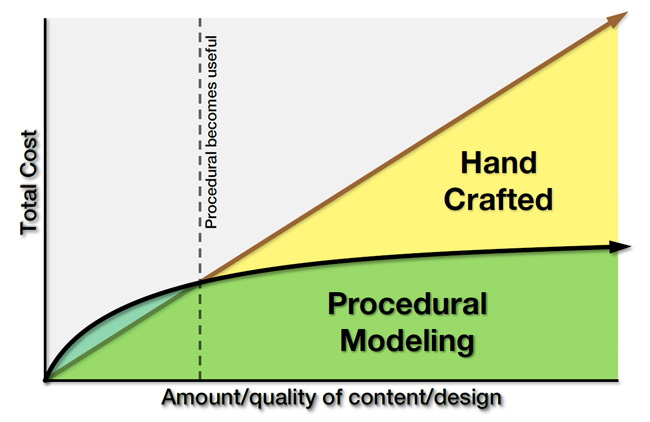
Required Reading Assignment
To give you a deeper understanding of Shape Grammars, we would like you to read Shape Grammars in Education and Practice: History and Prospects [78] by Terry Knight. Knight, T. W. (1989).
4.2 Introduction to CityEngine and its CGA Shape Grammar
4.2 Introduction to CityEngine and its CGA Shape Grammar
Introduction
In this section, we focus on an introduction to ESRI CityEngine as an instance of procedural (grammar-based) modeling software. Although this software won’t be used in this course, the result of its procedural modeling will be applied in lessons 5 to 7 that will introduce you to ArcGIS Pro. CityEngine is standalone desktop software. ‘The computer is given a code-based ‘procedure’ which represents a series of commands - in this context geometric modeling commands - which then will be executed. Instead of the "classical" intervention of the user, who manually interacts with the model and models 3d geometries, the task is described "abstractly", in a rule file’ (CityEngine [79]). The set of generic procedural rules can be used or modified when creating virtual cities. Moreover, new procedural rules can be defined, modified, or rewritten to create more detailed and specific designs.
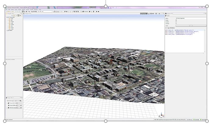
Please watch the video below to learn more about the user interface and navigation in CityEngine.
Video: CityEngine Essential Skills: Exploring the User Interface and Navigation Controls (15:47)
This tutorial will give you a quick overview of CityEngine's navigation tools and user interface. And for this project, we'll use the International City we created in the previous tutorial. If you're just joining the series, you can create this project through the City Wizard. To access the City Wizard, go to the File menu and click New. This will open a new dialog box and you can choose City Wizard in the CityEngine folder and then click Next. Give a name to your city. I'm gonna call this one International City. And for our purposes, we can just accept the defaults and scroll through the wizard. Once you're done, click finish. And for me, I've already created this city, so I'll click cancel. Now your city might take a little while to generate but pretty soon you'll have something that looks similar to what you can see here.
Now for this lesson, let's set up a scenario. So just imagine that you're an urban designer and you've been charged with creating a new residential development. To help you complete this task we'll build your understanding of the user interface and develop your skills using the navigation tools in CityEngine.
First, let's look at the main windows in CityEngine. The first is the scene editor. In our scene, we have the environment layers that control the scene's light and the scene's panorama. One of the functions of the scene light layer is that I can come in here and change the solar intensity values. I can decrease intensity to maybe 0.5 and we can see the light change in the scene. I'm going to set it back to 1 just to make the scene a little brighter.
Next, we have map layers and these contain images that make up the base map and the context for your scene. We also have something called the obstacle map layer and this constrains where the city will be generated. So if I go ahead and turn off the heightmap layer, and turn on the obstacle layer, you can see those areas in black represent areas of vegetation and water in the landscape. And CityEngine recognizes that it can't go ahead and build buildings in these areas. So this is a useful way for you to help constrain where your city will actually be generated.
Finally, we have graph layers. What we can see here is a street layer and it's made up of networks. And these are like our edges and nodes and blocks, and these are used for generating shapes and models dynamically using CGA rules.
Next, let's look at the Navigator window. The Navigator is used for project and scene management and consists of the folders you can see here. The first is the assets folder. The assets can be in different formats. For example, obj, and these are used by CGA rules to texture the models you see in the scene. Next is a data folder. I use this folder to store GIS data in a file geodatabase format. You can store things like colada files or other additional datasets here too. The images folder stores additional imagery like viewport snapshots, for example. The maps folder contains the images used by the map layers. So for example, we have the texture image that's creating the base map for this scene. And we also store the obstacle image here that we saw earlier. The models folder is where you can store 3D models exported from the CityEngine scene. The rules folder contains the CGA shape grammar rule files. And these rule files call on the assets that we saw earlier to create the textures for the 3D models. And next is the scenes folder. So the scenes folder is where we store all the scenes that we build in CityEngine. And finally, we have the scripts folder where you can store things like Python scripts.
If you ever need to add any additional data to any of these folders you can easily do that by dragging and dropping from your native file browser. You have the option here to configure the drag-and-drop setting, so I can link to files so if they're updated on my folder system they'll update directly in my navigator or my workspace as well. Or I can choose to copy the datasets into the workspace. Besides project management, this window lets us open a scene by right-clicking and we can also access the CGA rule editor window by double-clicking on one of the CGA rules in the rules folder. Once the CGA rule editor is open, we have the option to view and edit the rules either in a text view, which we can see here, or a visual view. And we'll cover CGA rule editing in more detail later. And I'll just switch it back to the textual view.
Now let's take a look at the inspector window. The inspector shows all the attributes and the parameters of the assigned CGA rules. To view rule parameters, first select some buildings by holding the left mouse button down and dragging from left to right. You see a blue rectangle on the screen and when you release it, you can see some buildings highlighted in blue. And then in the inspector window on the right, you can see under the street parameters, the different values available to change. So we have things like street width and sidewalk width and I can update these based on my design intent or maybe feedback from a client. And finally, we have the log window. And this window is useful for troubleshooting errors or if you're getting any strange behaviors. And it gives you good feedback ranging from informational messages to severe errors like out of memory for example.
Okay, now we have an overview of some of the windows in the user interface. Let's take a look at one of the main windows, which is a 3D viewport. And this is where we visualize and interact with the 3d scene and it's where I'll sketch out the new development. First, let's choose an area suited for new development. From looking at the scene, I think somewhere down by the waterfront would be good. To zoom to this area, hold the left mouse button down and drag from left to right to select some of the streets. Then click on the frame selection tool from the toolbar in the top right of the viewport. This quickly zooms me into the area. Another way to quickly navigate to this area is to create a bookmark. The bookmark menu is located in the top right of the viewport window and it has a small star icon. Click on this and then from the drop-down menu choose to create a new bookmark. I'll call this one project area and click OK.
So now that I've saved the extent of my project area, I can quickly zoom out. So if I press the A key, it will zoom me out to the extent of my whole project. And to zoom back again, I'll go up to the bookmark menu and choose project area. Depending on what you're doing in your project, you might like to have another viewport window open to give you a more complete view of your project or of your scene. So for my purpose. I think I would like to have the perspective scene as well as a plan view or a top-down view. To do this, I can open a new viewport window from under the window menu, and I can click and drag the viewport and drop it below my original viewport window. If I click on the camera views, you can see that this is in a top-down view. Now I chose this view for my specific purpose, but there are also a number of default views that you can use and they're designed for other tasks. So the first one is called the default view, handily enough, and this one is really good for an overview of your scene and for management tasks like import and export. The next one we'll take a look at is called the minimal layout. Now this one has a perspective view and some editors open, which makes it pretty good for presentations. The next two views are similar to the default views, but we get two views. So we have a perspective at the top here and a plan view at the bottom. And you can also have this in a vertical layout. And then finally to make rule editing more efficient, we have a couple of views here. Let's take a look at the standard rule editing view. This layout has one perspective view and leaves more area for the CGA editor, so it's especially suited for editing rules.
Okay, now I'm just going to return to the default layout because that's going to suit my purpose of sketching out the new development. Now before we get started with some of the navigation in the scene, I want to show you some of the view settings that you can adjust, so you can see the models better. So under the view settings menu, here I'm going to uncheck Wireframe on Shaded Textures. And now we can get a better view of what our models are going to look like. Now let's save this perspective view. So under the window menu, choose Layout and then Save Perspective As. Then all you have to do is give this a name. For me, I'll call this project view and choose okay. So now I have this perspective saved if I ever want to use it in a future project. Now I have a viewport layer, let's look at how to navigate. So I can use the navigation tools, tumble, track, or dolly. Or it's even easier to use the shortcut keys. So here we have alt and the left mouse button and to pan, alt and the middle mouse button and then to zoom in and out, I'm using the alt key and the right mouse button. A recommended navigation workflow is to select the features or the area that you want to work in and choose a frame selection tool. Once you're zoomed in closer, you can explore the selection using the tumble, track, and dolly shortcut keys. Also, if you ever want to deselect a selected feature, you can just hold down the ctrl, shift and A keys.
Now let's look at how we can interact with the models in the viewport using selections. Selecting features is also an essential skill for applying rules. So one way we can select features is using a rectangle. So here from left to right if I drag, I select all the features that fall inside the rectangle. But if I go from right to left, I get all the features that touch the borders of the rectangle, as well as fall inside. Another thing I can use is from the selection menu. So I can choose to subtract from the selected features, and we see the result there. I can also do things like invert the selected features, and we can see the results in the window here. And then to deselect the selection, you can do control, shift and A.
Now let's see how we can use selections to apply rules for their new development. In this step, we'll use some of the object edit & transform tools to create the new development. First I'll zoom back to the study area using the bookmark. And the tools that we're looking for are located here above the viewport. I'll select the polygon street creation tool and quickly sketch out some streets and blocks for the new development. I'm going to select some of these blocks, so I'll do the drag a rectangle selection technique. And if I right-click, I can choose select, and from the context menu, I'm going to choose select objects of the same group. Then under our block parameters in the inspector window, I'm going to change the type to recursive subdivision, and adjust some of the lot areas. Once I'm happy with the design, I'll go back in and select the blocks again, and right-click and choose select objects of the same group. And then I'm going to drag and drop this international city rule directly on to my selected features. And straightaway you can see we've generated a new urban development. So in the inspector window, you can see under the International City group we have some parameters available to change. So under type, we have different building types, high-rise, office, residential. I'm going to leave this as apartment.
And sometimes when you're working with a complex scene like this one, if you want to make an edit, it's useful to be able to select the building you want to interact with and then isolate it. So to do that, select a building with your selection tool and then press I on the keyboard to isolate the selection. And then you're able to come in and edit the specific building you're interested in. So here I'm changing the tree type to a random forest mix, and I'm changing the building type to an office building. So once you're happy with your edits, you can press I, and your models will come back. Now if we press the A key, we can zoom out to see the entire scene. I'll zoom in a little bit here. When you're finished with the visualization and you want to see perhaps more of your model, you can press the spacebar and this will maximize your screen real estate by hiding some of the other windows. Now we'll change some of the display settings so we can see the models a little bit better. So here I'm going to add some shadows. I think I'll also add the ambient occlusion as well. And then we'll turn off the grid that you can see there so we can better see the models. These kinds of view settings are really good if you want to take some high-quality screenshots of your CityEngine scene.
Okay, so now you know your way around CityEngine. You'll use your navigation skills and project management knowledge in the next tutorial, which shows you how to create your first CityEngine project.
Transforming 2D Data to 3D Assets
Transforming 2D Data to 3D Assets
CityEngine is suitable for transforming 2D GIS data to 3D cities. GIS data such as points, lines and polygons can be used to create 3D models. The current version of CityEngine connects to ArcGIS through data exchange. However, it is not tightly integrated into the ArcGIS system yet. The created 3D models can be exported to other software for analysis or editing such as ArcGIS, Maya, 3ds Max, Google Earth, the Web (see Lesson 7) or Unity (as we’ll explore in Lessons 8 and 9) (CityEngine Frequently Asked Questions [80]). The following figure shows different data formats of input and output to and from CityEngine. CityEngine does not support automatic creation of 3D city models. The platforms that support automatic creation of 3D models in urban environments, use oblique imagery or LiDAR data to reconstruct volumes and building shapes based on point clouds and aerial imagery. However, the main strength of CityEngine is data creation, the use of other datasets such as geodatabases and export capabilities. A single procedural rule can be used to generate many 3D models. GIS data feature attributes can be used to add more accuracy to the model. Instances of such attributes are building height, number of floors, roof type, and roof materials.
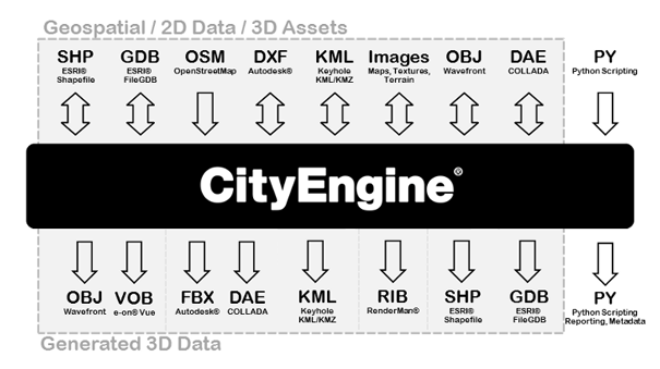
Understanding CGA Shape Grammar
Understanding CGA Shape Grammar
As mentioned, CityEngine uses a programming language called CGA shape grammar. Rules written with CGA are grouped into rule files that can be assigned to initial shapes in CityEngine. For instance, 2D building footprint polygons can be assigned a rule file containing the rules for interactively creating building models from the 2D polygons as illustrated in the figure below. One of the rules defined in the rule file needs to be declared as the starting rule, meaning that the generation of the building model will start with that rule.

The initial shapes to start the iterative refinement process can be created either in CE or imported from another source. More precisely, there are three ways of creating shapes in CityEngine (see image below): (1) manually creating shapes, (2) deriving shapes from a graph (e.g., street segments and lots from road network), (3) importing shapes (e.g., 2D building footprints from a shapefile).
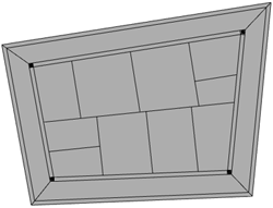
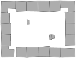
All CGA rules have the format Predecessor --> Successor
Where “Predecessor” always is the symbolic name of the shape that should be replaced by the “Successor” part on the right side of the arrow. The “Successor” part consists of a number of shape operations that determine how the new shape is derived from the input shape and symbolic names for the output shape(s) of the rule (which can then be further refined by providing rules where these shape symbols appear on the left side of the arrow). To give an example, the following two rules create a block separated into 4 floors from a 2D polygon:
Lot  --> extrude(10) Envelope

Envelope --> split(y) { ~2.5: Floor }*
The first rule states that the initial 2D shape (“Lot”) should be replaced by 3D shapes called “Envelope” that are produced by extruding the initial 2D polygon by 10 units. The second rule says that each “Envelope” shape created by the first rule should be split along the vertical y-axis into “Floor” shapes of height 2.5, so four floors altogether. We could extend this simple example by adding rules for splitting each floor into the front, back, and side facades, applying different textures to these, inserting windows and doors, and so on. Application of a rule file to the initial shapes results in a shape tree of shapes created in the process. The leaves of the tree are the shapes that will actually make up the final model, while all inner nodes are intermediate shapes that have been replaced by applying one of the rules. The shape tree for the simple example would start with the “Lot” that is replaced by an “Envelope” shape, which in turn is replaced by the four “Floor” shapes making up the leaves (see figure below).
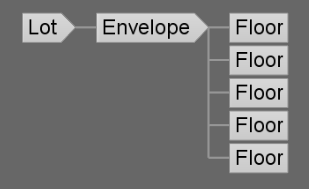
CGA defines a large number of shape operations (see CGA Shape Grammar Reference [82]). Shape operations can have parameters such as the extrude and split operations in the previous example. Rules can also be parameterized to provide additional flexibility (see Parameterized Rule [83]). Moreover, rules can be conditional (see Conditional Rule [84] or Stochastic Rule [85]), and rule files can contain attribute declarations (see [86]Attributes [87]), function definitions (see Functions [88]), and style definitions (see Styles [89]). If you want to learn more about writing CGA rules, tutorials 6 to 9 at Introduction to the CityEngine Tutorials [90] would be a good starting point.
Using CGA Rules
Using CGA Rules
To create building geometries through CGA rules, the following general workflow can be used:
- In CityEngine, the “Lots” serving as initial shapes for constructing buildings. Lots are either created in CityEngine (drawn or created based on a graph) or imported.
- To create 3D models, the user selects which Rule File (.cga) and Start Rule to apply to these initial shapes. The user can either assign one rule to all building lots or assign rule sets on a selection of buildings.
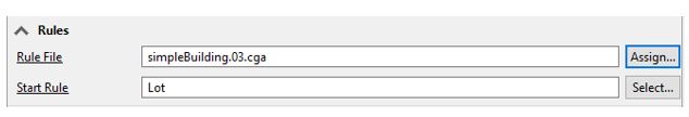 Credit: CityEngine Help [81]
 - Then, the user can trigger the application of the rules to the selected shapes. Therefore, it is important that the Start Rule of the shape is present in the rule file. Otherwise, no rule can be invoked. Extrusion is the first step in generating a 3D mass from a 2D footprint. The operations provided in CGA such as “extrude” can be adapted to create a complex architectural design. A simple CGA rule for building extrusion can be written as follows:
Lot --> extrude (4) Building

Or:

attr height = 30

Lot -->extrude(height) Building
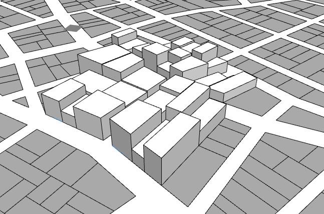 Credit: CityEngine Help [81]
 -
In order to modify the resulting 3D models, different possibilities exist: (1) edit the rules by scripting, (2) overwrite the rule parameters of a rule set on a per-building basis, and (3) if stochastic rules are used (rules with random parameters), the random seed of all or single buildings can be altered. The last method is used in creating virtual cities that should have certain characteristics. These types of randomization are not a representation of reality.
The following figure shows how a rule can be overwritten (2nd method mentioned above). This window provides values to the parameters of a rule. To overwrite the rule, there are some options: (a) to use the rule-defined value, (b) manually add a user-defined value, (c) object attribute, (d) shape attribute, or (e) layer attribute. Layer attribute is to choose attributes based on shapefiles or geodatabases attribute table. For instance, if you have height value as a field in the building footprints’ attribute table, you can use it to automatically generate extrusions. Other instances of fields that can be used for buildings are roof types, roof materials, façade materials, etc.
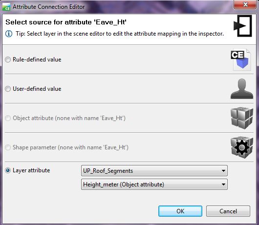 Credit: ChoroPhronesis Lab [28]
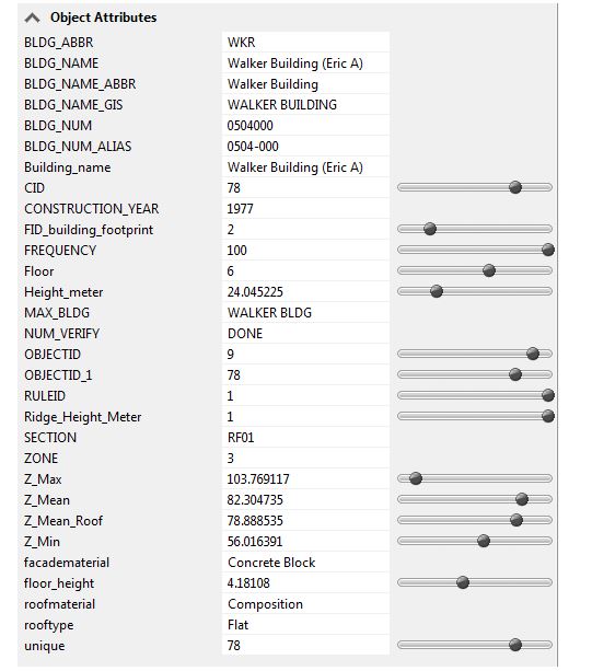 Credit: ChoroPhronesis Lab [28]
 - After the design is finalized, the user can export any selected shapes including buildings or streets to other platforms or publish the results online. (CityEngine [81])
4.3 Introduction to Procedural Modeling for UP Campus
4.3 Introduction to Procedural Modeling for UP Campus
Introduction
Airborne LiDAR data provides information on variable elevations. This elevation information is useful in both creating the DEM (digital elevation model) and estimating buildings’ height. The airborne LiDAR data collected for Penn State campus is in 25 cm intervals. You can see the Campus LiDAR point clouds of buildings and vegetation in the Figure below. All noises and irrelevant categories are removed for presentation purpose.
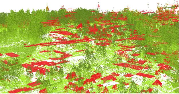
LiDAR returns information for two types of elevation models: (1) DSM or digital surface model (Figure below) which is a first return surface including anything above the ground such as buildings and canopy. (2) Topography: the ground or bare earth which is referred to as DEM (digital elevation model).
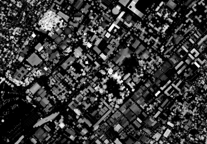
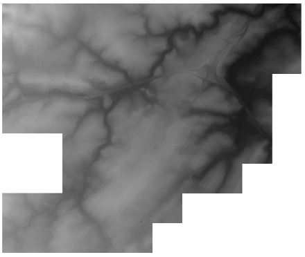
Building Footprints
Building Footprints
In CityEngine, for creating a 3D model of Penn State campus, the first step is to insert a DEM. Having a DEM defines the coordinate system and the ground elevation base for locating building footprints and streets. To estimate campus building heights, a digital surface model is created. Based on the normalized DSM layer, the minimum and maximum heights of every point are extracted. Extracting the roof shape and finding the mean of elevation of points within each roof section, the mean of elevation for every part of buildings is calculated (Figure below). All this preparation is done in ArcGIS Desktop to prepare the base shapefile to be imported to CityEngine.
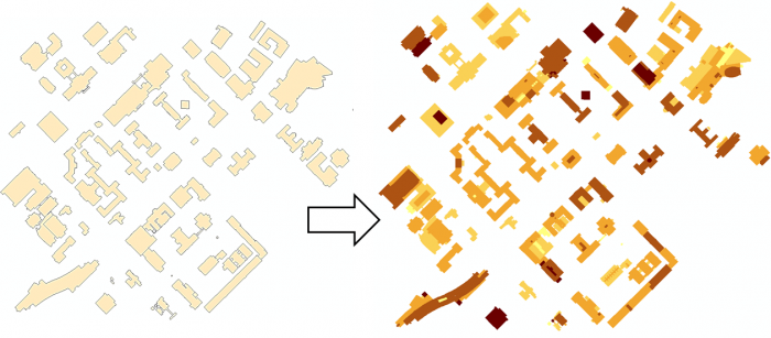
Every single object of the building footprints imported to CityEngine will be considered as one shape or Lot. By clicking on any part of the building footprints, a shape will be selected and you can see the shape number in the inspector menu in the following figure. Each shape has many attributes for each section of buildings such as the mean of height and roof types.
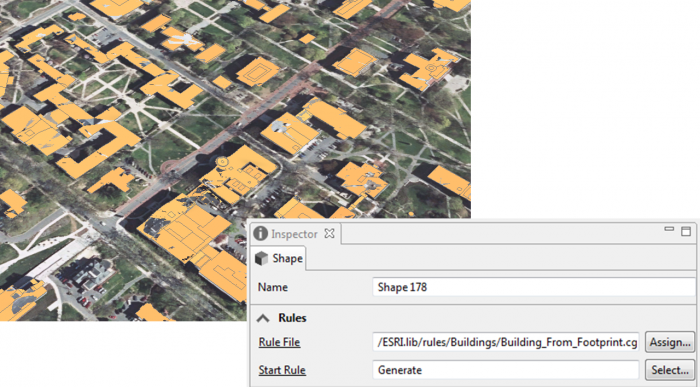
The figure below shows the extrusion rule assigned to the shapes based on the height values in the attribute table.
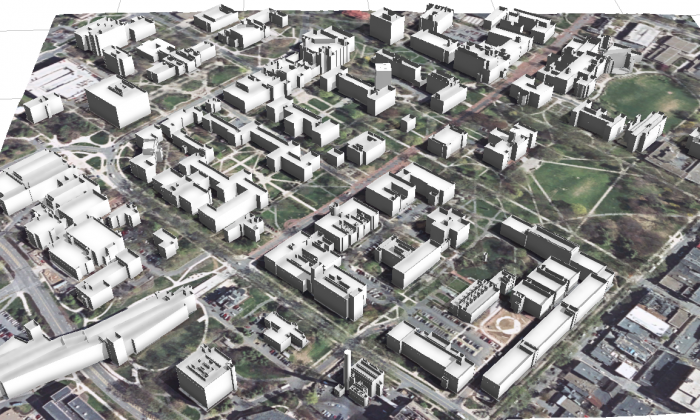
In the following figure, you can see rule parameters in the building settings that can be overwritten base on layer attributes.
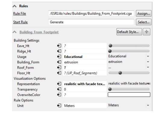
Roof Shapes
Roof Shapes
In the CityEngine CGA grammar rules, basic roof shapes such as flat, hip, gable, pyramid, and shed are defined. Examples of basic rules for different roof shapes are as shown in the figure below:
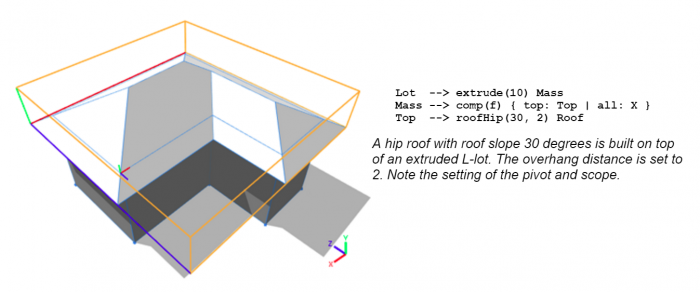
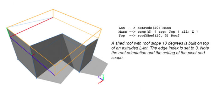
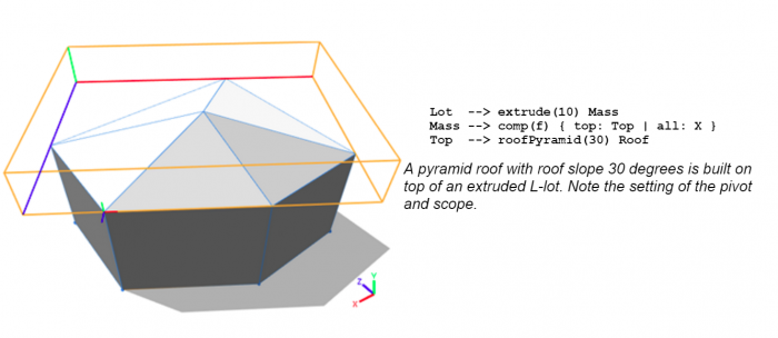
However, roof structures of campus buildings are complex. For more realistic and sophisticated roof types, new specific rules should be written for each complex building and this inverts the aim of procedural modeling which is facilitating the modeling process instead of hand modeling each building. Instead of writing complex rules or assigning one roof type for each building footprint, a combination of roof types is used for each building. In other words, each section of a building with a different height value has a roof type assigned to it. This has been possible by the use of LiDAR information. Each building is divided into different roof sections based on different heights and types. For instance, the following figure has a complex roof type. The middle parts are flat with various heights. The edges are shed and need a different rule to be applied.
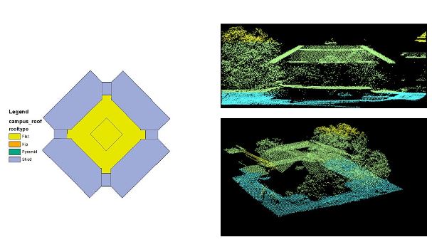
A ‘roof type’ attribute has been created for the building footprints shapefile based on Google Earth images. To select different shapes with similar roof types in CityEngine, a simple python scripting is written. The python editor is executed inside CityEngine and is convenient for writing scripts and executing. The figure below is the window for creating a python module and the next figure shows a sample python code for selecting roof types of the same value.
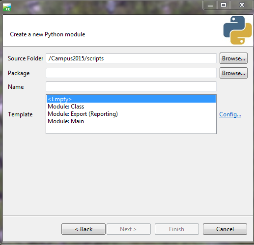
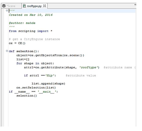
The script then can be run by pressing F9 or selecting Run Script from the Python menu. Then for selected shapes, the rule parameter of roof type is modified. You can see selected shapes and roof type options in the figure below.
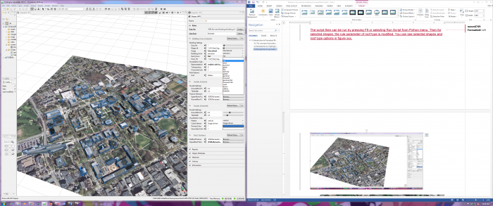
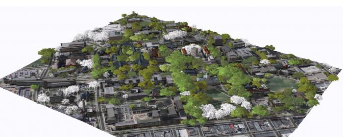
Facade, Trees, Plants
Facade, Trees, Plants
CityEngine rule file of ‘Building_From_Footprint.cga’ has three options for generating façade textures: (1) realistic, (2) Schematic, and (3) solid color. In the Figure below, you can see the three options for façade representation. You are going to explore these options in ArcGIS Pro. ESRI has a library of façade textures for different building types which we have used to texturize campus model. However, for a more realistic view of campus, images from building facades can be captured and used in this model.
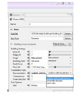
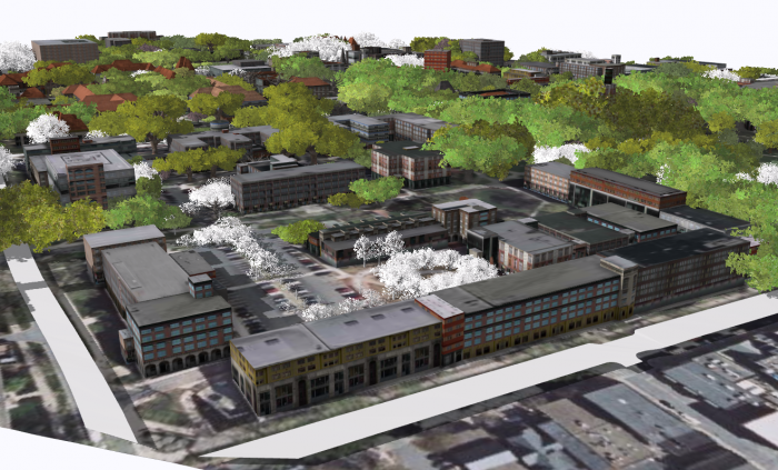
In the images above, you can see that trees have been generated for the campus model. These trees are based on a tree dataset in GIS which has been linked to tree models using “3D Vegetation with LumenRT Models”.This rule [91]covers a lot of common trees found in North America. the models can be previewed in this Link [92].
The first step in creating tree models is to Match LumenRT model names with your tree names. This rule file uses the common name of tree species as the identifier of each model. Therefore, it is very important to keep your tree name in accordance with the name in the rule file. You can achieve this by adding a field in ArcGIS and filled it with the corresponding LumenRT names using Python or create an excel file where you match LumenRT tree name with your own dataset, and then link this file with your original dataset in ArcGIS. The second step is to import the tree dataset to CityEngine and align shapes to the terrain.
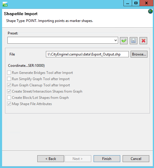
Selecting the tree shapes, you can assign the rule file and generate the rule.
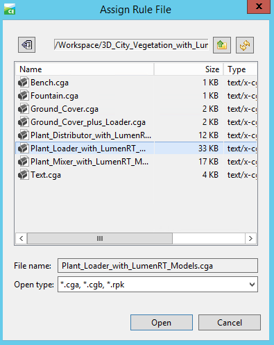
After generating the rule, you may find that the tree models generated are not right. In this step, you need to assign the attributes from the dataset to rule parameters. To do this, simply click on the Attribute Connection Editor near the Name, select layer attribute, and find the field you add to your tree dataset.
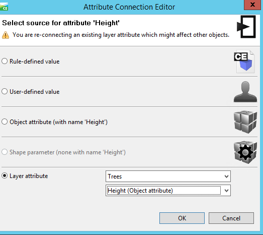
To use the created models, you have two options: (1) export it to other formats, and (2) share it. The model can be exported to different formats such as Autodesk FBX, Collada, KML, and OBJ. For sharing the model, one option is to share the whole scene in the CityEngine Web Viewer. Another option is to share the rules as a rule package that can be used locally on your machine. Having the rule package (RPK), you can share it with others using ArcGIS Pro or ArcGIS Online. In Lesson 5, you will learn how to apply a rule package exported from CityEngine as a symbol layer to your database.
Tasks and Deliverables
Tasks and Deliverables
Models
This assignment has three tasks associated with it. The first task will prepare you to complete the other two successfully.
Task 1: Compare all three models of Penn State’s University Park Campus
Explore all three models and software websites provided below. Working through the questions will help you prepare for Tasks 2 and 3. By now these models should be familiar to you, but you may want to take some notes to help you organize your thoughts and keep everything straight.
- What are the pros and cons of reality modeling in comparison to procedural modeling and hands-on modeling?
- What are the layers that have been modeled in the procedural model (Model 1)?
- Click on one of the buildings or trees in Model 1. What happens? What types of information you can get from each shape?
- Can you find the name of some tree species in the procedural model (Model 1)?
- What is the difference between shell modeling and procedural modeling from GIS Data?
- What types of information can be incorporated into the photorealistic model?
- What are the differences between hands-on models and procedural models in terms of levels of detail?
Model 1 [93]
Procedural model created at ChoroPhronesis [28] Lab using ESRI CityEngine [94] and CGA Shape Grammar rules. This model is shared with you using CE WebScene. You can turn layers on and off, zoom, rotate and explore the part of campus modeled.
Video: Procedural_2015_Jade1 (00:00)
Note: This interface may take a while to load. Please be patient. To see the full size interface with additional options click the Model 1 link [93].
Model 2 [95]
Reality modeling created at Icon Lab using ContextCapture [96] software from Bentley. This model is photorealistic and shared with you as a YouTube video.
Video: Penn State Virtual Campus Project (12:30) This video is not narrated.
If you want to see a larger version of the video, click the Model 2 link [95].
Model 3 [97]
Historical campus models (1922) created at ChoroPhronesis [28] Lab using Sketchup. These models are combined in ESRI CityEngine [94] with trees and base map generated using procedural rules. This model is shared with you as a flythrough YouTube video.
Video: Penn State campus in 1922 flythrough (non-360-degree version) (2:01) This video is not narrated.
If you want to see a larger version of the video, click the Model 3 link [97]. [98]
Task 2: Start a discussion
After reviewing all three models and taking notes, start a discussion on what you believe the advantages and disadvantages are for each of the three approaches. Make sure that you comment on each other's posts to help each other better understand the nuances and details of each one. Remember that participation is part of your final grade, so commenting on multiple peers posts is highly recommended. Please also make sure to use information from the reading assignment on Shape Grammars.
Post your response to the Lesson 4 Discussion (models) discussion.
Task 3: Write a one-page paper
Once you have posted your response and read through your peers' comments, synthesize your thoughts with the comments and write a one-page paper max about the three different approaches.
Submitting your Deliverable
Once you are happy with your paper, upload it to the Lesson 4 Assignment: Reflection Paper.
Grading Rubric
| Criteria | Full Credit | Half Credit | No Credit | Possible Points |
|---|---|---|---|---|
| Clearly names and describes advantages and disadvantages, including time, learning curve, accessibility, applicability, flexibility, etc. | 10 pts | 5 pts | 0 pts | 10 pts |
| Names areas of application that are best suited to each of the approaches | 3 pts | 1.5 pts | 0 pts | 3 pts |
| The document is grammatically correct, typo-free, and cited where necessary | 2 pts | 1 pts | 0 pts | 2 pts |
| Total Points: 15 |
Summary and Tasks Reminder
Summary and Tasks Reminder
We would like to acknowledge that we have by now given you a quite intense tour through various modeling approaches. It is, however, important to have at least an overview of what is currently available as the project you may be working on in the future (past this course) may require you to design a custom made solution. In addition to various workflows including structure from motion mapping and hand-on modeling that we explored previously, this lesson focused more deeply on procedural modeling and its origins in theories of shape grammar. Procedural modeling is a wonderful tool to both explore the organization of built environments in theory but also, more recently, as a powerful tool to make modeling more efficient. ESRI has realized this potential and bought City Engine which was founded at the ETH Zurich (their technical university). Keeping the different approaches in mind it important as we move on in the course.
Reminder - Complete all of the Lesson 4 tasks!
You have reached the end of Lesson 4! Double-check the to-do list on the Lesson 4 Overview page to make sure you have completed all of the activities listed there before you begin Lesson 5.
References
Duarte, J.P.; Beirão, J.N. Towards a methodology for flexible urban design: designing with urban patterns and shape grammars, in Environment and Planning B: planning and design. Vol. 38 (5) 2012, pp. 879-902.
Knight, T. W. (1989). Shape Grammars in Education and Practice: History and Prospects, Internet Paper: http://www.mit.edu/~tknight/IJDC [99].
Stiny, G., & Gips, J. (1971, August). Shape Grammars and the Generative Specification of Painting and Sculpture. In IFIP Congress (2) (Vol. 2, No. 3).
Stiny, G. (1980). Introduction to shape and shape grammars. Environment and Planning B, 7(3), 343-351.
Lesson 5: Introduction to Arc GIS Pro and 3D Modeling ArcGIS Pro
Overview
Overview
In this module, you will build a 2D map of the University Park campus including buildings, trees, roads, walkways, and a digital elevation model (DEM). You will learn how to convert 2D maps to 3D presentations. Then procedural symbology that we have created for you in CityEngine will be imported and applied to the 3D map to create a realistic scene.
Learning Outcomes
By the end of this lesson, you should be able to:
- Explain options for 3D modeling within Arc GIS Pro
- Understand ArcGIS Pro's integrated 2D–3D environment (Local and Global Scenes)
- Convert a 2D map to a 3D scene
- Explain 3D symbology
- Extrude features to 3D symbology
- Find an example of a 3D CityEngine/ArcGIS Pro model: campus model
- Compare procedural modeling rules (.cga) vs procedural rule package (*.rpk)
- Create a 3D model of elevation (DEM)
- Create a 3D scene from a 2D building footprints of campus-based on the DEM
- Employ a procedural rule symbology based on the rule package
- Link procedural rule symbology to attributes table
- Distinguish static modeling from procedural modeling
- Restructure the map and represent the 3D scene based on the imported model
Lesson Roadmap
| To Read |
|
|---|---|
| To Do |
|
Questions?
If you have any questions, please post them to our "General and Technical Questions" discussion (not e-mail). I will check that discussion forum daily to respond. While you are there, feel free to post your own responses if you, too, are able to help out a classmate.
Section One: Create a Map of University Park Campus
Section One: Create a Map of University Park Campus
Introduction
The first step into 3D modeling using ArcGIS Pro is making a map. First, you will create a project. Then you will add necessary data to your map where you have all the tools you need. Then, you will explore the University Park Campus with navigation tools and bookmarks. This 3D model of the University Park Campus will be the final result of this lesson.
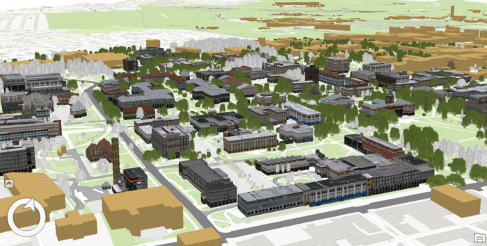
1.1 Start a Project
1.1 Start a Project
If you do not have ArcGIS pro installed on your computer, please install it before continuing.
The first step in making a map is creating a project, which contains maps, databases, and directories.
- Start ArcGIS Pro 2.7
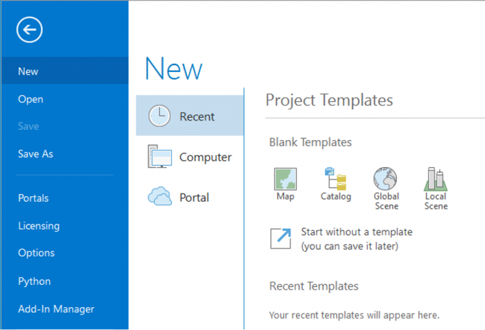 Credit: 2021, ArcGIS [100]
 - Sign in using your licensed ArcGIS account. See this link [101] for how to sign in using the Penn State account.
- When ArcGIS Pro opens, you can see a list of project templates under the heading “Create a New Project”. If you have created projects before, you can also see a list of your recent projects.
Project templates are useful in creating a new project because they have aspects of ArcGIS Pro that are important including folder connections, access to databases and servers, and predefined maps.
A Blank template starts a new empty project. It means you won’t have the aspects mentioned above and will start from scratch to build your project. Scene views are for 3D map presentations. Global Scene is a useful template when your data is best represented on a globe. A Global Scene creates a project based on ArcGlobe (part of 3D Analyst extinction of ArcGIS for Desktop). Local Scene is useful for a small area to perform analysis or edit. It is similar to ArcScene in ArcGIS for Desktop. The Map template is suitable for creating a 2D map for your project. It creates a geodatabase in the project folder.[1]
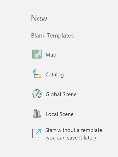
- Click on Map under ‘New’. The Map template is suitable for creating a 2D map for your project. Other templates are for 3D maps. Selecting Map.aptx will let a new window appear: Create a New Project.
- Name the project “UniversityParkCampus”. By default, the project will be saved to the C: Drive where the ArcGIS folder is located. Change the location if desired.
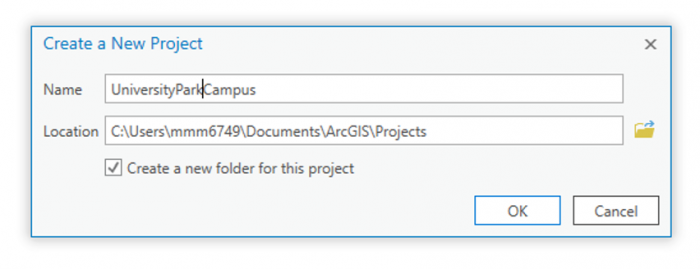 Credit: 2021, ArcGIS [100]
 - Click OK. The project opens and displays a map view.
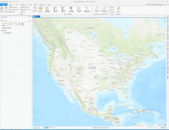 Credit: 2021, ArcGIS [100]
[1] For more information on project templates: (1) ArcGIS Pro [102], (2) GISP, Tripp Corbin. 2015. Learning ArcGIS Pro. Community Experience Distilled. Packt Publishing: P. Accessed September 22, 2016. http://lib.myilibrary.com?id=878863 [103].
1.2 Add Data to the Map
1.2 Add Data to the Map
To explore Penn State’s University Park Campus, you need data. Download the data [104]. You can save the data package on any location on your computer. Please make sure to unzip the file. It is highly recommended that you save data in the project folder you created before, UniversityParkCampus. The reason is that if you have to move to a different computer, saving everything in your project folder will avoid (most likely) issues with connecting data to your project.
Note: ESRI ArcGIS software is sensitive to the change of data location. If the location address is changed compared to where the addresses are stored in the project, you have to re-link data.
- Go back to the ArcGIS Pro project. At the top of the page, a ribbon is located. Click on the map tab. In the layer group, click on Add Data.
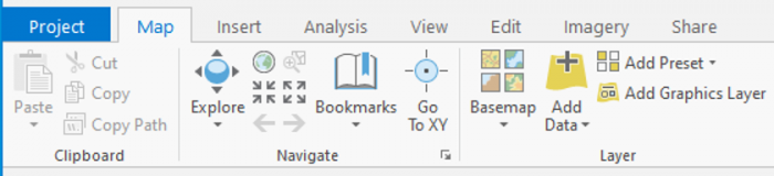 Credit: 2021, ArcGIS [100]
The Add Data Window will open. You will have three options for finding data: (1) the project folder, (2) portal (online), and (3) my computer.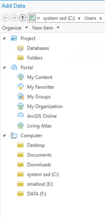 Credit: 2021, ArcGIS [100]
 -
In the pane of the window, under my computer click on the folder that you have saved the data files in. If you have used the default location for saving the project (C:\Users\Yourname\Documents\ArcGIS\Projects), the geodatabase is inside the UniversityParkCampus folder.
-
Go inside the geodatabase and Double-click the following layers to add them to the map: UP_BUILDINGS,UP_Major_Roads, UP_Minor_Roads, UP_Sidewalks, and UP_TREES.
Attention: if you go to the project folder you can see that a geodatabase named exactly as your project has been created: “UniversityParkCampus.gdb’.This is the geodatabase that you will use for saving the results of the analysis. The geodatabase that we have given you (Lesson5.gdb) contains external data prepared for you to start.
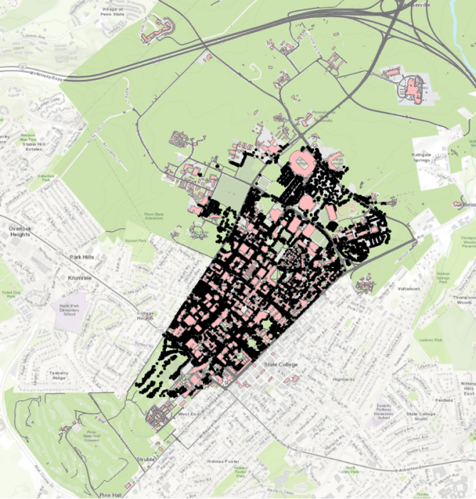 Credit: ChoroPhronesis Lab [41]
The map will center on the University Park campus in State College, PA.
1.3 Navigate the Map and Create Bookmarks
1.3 Navigate the Map and Create Bookmarks
Before we focus on symbolizing the layers and improve the map, you will learn how to navigate the map and create bookmarks to quickly return to key areas.
- On the top of the page, a ribbon is located. On the Map tab, in the Navigate group, click the ‘Fixed Zoom Out’ button. The map zooms out a fixed distance.
You can also zoom by positioning your mouse pointer in the map window and using the mouse’s scroll wheel.
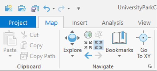 Credit: 2021, ArcGIS [100]
 - Zoom out until you see the entire campus area.
- In the map tab, in the Navigate group, click the Explore button.
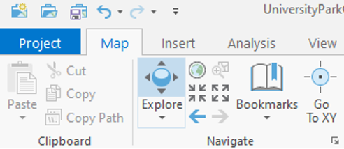 Credit: 2021, ArcGIS [100]
 - Click and drag the map to pan to the west side of campus where the IST (Information Sciences and Technology) building is located.
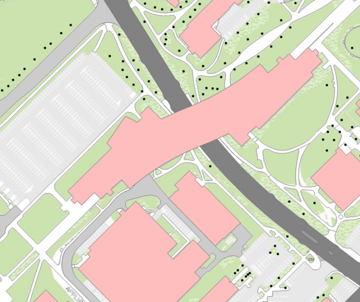 Credit: ChoroPhronesis Lab [41]
 - Pan back to the center of the University Park campus.
Now, you will create bookmarks to quickly and efficiently navigate to points of interest. - In the Map tab, in the Navigate group, click the bookmarks button and choose a new Bookmark.
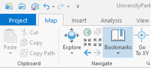 Credit: 2021, ArcGIS [100]
 - Type University Park for the Bookmark Name. Click OK.
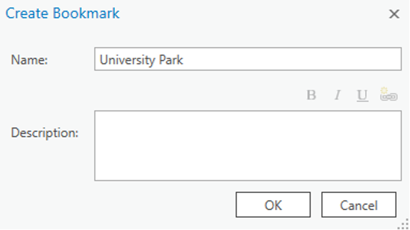 Credit: 2021, ArcGIS [100]
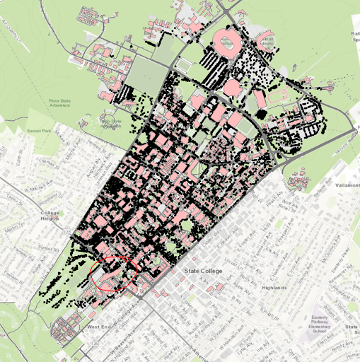 Credit: ChoroPhronesis Lab [41]
 - Zoom back to the IST building highlighted below. To zoom to a specific extent, press and hold the Shift key and draw a box around the area on the map.
 Credit: ChoroPhronesis Lab [41]
 - Bookmark the IST building. Name the bookmark IST.
- Click the Bookmarks button and click the University Park bookmark.
- Click on the building pictured below to open a pop-up window with additional information.
Every feature has a pop-up window. By default, a pop-up displays the attribute data of the selected feature. The above example includes the building’s name and its construction year.
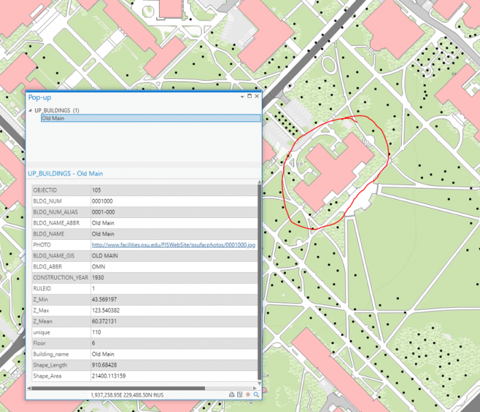 Credit: ChoroPhronesis Lab [41]
 - Bookmark this building and name it Old Main. You can also access the Bookmarks pane on the right side of your map to get an overview of the bookmarks you created.
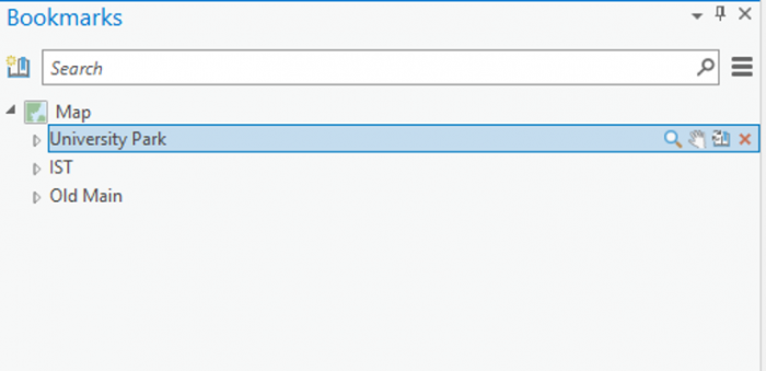 Credit: 2021, ArcGIS [100]
 - Click some of the buildings to learn about the data. You can find the Geography Department and the Hub and bookmark them for practice.
- Return to the University Park bookmark. In the Quick Access Toolbar at the top corner of the ribbon, click the Save button to save your project.
 Credit: 2021, ArcGIS [100]
In the next lesson, you will learn about data symbolization and editing.
Section Two: Symbolize Layers and Edit Features
Section Two: Symbolize Layers and Edit Features
Introduction
You probably noticed during your map-exploration that it was hard to distinguish some of the features because of how they were symbolized. In this section, you will symbolize your map, for example, to enhance readability.
2.1 Symbolize the UP_BUILDINGS layer
2.1 Symbolize the UP_BUILDINGS layer
First, you'll give the buildings layer a more appropriate color.
- If necessary, open the UniversityParkCampus project in ArcGIS Pro.
- On the contents pane, uncheck all layers but UP_BUILDINGS. Click the colored rectangle symbol under the UP_BUILDINGS layer.
The Symbology pane opens to the Gallery.
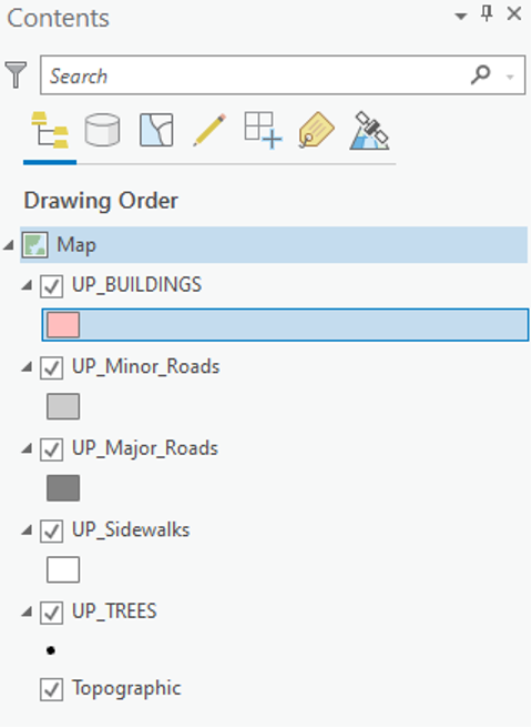 Credit: 2021, ArcGIS [100]
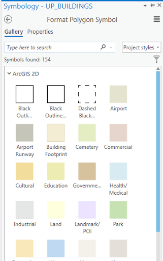 Enter caption hereCredit 2021, ArcGIS
 - In the search box, type sienna and press Enter.
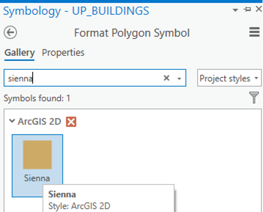 Credit: 2021, ArcGIS [100]
 - The result is that the symbology for buildings will change to orange-brown. Feel free to explore further color options.
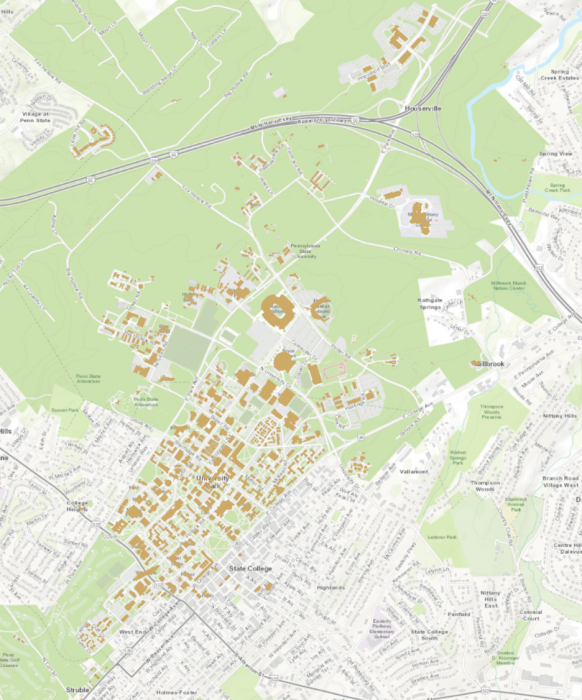 Credit: ChoroPhronesis Lab [41]
2.2 Symbolize the UP_Major_Roads and UP_Minor_Roads layers
2.2 Symbolize the UP_Major_Roads and UP_Minor_Roads layers
Next, you will change the major roads symbol.
- On the Contents pane, turn on the UP_Major_Roads layer. Click the colored rectangle symbol under the UP_Major_Roads.
- On the Symbology pane, click Properties.
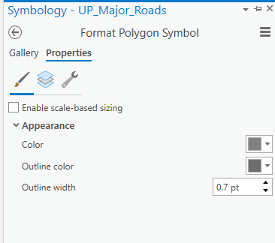 Credit: 2021, ArcGIS [100]
 - Under Appearance, click the drop-down arrow next to Color and choose Gray 50%. For the outline color, choose no color.
Hover over a color to see its name.
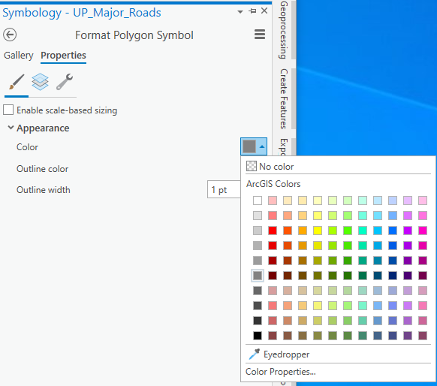 Credit: 2021, ArcGIS [100]
 - At the bottom of the Symbology pane, click Apply.
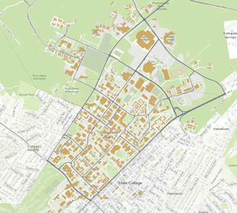 Credit: ChoroPhronesis Lab [41]
Repeat the previous steps for UP_Minor_Roads. Change Minor roads’ symbol to ‘Gray 40%’ with no outline color.
2.3 Symbolize the UP_Sidewalks
2.3 Symbolize the UP_Sidewalks
Next, you will change the UP_Sidewalks.
- On the Contents pane, turn on the UP_Sidewalks. Click the colored rectangle symbol under the UP_Sidewalks.
- On the Symbology pane, click Properties.
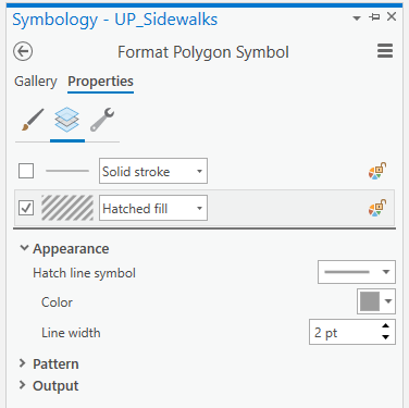 Credit 2021, ArcGIS
 - Under Appearance, click the drop-down arrow next to Color and choose Gray 40%. For the outline color, choose no color.
- Then click on the Layers tab. Un-check the first option, which is for outline style. Click on the second option and choose hatched fill.
For the hatch line symbol, choose simple stroke (2.0 pt). Hover over to see its name.
Choose 2.5 pt for the line width.
- At the bottom of the Symbology pane, click Apply.
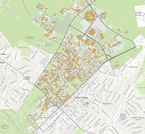 Credit: ChoroPhronesis Lab [41]
2.4 Symbolize UP_TREES
2.4 Symbolize UP_TREES
Trees in Up_Trees are point features. Here we will show you how to symbolize point features based on attributes. Before symbolizing this layer, explore the attribute table for this layer.
- On the Contents pane, turn on UP_TREES. Right-click the UP_TREES layer and click on the Attribute Table.
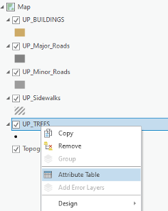 Credit: 2021, ArcGIS [100]
 - Examine the fields in the attribute table.
This tree layer is extracted from LiDAR Imagery collected in 2015. Some of the trees species are existing trees from a 2005 survey. Some have been added to the database as new trees and some are best guesses based on the LiDAR data. Therefore, tree type, listed as ‘symbol’ is only available for some but not all trees. A new tree database is under development for a complete tree database. You can see different tree symbols, such as deciduous and evergreen. You will symbolize the tree layer based on the symbol field.
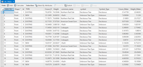 Credit: 2021, ArcGIS [100]
 - Close the attribute table.
- Click the point under UP_TREES. The Symbology pane will appear on the left side.
- At the top of the page, a ribbon is located. Click on the appearance tab.
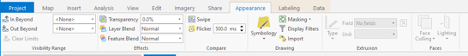 Credit: 2021, ArcGIS [100]
 - Click the drop-down arrow under Symbology and select ‘Unique Values’ under ‘Symbolize your layer via categories’. Now you can see that the symbology pane on the left side has changed to unique values.
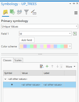 Credit: 2021, ArcGIS [100]
 - Change the value field from Id to symbol. Now you can see different values under symbol attribute.
There are three types of deciduous and three types of evergreen and one ‘Unknown Tree Type’ value. Null values belongs to new trees which do not have tree symbol assigned to them. We would like to group all deciduous trees together and all evergreen trees together.
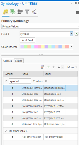 Credit: 2021, ArcGIS [100]
 - Select all three categories for deciduous trees and group them. Do the same for evergreens.
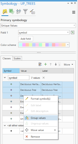 Credit: 2021, ArcGIS [100]
 - Click on the label values (last column) and change the values to Deciduous, Evergreen, and Unknown, respectively.
- Now select Format symbol for deciduous category.
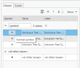 Credit: 2021, ArcGIS [100]
 - For the evergreen symbol, under Layers, choose shape maker from the menu. This time instead of Font, click on Style tab.
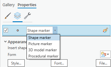 Credit: 2021, ArcGIS [100]
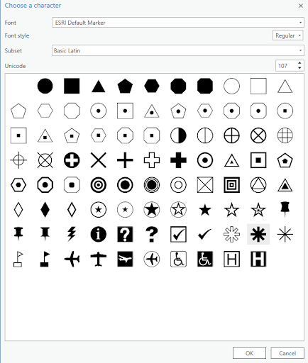 Credit: 2021, ArcGIS [100]For color, choose Tarragon green, and for the outline color black. The outline width should be 0.2 opt and the symbol size, 13 pt.
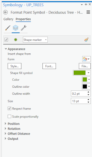 Credit: 2021, ArcGIS [100]
 -
For the evergreen symbol, under Layers, choose shape maker from the menu. This time instead of Font, click on the Style tab.
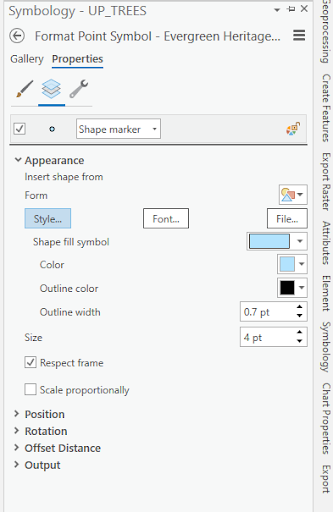 Credit: 2021, ArcGIS [100]
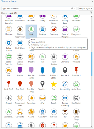 Credit: 2021, ArcGIS [100]
Based on the screenshot, choose Fir Green for the color, and 18 pt for the symbol size.
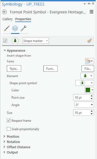 Credit: 2021, ArcGIS [100]
 -
For the unknown symbol, under Layers, choose shape maker from the menu.
Then click Font and choose shape 107 and click ok.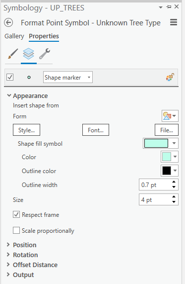 Credit: 2021, ArcGIS [100]Based on the screenshot, choose Medium Olivenite for the color, no color for the outline color and 0.01 pt for the outline width, and finally 13 pt for the symbol size.
 Credit: 2021, ArcGIS [100]Click apply on the bottom of the pane.
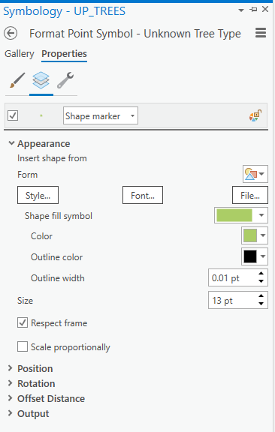 Credit: 2021, ArcGIS [100]
To make the trees more visible, you can drag the layer on top of the layers in Content pane. The final result would be like the following image: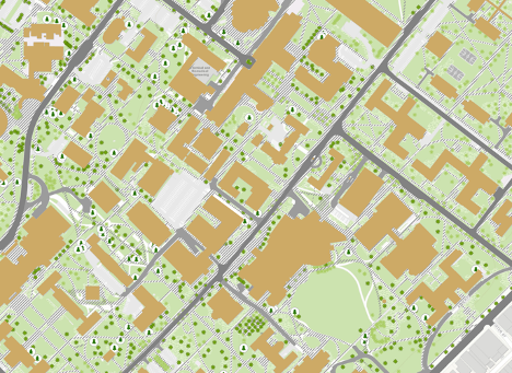 Credit: ChoroPhronesis Lab [41]
 - Make a Screenshot of UP Campus with all symbolized layers for your graded assignment. This is labeled Task 1 on the Tasks and Deliverables.
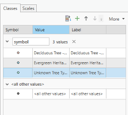
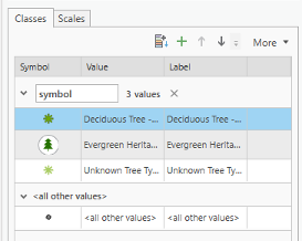
Section Three: Explore Raster Data
Section Three: Explore Raster Data
Introduction
To present a 3D scene of University Park Campus, you need an elevation base for your building footprints and other layers such as roads and trees. In this section, we focus on preparing the Digital Elevation Model (DEM) for University Park Campus. The Digital Elevation Model (DEM) is a bare earth elevation model. It has been extracted from LiDAR data.
3.1 Add and Explore Raster Data
3.1 Add and Explore Raster Data
In the previous section, you worked with feature data, data displayed as discrete objects, or features. While feature data is great for depicting buildings, roads, or trees, it is not the best way to depict elevation over a continuous surface. To do that, you'll use raster data, which can demonstrate a continuous surface. Raster data is composed of pixels, each with its own value. Although it looks different from feature data, you add it to the map in the same way.
- If necessary, open the University Park Campus project in ArcGIS Pro.
- In the Map tab, in the Layer group, click the Add Data button.
- In the Add Data window, under My Computer, navigate to where you have saved the data. Double-click UP_BareEarth to add it to the map.
- In the Contents pane, uncheck the boxes next to all layers, leaving only UP_BareEarth, UP_Buildings, and the basemap visible.
The elevation unit is feet. Unlike the feature layer, which has shape geometry, raster layer use pixel matrices in which each pixel stores its own value. The layer resolution, the size of its pixels or cell size (x,y) is 2 by 2 square feet. The result, 4, means that each pixel represents an area of four square feet.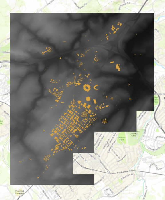 Credit: ChoroPhronesis Lab [41]
 - In the Contents pane, click the arrow next to UP_BareEarth to view its symbology.
Instead of a single symbol, this layer has a color scheme for different values. The values represent elevation in feet. The elevation ranges from about 825 feet above sea level (black) to about eighteen hundred feet above sea level (white).
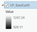 Credit: 2020 ArcGIS [100]
 - On the Map tab, in the Navigate group, click Explore. Click anywhere on the raster to open a pop-up window.
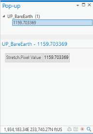 Credit: 2021, ArcGIS [100]
The pop-up shows the Pixel Value, which indicates the actual value of a pixel. In this raster, it shows the elevation. In the above image, the selected pixel has an elevation of about 1159 feet above sea level.
- Close the pop-up.
3.2 Smoothing the DEM and Creating Contours
3.2 Smoothing the DEM and Creating Contours
Before exploring the raster data in 3D, we need to smooth the elevation model, so the 3D model of campus fits the elevation model nicely. In order to monitor the level of smoothness of a DEM, creating contours can be helpful. A contour set built based on a raw digital elevation model (DEM) data can show minor variations and irregularities in the data. Creating a smooth contour set for topography is helpful in smoothing the data.
Note: the smooth grid should not be used for any analysis that requires raw DEM. For instance, building height cannot be extracted from a smoothed DEM.
- At the top of the page, a ribbon is located. Click on the analysis tab.
 Credit: 2021, ArcGIS [100]
 - In the Geoprocessing group, click Tools.
- In the Geoprocessing pane, search ‘Focal Statistics’.
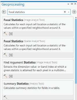 Credit: 2021, ArcGIS [100]
 - Select the Focal Statistics, which is located under Spatial Analyst Tool.
The Focal Statistics tool will resample from the DEM and apply a search distance defined by cells or model distance.
- Choose UP_BareEarth as the input raster. Name the output raster so you can remember it! Every smoothed grid should be named and documented with information describing the smoothing process. The default name is FocalST_UP_B1. It means focal statistics phase 1.
- Select Circle from the drop-down next to Neighborhood and set the smoothing Radius to 3. Leave all other default settings. Specify MEAN as the Statistics type.
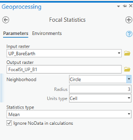 Credit: 2021, ArcGIS
 - Click Run on the bottom of the pane to create the first smoothed grid.
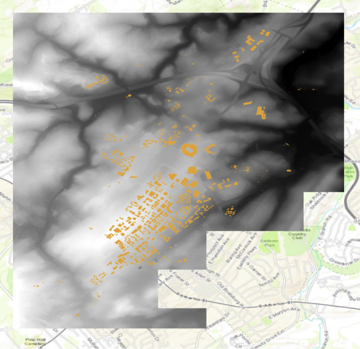 Credit: ChoroPhronesis Lab [41]
 - Contour lines can be created from this smoothed grid. Go back to the search bar in the Geoprocessing pane and search contour. Select contour with Barriers (Spatial Analyst Tool).
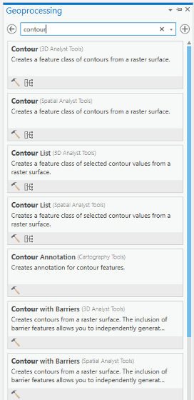 Credit: 2021, ArcGIS [100]
 - Select FocalSt_UP_B1 as the Input raster and specify the output contour feature as FocalSt_UP_B1_Contour1. Types of Contour will be polyline. Set the Contour Interval to 5 feet and Indexed Contour Interval to 20 feet. Leave default values for other options. Click Run to create the contours.
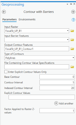 Credit: 2021, ArcGIS [100]
 - When the contours have been drawn, zoom in and inspect them. Notice that these lines are quite dense, especially when the entire model is viewed. Open the attribute table and verify that approximately 2,310 contour lines were created. These contours range in elevation from
930 to 1245 feet.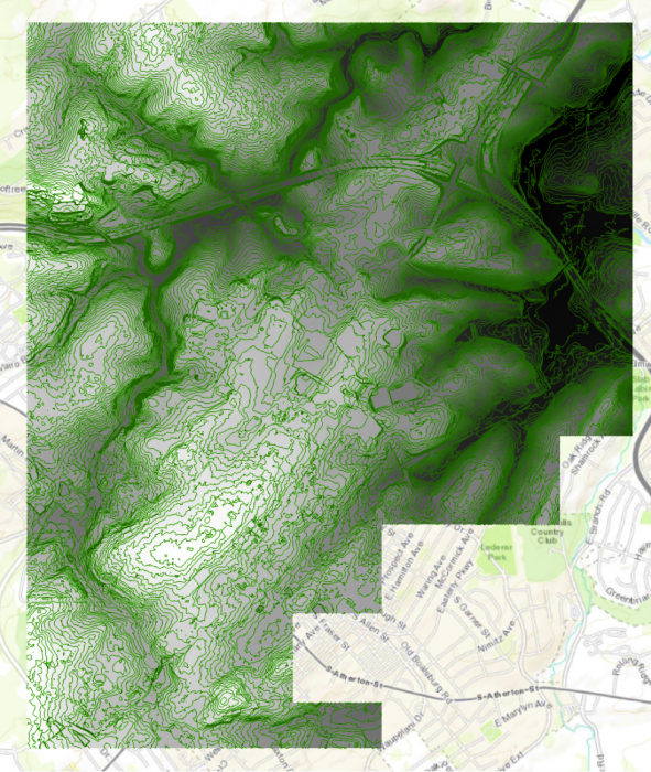 Credit: ChoroPhronesis Lab [41]
 - We can symbolize the indexed contour to have a better sense of elevation. Click the contour layer in the contents pane. Click the appearance tab. Under Symbology, select unique values. On the Symbology Pane symbolize based on value field “Type”. Type 1 are contours, which are every 5 feet and type 2 are barriers, which are every 10 feet.
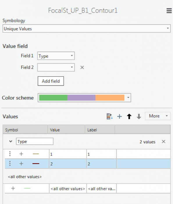 Credit: 2016 ArcGIS [100]
 - As you learned in the previous section, select symbology for each type. When you click format symbol, you can either choose Gallery (choose from preexisting styles) or choose Properties. We suggest properties.
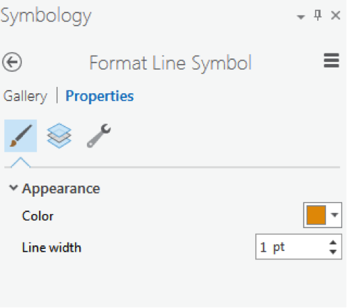 2016 ArcGIS [100]
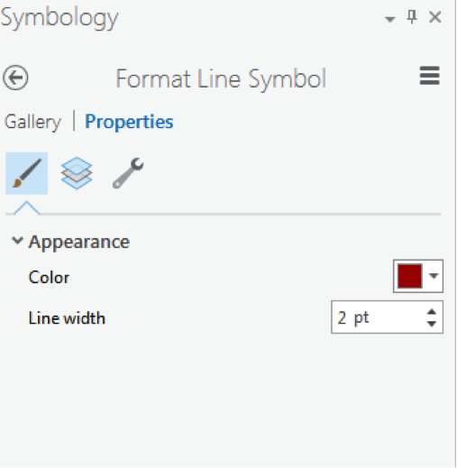 Credit: 2016 ArcGIS [100]
 -
Click the contour layer in the contents pane. Make sure the symbol is highlighted by clicking on it. From the top ribbon, under Feature Layer, click Labeling. Under Label Class group, choose Contour for Field value. For class value click on the SQL button.
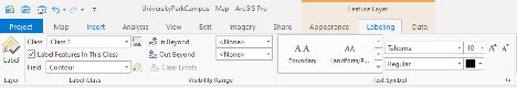 Credit: 2021, ArcGIS [100]
 - In Label Class pane, under SQL, click New Expression. Choose Type is equal to 2. With this selection, you will only label indexed contours. Click Apply.
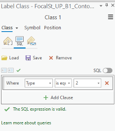 Credit: 2021, ArcGIS [100]
 - Go back to the labeling tab on top of your map. Choose font Corbel, size 12, bold, black.
- Click Label button under Layer group.
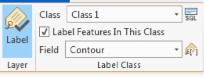 Credit: 2016 ArcGIS [100]
 - Your final result should look like this image.
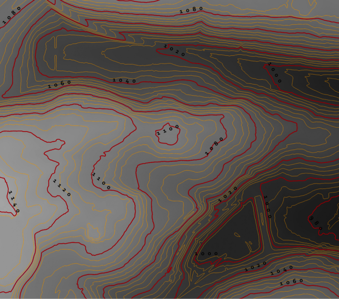 Credit: ChoroPhronesis Lab [41]
 - Keep this contour layer for comparison with the final result.
- To have a smoother DEM, you have to repeat step 5 to 7 for a few times (Focal Statistics). Let’s say 12 times. Every time, you have to use the previous smoothed DEM. For instance, for the second round, you will use ‘FocalSt_UP_B1’ as an input. Keep the same naming system and options. Name the second output as FocalSt_UP_B2. You do not need to create contours for every smoothed layer. You will create another contour layer for the last output ‘FocalST_UP_B12’ to compare it with the first result.
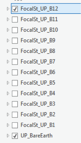 Credit: 2016 ArcGIS [100]
 - Now that you have the final DEM Layer (FocalST_UP_B12), Create Contour with Barriers for it. Repeat step 11 to 15. You can see how much smoother the new contours are. It means that we have a smooth DEM that is easier to work with.
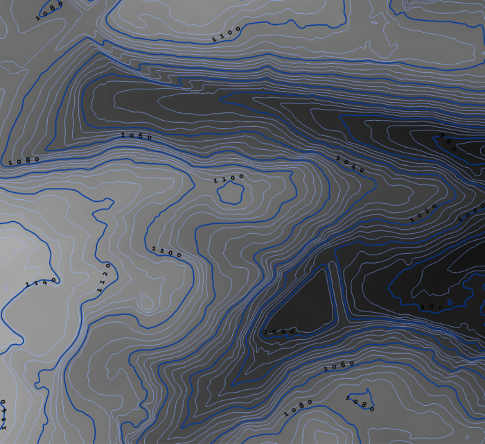 Credit: ChoroPhronesis Lab [41]
 - By choosing another color for the ‘FocalSt_UP_B1_Contour12’, you can compare the smoothness with the first created contour layer. You can choose light blue for the contours and dark blue for index contour. Repeat the labeling process to label your contours.
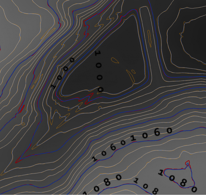 Credit: ChoroPhronesis Lab [41]
 - Select ‘FocalSt_UP_B1_Contour12’ in the Content Pane. From the top ribbon, choose Data, under Raster Layer. Click Export Data.
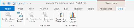 Credit: 2021, ArcGIS [100]
 - As input Raster, choose ‘FocalSt_UP_B12'. Rename the output Raster to Smoothed_DEM. Click Run.
You do not need the other raster/contour layers you created (from B1 to B12). You can remove them from your Contents pane. Also, remove UP_BareEarth. - For your final Assignment, you need a map of Smoothed_DEM and its full extent. Turn off all layers but Smoothed_DEM and Topographic. Zoom in or out, so that the DEM is in the center of your map.
- On top Ribbon, go to the Insert tab and add a new layout of A4 size. a layout page is opened.
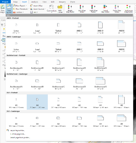 Credit: 2021, ArcGIS
 - On Insert tab, click Map Frame and select the map option with Scale.
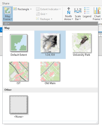 Credit: 2021, ArcGIS
 - Draw the frame on the A4 paper layout that you would like the map to appear.
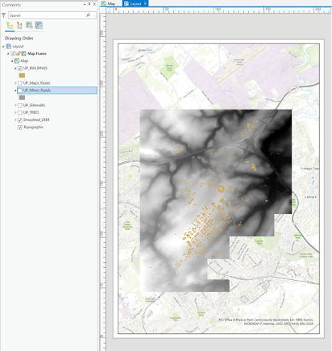 Credit: 2021, ArcGIS
 - Under Layout, right-click on Map Frame and click Activate. You can zoom in and out until get the desired scale. Also, on the bottom of the page you can enter the desired scale. When finished, click Layout on top ribbon and Close Activation.
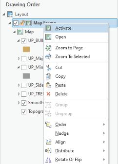 Credit: 2021, ArcGIS [100]
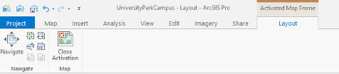 Credit: 2021, ArcGIS [100]
 - Under insert, click Legend on Map Surrounds.
 Credit: 2021, ArcGIS [100]
 - Draw the legend wherever you like on the Layout area. You can try to add a north arrow or scale bar if you are interested.
- Click the Share tab. Under Print click Layout. Select Adobe PDF and Print the results. This is labeled as Task 2 on the Tasks and Deliverables.
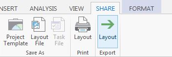 Credit: 2016 ArcGIS [100]
Section Four: Explore 3D Data
Section Four: Explore 3D Data
Introduction
In this section, you’ll visualize 3D data. You will learn how to convert a 2D map to 3D scene, visualize the DEM layer and other feature classes such as trees and buildings.
4.1 Convert a Map to a Scene
4.1 Convert a Map to a Scene
Most commonly we display data as a 2D map (although this may change in the future). Traditionally, in ArcGIS software, a 2D map was displayed in ArcMap and a 3D scene displayed by ArcScene.
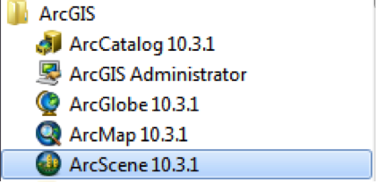
In ArcGIS Pro, you will have 2D maps and 3D scenes in the same platform. A scene is a map that displays data in 3D. By default, ArcGIS Pro will convert a map to a global scene, which depicts the entire world as a spherical globe. Since your area of interest is University Park Campus, not the entire globe, you will need to change the settings so the map converts to a local scene instead.
- Before starting this section, turn on UP_BUILDINGS and Smoothed_DEM layers.
- Click the Project tab.
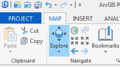 Credit: 2016 ArcGIS [100]
 - Click Options, on the blue pane.
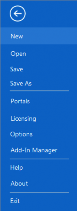 Credit: 2016 ArcGIS [100]
 - The Options window will appear. Under Application, click Map and Scene.
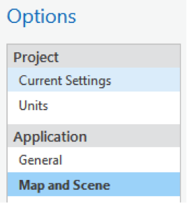 Credit: 2016 ArcGIS [100]
 - Choose the default base map of your organization.
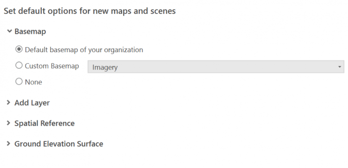 Credit: 2019 ArcGIS [100]
 - Click OK. In the blue pane, click the back arrow to return to your map.
- On the View tab, in the View Group, click Convert and from the drop-down menu choose ‘To Local Scene’.
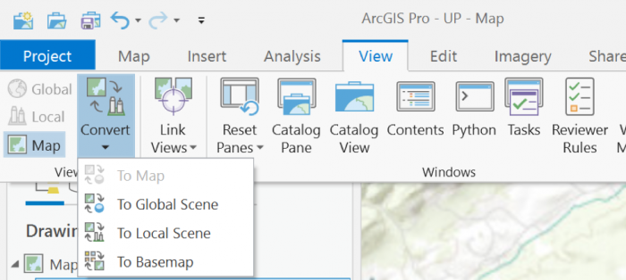 Credit: 2019 ArcGIS [100]
Your map converts to 3D, creating a new pane called Map_3D. You can go back to your 2D map at any time by clicking the Map tab.
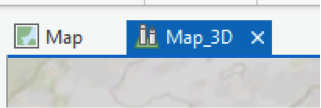 Credit: 2016 ArcGIS [100]
 - Under the Map_3D pane, still, your data is 2D and flat. This is because your layers are designed as 2D. You will change them later in this section. If the UP_BUILDINGS layer is in the 3D Layers, drag it down to 2D Layers.
- In the Map_3D scene, hold down the scroll wheel or the V key and drag the pointer to tilt and rotate the scene. Pan and zoom the same way you would in a 2D map.
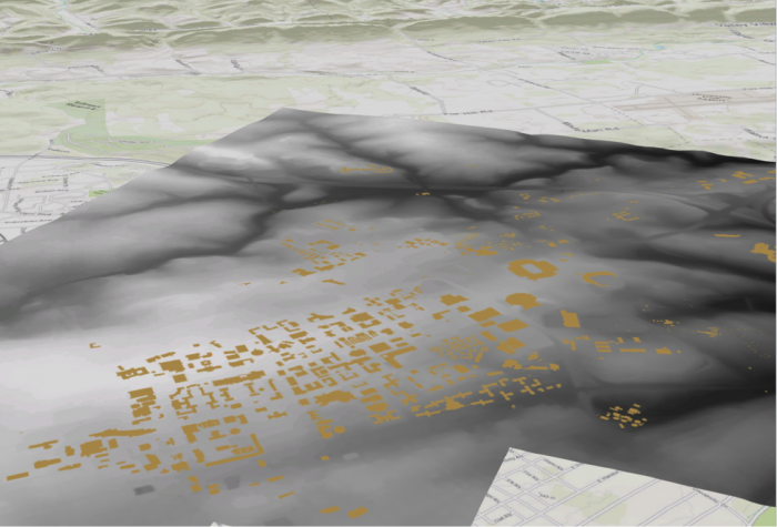 Credit: ChoroPhronesis Lab [41]
The flatness of the campus contrast with hills in the distance. By default, scene uses a map of elevation data, called an elevation surface, to determine the ground's elevation. It is a low resolution but spans the entire world.
- On the Map tab, in the Layer group, click the Add Preset button and choose Ground. The Add elevation source window opens. The Smoothed_DEM should be set as the ground in the area around campus. Navigate to the location of Smoothed_DEM. Click Select.
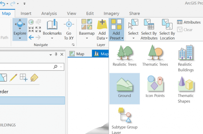 Credit: 2019 ArcGIS [100]
 - Pan, zoom, and tilt to navigate the scene and better view the new ground elevation. You may have to zoom very close to see the shifts in elevation.
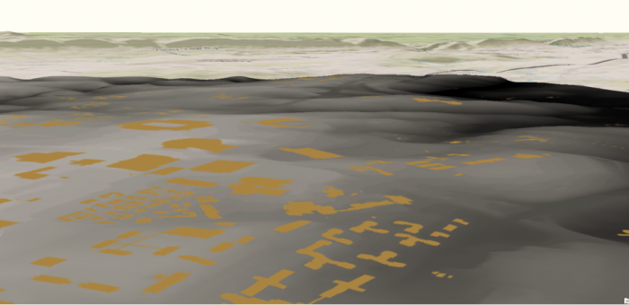 Credit: ChoroPhronesis Lab [105]
4.2 Extrude the UP_BUILDINGS Layer
4.2 Extrude the UP_BUILDINGS Layer
Another layer that is flat but should not be is the building footprint. The UP_BUILDINGS layer has height data in its attributes. It has been extracted from LiDAR data (as discussed in Lesson 4). To display the layer in 3D, you will use a command called extrusion, which displays features in 3D by using a constant or an attribute as the z-value. In this layer, the attribute will be Z_Mean.
- In the Contents pane, click and drag the UP_Buildings layer from the 2D Layers group to the 3D Layers group.
- Right-click on UP_BUILDINGS layer and select properties.
- Go to Elevation tab. Select the drop-down menu in front of ‘Features are’.
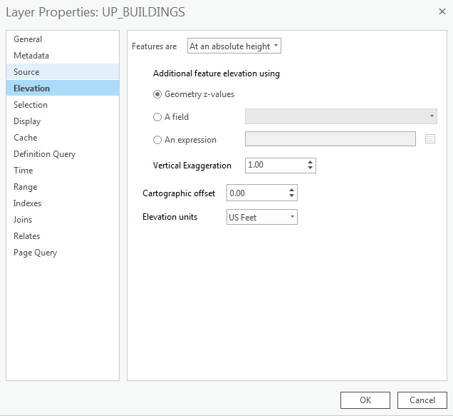 Credit: 2016 ArcGIS [100]
 - Select ‘On the ground’ option. This means that the buildings layer uses the DEM as the ground base for elevation. For ‘Elevation units’ choose US feet. Click OK.
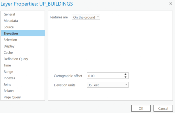 Credit: 2019 ArcGIS [100]
 - In the Contents pane, right-click UP_BUILDINGS and choose Attribute Table. Find the Z_Mean field. You will extrude the layer with values in this field.
- Close the attribute table.
- Make sure the UP_BUILDINGS is selected on the Contents pane.
- On the Appearance tab, in the Extrusion group, click the Type button and choose Max Height
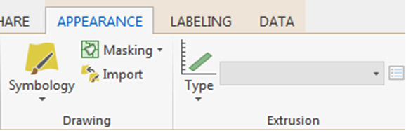 Credit: 2016 ArcGIS [100]
 - Click the menu next to Type and choose Z_Mean.
The features are extruded, meaning they are given a height value based on the selected field. They now appear 3D on the map.
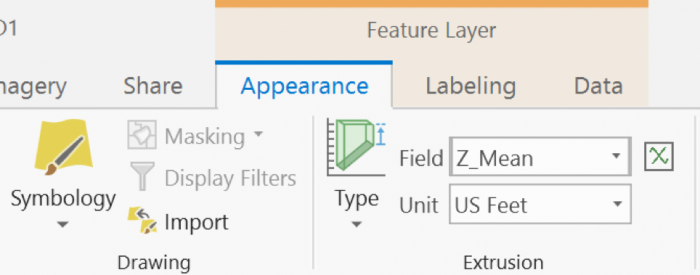 Credit: 2019 ArcGIS [100]
 - Turn off Smoothed_DEM Layer. Now, you can see the extruded buildings on top of the base map.
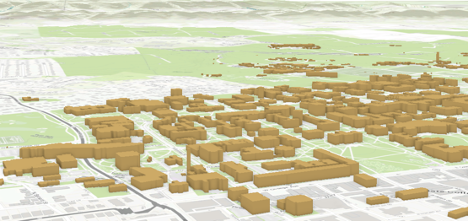 Credit: ChoroPhronesis Lab [41]
 -
Now you can turn on Roads and sidewalks. Make sure they are under 2D layers. Later in this Lesson, you will extrude trees and symbolize them.
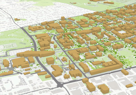 Credit: ChoroPhronesis Lab [41]
 - If you turn off the basemap (Topography), you will have a better view of the roads and sidewalks.
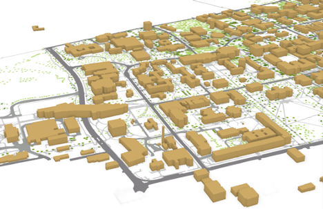 Credit: ChoroPhronesis Lab [41]
 - Save the Project.
Section Five: Display a Scene with More Realistic Details
Section Five: Display a Scene with More Realistic Details
Introduction
As you can see, the extruded buildings in the previous section, are blocks with no details, just the elevation. In this section, you will learn how to present part of west campus with more details. To do so, you should remove some of the features from UP_BUILDINGS that overlap with the layer that has more detailed information. This new layer (UP_Roof_Segments), that you will add to the map, consists of roof segments with detailed elevation. This information has been extracted from LiDAR data. In other words, instead of treating buildings as a big, undifferentiated chunk, every change in shape or elevation in each building has been detected and a new layer that represents those change/segments have been created. In Module 4, we have explained the process of creating this layer in detail.
5.1 Add and Extrude the UP_Roof_Segments
5.1 Add and Extrude the UP_Roof_Segments
In this section, you will remove the overlapping part of UP_BUILDINGS Layer with the P_Roof_Segment. This means that the UP_Roof_Segments represents part of campus with more details while UP_BUILDINGS will represent the rest of the campus (where the detailed model is not available) with less detail.
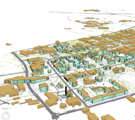
Therefore, you should remove the overlapping feature from UP_BUILDINGS Layer. This means that the UP_Roof_Segments represents part of campus with more details while UP_BUILDINGS will represent the rest of the campus (where the detailed model is not available) with less detail.
- On the contents pane, uncheck UP_BUILDINGS Layer.
- On the Map tab, in the Layer group, click the Add Data button.
 Credit: 2016, ArcGIS [100]
 - Add UP_Roof_Segments from the geodatabase (Module5.gdb) that you downloaded earlier in this Lesson.
- Right-Click on UP_Roof_Segment layer and select properties.
- Go to Elevation tab. Select the drop-down menu in front of ‘Features are’.
- Select ‘On the ground’ option. This means that the buildings layer uses the DEM as the ground base for elevation. Click OK.
- Click UP_Roof_Segment on the contents pane.
- On the Appearance tab, in the Extrusion group, click the Type button and choose Max Height.
 Credit: 2016, ArcGIS [100]
 - Click the menu next to Type and choose Z_Mean_Roof.
- Change the layer outline width to 0.3.
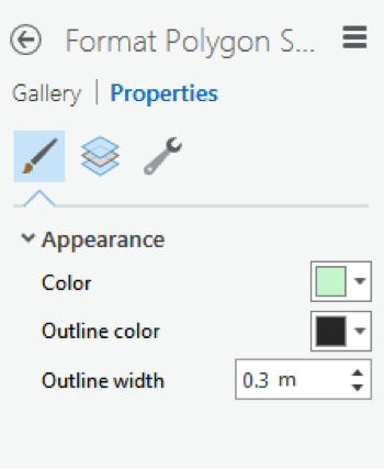 Credit: 2016 ArcGIS [100]
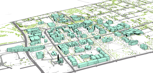 Credit: ChoroPhronesis Lab [41]
This is how your model should look like. You can navigate by holding down the scroll wheel or the V key and drag the pointer to tilt and rotate the scene. You can see the level of details each building presents in 3D.
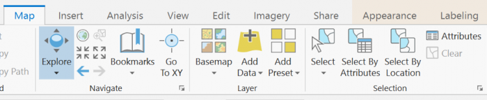 Credit: 2019, ArcGIS [100]
 -
To see how the buildings look like in reality, go to GoogleMaps [106]. Search for University Park Campus.
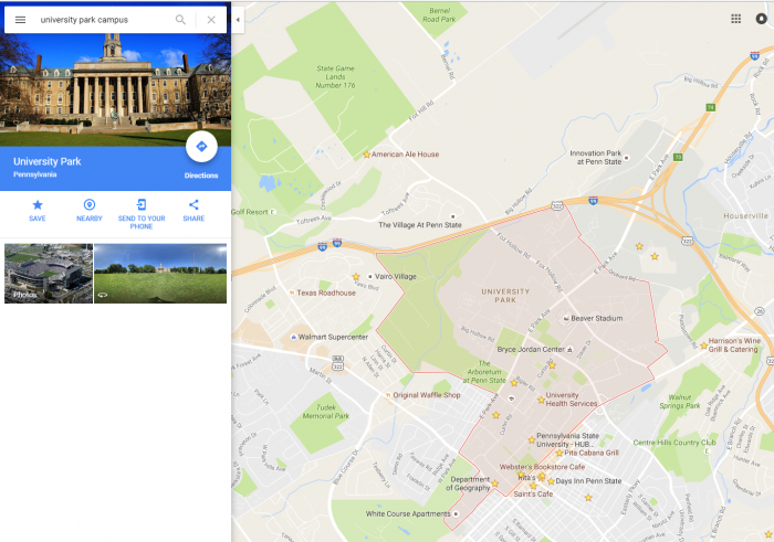 Credit: Google Maps [107]
Click the earth option at the bottom of the page.
 Credit: Google Maps [107]
Your map will turn to Earth view.
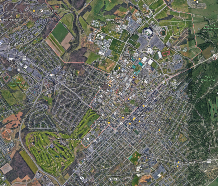 Credit: Google Maps [107]
Zoom in to Penn State Alumni Association. This is how the roofs structures look like:
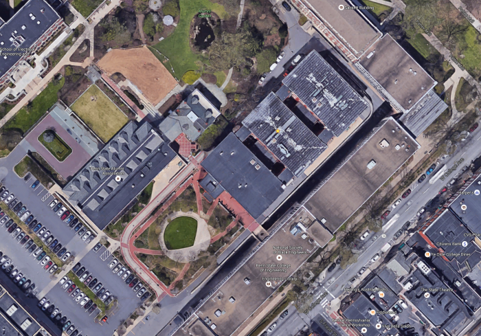 Credit: Google Maps [107]
Go back to your ArcGIS Pro project and find the same building. You can find the same level of detail in roof structure.
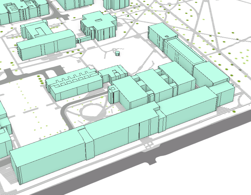 Credit: ChoroPhronesis Lab [41]
Go back to Google map and explore more. You see that some of the buildings have flat roofs and some shed roofs. However, in your 3D model, all the roofs are flat. You will add different roof types later in this module.
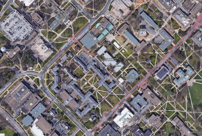 Credit: Google Maps [107]
 - Go back to ArcGIS Pro. In the content pane, turn the UP_BUILDINGS layer back on and make sure that it is located under the UP_Roof_Segments layer. In parts of campus which has both layers, the two layers are not overlapping well; this is because UP_Roof_Segments layer masking UP_BUILDINGS and has more details in the change of elevation than the UP_BUILDINGS Layer.
- In order to remove features from UP_BUILDINGS, you should select those features. The best way to do that is to select by location. On the Map tab, in the Layer group, click the ‘Select By Location’ under Selection group.
- You will select features from UP_BUILDINGS that intersect with UP_Roof_Segments. Therefore, choose the factors as shown in the image below. Click Run.
- If you uncheck the UP_Roof_Segments layer, you can see the part of UP_BUILDINGS that has been selected. This is the part that overlaps the UP_Roof_Segments.
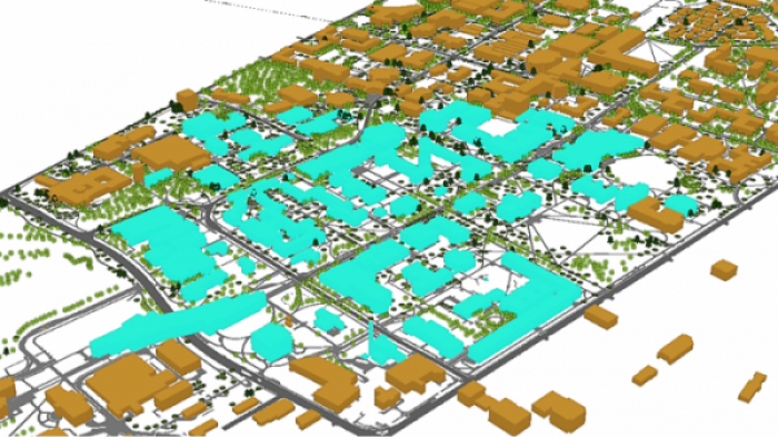 Credit: ChoroPhronesis Lab [41]
However, what you need to keep is the rest of the buildings, not what has been selected. Therefore, you will switch selection to select the remaining part of the campus.
- Right-click on Up_BUILDINGS. Under Selection, choose Switch Selection.
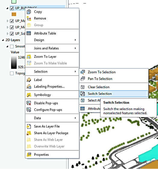 Credit: ChoroPhronesis Lab [41]
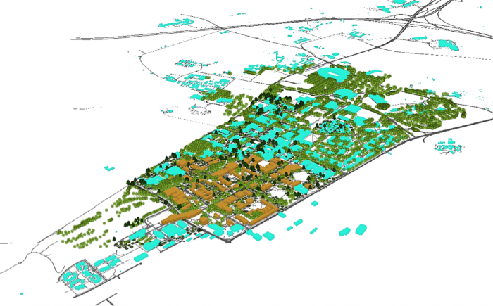 Credit: ChoroPhronesis Lab [41]
 - Now, you will export the selected features. Right-click on UP_BUILDINGS layer and click Data, choose Export Features.
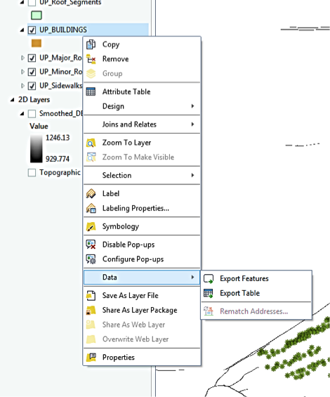 Credit: 2016 ArcGIS [100]
 - Rename the output features to ‘Building_Footprints’. And click Run.
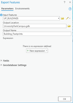 Credit: 2020, ArcGIS [100]
 - On the contents pane, uncheck UP_BUILDINGS Layer. Click Building_Footprints on the Contents pane.
- If the Building_Footprints layer is not extruded,in the Appearance tab, in the Extrusion group, click the Type button and choose Max Height. Click the menu next to Type and choose Z_Mean.
 Credit: 2016, ArcGIS [100]
 - Turn the UP_Roof_ Segments layer back on. Your map should look like this:
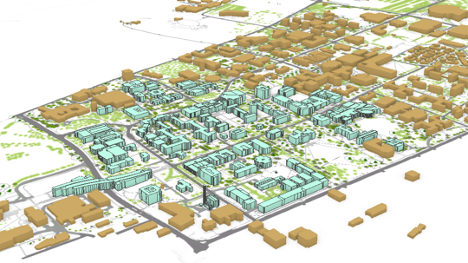 Credit: ChoroPhronesis Lab [41]
 - Save your project.
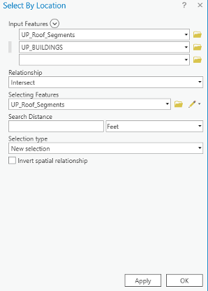
5.2 Apply a Rule Package to the UP_Roof_Segments Layer
5.2 Apply a Rule Package to the UP_Roof_Segments Layer
In this section, you’ll add special 3D textures and models to your scene to give it a more realistic appearance. The symbology of the structures is presentable in 3D but doesn't give the impression of a realistic city model. For instance, types of roofs, roof textures or façade textures, are not defined in this type of 3D presentation. To make the campus look more realistic, you can set the layer's symbology with a rule package created in CityEngine (see Lesson 2). Rule packages contain a series of design settings that create more complex symbology. Although you cannot create rule packages in ArcGIS Pro, you can apply and modify them from an external file (more in the next lessons).
- Download Building_From_Footprint rule package [104].
- Locate the compressed file in your Downloads folder. Save the file in the project folder you have created earlier in this Module. It is a single file named Building_From_Footprint.rpk.
- If necessary, open the University Park Campus project in ArcGIS Pro.
- In the Contents pane, click the symbol under UP_Roof_Segments to open the Symbology pane.
- In the Symbology pane, click Properties and click the Structure button.
Structure presents symbol layers, or graphical components, that create a symbol.
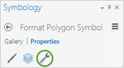 Credit: 2016, ArcGIS [100]
For the UP_Roof_Segments, the only symbol layer is the light green solid color you have used. To add a rule package to the Symbology, you will create a new symbol layer to which a rule can be applied. - In the drop-down menu in the heading of the symbol layer, choose fill layer
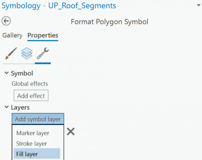 Credit: 2019, ArcGIS [100]
 - Next, you will apply the rules to the Fill symbol layer using the file you downloaded. Under Properties, click the Layers button. Then, select the Procedural fill. Uncheck the line and green color.
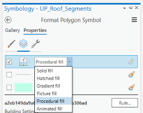 Credit: 2021, ArcGIS [100]
 - The icon from a gray solid color would be changed to an icon indicating a rule assignment. Click the Rule button and Browse to the location of the extracted Building_From_Footprint.rpk file and double-click it. The Symbology pane populates with several symbology settings or rules, that can be adjusted.
- Click apply.
- On the Symbology pane, you need to set rules. Because the rules that are created in CityEngine are based on metric parameters, we have created fields with metric values in the Up_Roof_Segments attribute table.
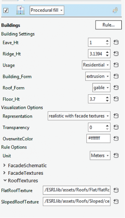 Credit: 2016, ArcGIS [100]
 - As you can see, next to each parameter is a ‘set attribute driven properties’ sign. Click to set values from the attribute table.
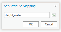 Credit: 2021, ArcGIS [100]
 - Eva_Ht is the distance from the ground to the bottom of the roof. Select Height_Meter from the attribute table.
- Ridge_Ht is the distance from the ground to the top of the roof. Select Ridge_Height_Meter. It is mostly applicable to the slopped roof.
- For Usage select educational. You can see switching from another usage like residential to educational, the thumbnail on the bottom of the pane will change.
- Building_From, select extrusion.
- Change the Floor_Ht to 4.
- You will have three options for visualization: (1) realistic with façade textures, (2) schematic facades, (3) solid colors. For now, choose the first option and you will explore the rest later. Click Apply.
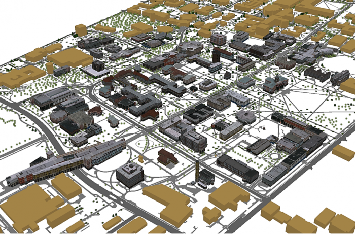 Credit: 2016, ArcGIS [100]
 - Explore the map to get a closer look at the symbology. Roof symbols and Façade symbols. As you see the façade material does not match the actual buildings you can see on Google Earth. That’s because real images of buildings of campus have not been taken. These images are from ESRI library for an international city which is a sample library with different building size and usage textures. The roofs are texturized base on some categories: flat, hip, shed, or pyramid. There is an asset folder of different roof textures and façade textures that are used in setting these rules. For instance, one of the Hip roof colors that you see in the following image. It has been assigned to Hip roofs along with a few more textures.
 Credit: 2016, ArcGIS [100]
 - Save your project.
5.3 Apply a Rule Package to UP_TREES Layer
5.3 Apply a Rule Package to UP_TREES Layer
In this section, you will insert a 3D model of trees with assigned rules. In your 3D Scene, you can see that 2D symbols of trees are presented in 3D. One of the ways to show your trees in 3D is to use LiDAR information such as crown diameter and tree height along with CityEngine procedural rules. However, ArcGIS Pro does not support assigning rule packages to point layers on the Symbology pane, yet. ArcGIS Pro is under constant development and will offer this functionality in the future. A workaround is to export the tree point layer as Polygons with Z information. Then the polygons can be converted to points. The point feature class with Z information and inherited rules can be added to your map as a preset.
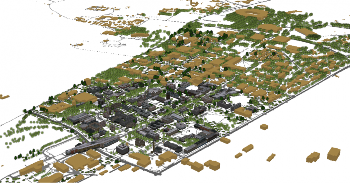
- Uncheck the Up_TREES layer in the 3D Layers list.
- Under the Map tab, click Add Preset and select Realistic Trees.
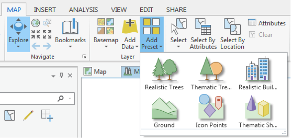 Credit: 2016, ArcGIS [100]
 - From the Geodatabase that you have downloaded, select CE_trees_Realistic. Click Select.
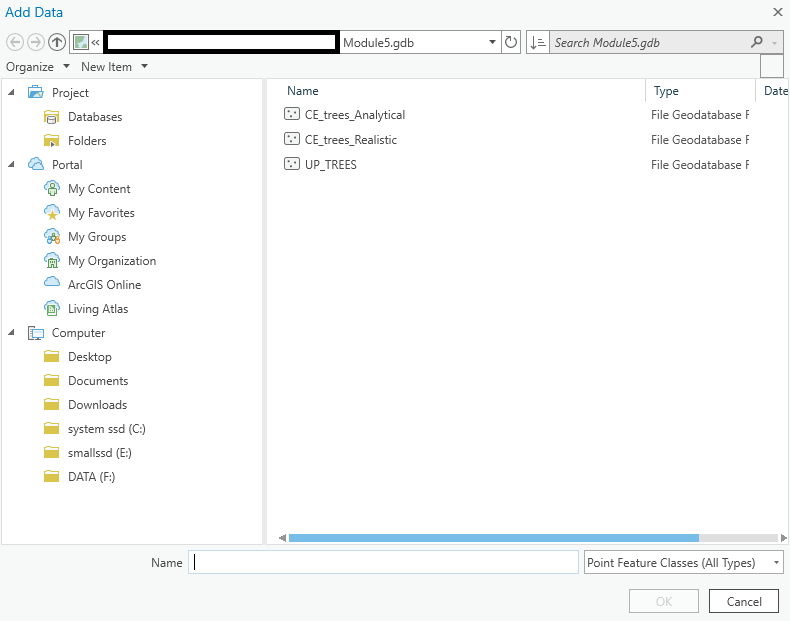 Credit: 2016, ArcGIS [100]
 - The layer will be added to your 3Dlayers list.
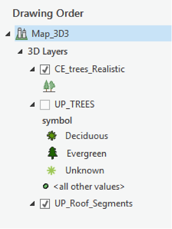 Credit: 2016, ArcGIS [100]
 - As you see on the map, the scale of trees is not right. Click on the symbol under the layer to modify it. Change the parameters as shown below.
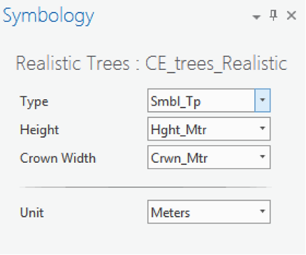 Credit: 2016, ArcGIS [100]
 - As you can see the trees height and crown diameter are now more realistic. You have three tree types under Smbl_TP: Deciduous, Evergreen, and Unknown. The unknown trees should be symbolized white as ghost trees. Unfortunately, both evergreens and unknown trees are colored white, although you can see that evergreen trees have a different shape than deciduous ones. If you change the type from Smbl_TP to Ash, for instance, you can see all trees are changing. You can try different tree types. We will update this section when the feature becomes available in ArcGIS Pro.
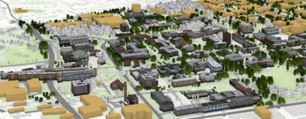 Credit: ChoroPhronesis Lab [41]
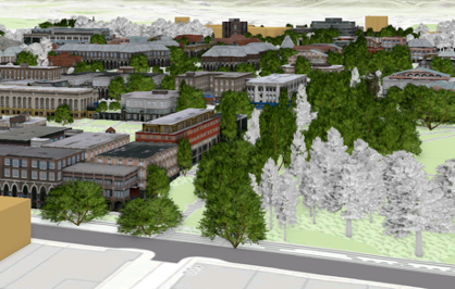 Credit: ChoroPhronesis Lab [41]
 - In the image above, you can see how the trees are symbolized in GIS. In CityEngine (as an example shown below), you can see that not only deciduous and evergreen trees are different but also various tree types under each category are symbolized differently. ESRI is continuously moving functionality from CityEngine to ArcGIS Pro so that it is hopefully only a matter of time that this function becomes available. We are not focusing on CityEngine in this course but will offer you an overview of how it works using the campus data as an example.
You can see the example of tree symbols used in CityEngine to symbolize trees. This vegetation library is imported from LumenRT 3D Plants to CityEngine.
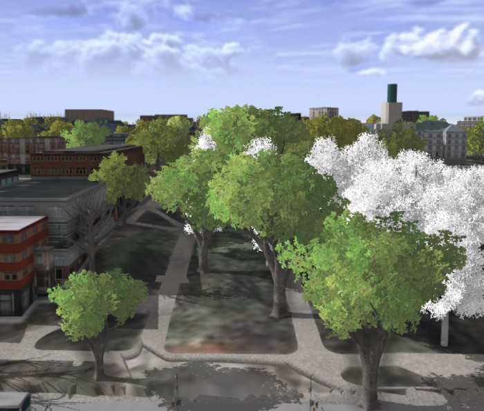 Credit: ChoroPhronesis Lab [41]
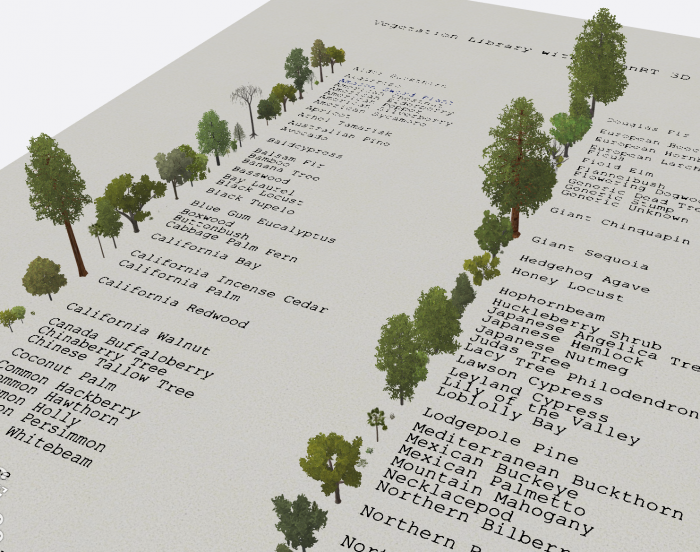 Figure: 3D vegetation with LumenRT ModelsCredit: ESRI/LumenRT vegetation library for CityEngine [92]
 - Create a PDF map (like the end of Section 3) or take a screenshot of your UP Campus realistic 3D model for the final assignment. This is labeled Task 3 on the Tasks and Deliverables of your graded assignment.
- Now you will save your project with a relevant name.
- Click the Project tab. Select Save As.
 Credit: 2016, ArcGIS
 - In the Projects Folder (C:\Users\YOURUSER\Documents\ArcGIS\Projects\UniversityParkCampus), Save Project as UniversityParkCampus_Lesson5. This way you will create a new project for the next lesson.
5.4 Change the Symbology from Realistic to Analytical
5.4 Change the Symbology from Realistic to Analytical
You have learned how to apply a rule package symbology to buildings to demonstrate a realistic view of campus. For some types of 3D analysis, an analytical demonstration may suffice. For the next Module, you will need an analytical presentation of campus. In this section, you will learn how to switch from realistic to analytical. In the next lesson, you will learn examples of 3D spatial analysis and you will need these analytical 3D models for the analysis.
- Click the Project tab. Select Save As.
Credit: 2016, ArcGIS [100]
- In the Projects Folder (C:\Users\YOURUSER\Documents\ArcGIS\Projects\UniversityParkCampus), Save Project as UniversityParkCampus_Lesson6. This way you will create a new project for the next lesson.
- Go back to the Map view.
- Uncheck the CE_trees_Realistic.
- Click on symbology under UP_Roof_Segments. On the Symbology pane, click Properties and select Layers.
- Change representation from realistic with façade textures to schematic facades.
Click apply.
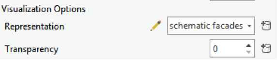 Credit: 2016, ArcGIS [100]
 - Your campus model should look like the following image:
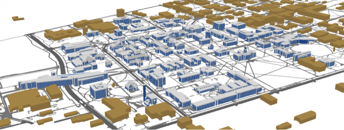 Credit: ChoroPhronesis [41]
 - Now, you will add thematic trees. On Map tab click Add Preset and select thematic trees.
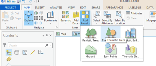 Credit: 2016, ArcGIS [100]
 - From the Geodatabase that you have downloaded, select CE_trees_Analytical. Click Select.
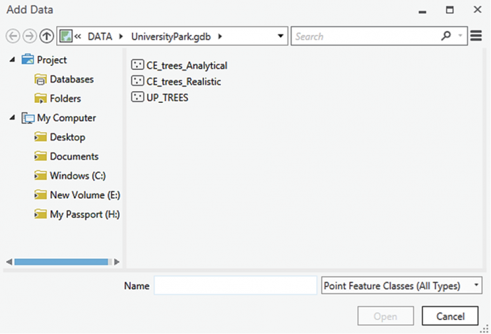 Credit: 2016, ArcGIS [100]
 - The layer will be added to your 3Dlayers list.
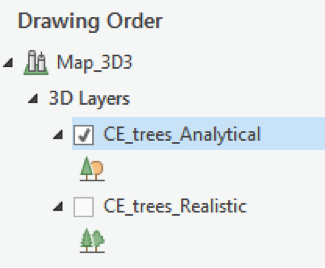 Credit: 2016, ArcGIS [100]
 - As you see in the map, the scale of trees is not right. Click on the symbol under the layer to modify it. Change the parameters as shown below.
As you see, one of the factors is color by value. Select random Seed and the green color ramp. This will give your trees a more colorful presentation.
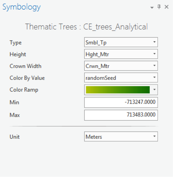 Credit: 2016, ArcGIS [100]
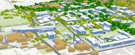 Credit: ChoroPhronesis [41]
 - Create a PDF map (like the end of Section 3) or take a screenshot of your UP Campus schematic 3D model for your graded assignment. This is Task 4 on the Tasks and Deliverables page.
- Save the project.
In this lesson, you learned how to work with ArcGIS Pro from creating a map and symbolizing layers to exploring raster and 3D data. You also learned about symbolizing 3D layers with rule packages from CityEngine. In the next lesson, you will learn about some 3D analysis that is possible with 3D data.
Tasks and Deliverables
Tasks and Deliverables
Assignment: ArcGIS Pro adn 3D modeling
This assignment has 3 parts, but if you followed the directions as you were working through this lesson, you should already have most of the last part done.
Part 1: Submit Your Deliverables
If you haven't already submitted your deliverable for this part, please do it now. You need to turn in all four of them to receive full credit. You can paste your screenshots into one file or zip all of the PDFs and upload that. Task 2 will need to be a PDF, so either way, you will have two files to zip.
- Task 1: a screenshot of all layers symbolized for UP Campus (end of Section 2)
- Task 2: print a PDF map of Smoothed_DEM Layer with a legend showing the minimum and maximum elevation (end of Section 3).
- Task 3: print a PDF map of your 3D campus with realistic facades and trees or simply create a screenshot (end of Section 5.3)
- Task 4: print a PDF map of your 3D campus with schematic facades and analytical trees or simply create a screenshot (end of Section 5.4)
Grading Rubric
Grading Rubric Criteria Full Credit No Credit Possible Points Task 1: Screenshot of all layers symbolized for UP Campus correct and present 1 pt 0 pts 1 pt Task 2: PDF map of Smoothed_DEM Layer with a legend showing the minimum and maximum elevation correct and present 1 pt 0 pts 1 pt Task 3: PDF map of your 3D campus with realistic facades and trees or simply create a screenshot correct and present 1 pt 0 pts 1 pt Task 4: PDF map of your 3D campus with schematic facades and analytical trees or simply create a screenshot correct and present 1 pt 0 pts 1 pt Total Points: 4
Part 2: Participate in a Discussion
Please reflect on your 3D modeling experience, using ArcGIS Pro; anything you learned or any problems that you faced while doing your assignment as well as anything that you explored on your own and added to your 3D modeling experience.
Instructions
Please use Lesson 5 Discussion (Reflection) to post your response to reflect on the options provided above and reply to at least two of your peer's contributions.
Please remember that active participation is part of your grade for the course.
Due Dates
Your post is due Saturday to give your peers time to comment. All comments are due by Tuesday at 11:59 p.m.
Part 3: Write a Reflection Paper
Instructions:
Once you have posted your response to the discussion and read through your peers' comments, write a one-page reflection paper on your experience in 3D modeling with the following deliverables as a proof that you have completed and understood the process of 3D modeling for Campus.
Due Dates
Your assignment is due on Tuesday at 11:59 p.m.
Submitting Your Deliverables
Please submit your completed paper and deliverables to the Lesson 5 Graded Assignments.
Grading Rubric
| Criteria | Full Credit | Half Credit | No Credit | Possible Points |
|---|---|---|---|---|
| Paper clearly communicates the student's experience developing the 3D model in ArcGIS Pro | 5 pts | 2.5 pts | 0 pts | 5 pts |
| The paper is well thought out, organized, contains evidence that student read and reflected on their peer's comments | 5 pts | 2.5 pts | 0 pts | 5 pts |
| The document is grammatically correct, typo-free, and cited where necessary | 1 pts | .5 pts | 0 pts | 1 pt |
| Total Points: 11 |
Summary and Tasks Reminder
Summary and Tasks Reminder
In this lesson, you have learned how to symbolize 2D and 3D maps. You also have learned the differences between static modeling and procedural modeling. Most importantly, you practiced how to create a 3D model of elevation and how to incorporate City Engine procedural rule symbology into GIS.
Reminder - Complete all of the Lesson 5 tasks!
You have reached the end of Lesson 5! Double-check the to-do list on the Lesson 5 Overview page to make sure you have completed all of the activities listed there before you begin Lesson 6.
Lesson 6: 3D Spatial Analysis
Overview
Overview
Importance of 3D Models in Spatial Analysis
In the previous lesson, you created a 3D map of the University Park campus. You learned how to symbolize layers based on procedural rule packages. In this lesson, you will learn two types of 3D spatial analysis. First, you will demonstrate the buildings that are affected in the case of a thunderstorm and a flash flood in State College. Second, you will learn how to do Sun Shadow analysis. It will give you a visual sense of how different sun positions will create various shadow volumes in different directions. It is a useful tool for building design and understanding the sun’s path in a given coordinate and also for figuring out the surface area that a building shades during a day.
Learning Outcomes
By the end of this lesson, you should be able to:
- Understand the importance of 3D models in certain geoprocessing analysis
- Present an example of 3D/spatial analysis
- Analyze the visibility of buildings and locations
- Calculate line of sights
- Calculate viewsheds
- Create layers
- Explore panning, zooming, and tilting
- Choose buildings and search for them
- Apply rules to extruded features
- Calculate, for example, a flood layer
- Share your work on Google Earth
Lesson Roadmap
| To Read |
|
|---|---|
| To Do |
|
Questions?
If you have any questions, please post them to our "General and Technical Questions" discussion (not e-mail). I will check that discussion forum daily to respond. While you are there, feel free to post your own responses if you, too, are able to help out a classmate.
Section One: Flood Analysis
Section One: Flood Analysis
Introduction
In this section, you will determine which areas of campus are more affected by flooding, by creating a raster layer representing accumulated water resulting from a thunderstorm. You will use the analytical 3D scene you created in the previous Lesson to visualize the flooding. In this study, you will use a FEMA flood map to find out how much of campus might be affected by the 1-percent annual chance flood, which is referred to as 100-year flood1. You will buffer the floodways around campus to present the flood plain and calculate the campus area affected by the 100-year flood. The floodway data is downloaded from FEMA flood map service center2. On flood plains, if you consider that water accumulation or the height of the water is a constant value, other factors that affect which areas are more affected by the flood are dependent on various factors. Examples of these factors are land elevation, surface material (pervious or impervious surfaces), vegetation coverage, and surface condition (saturated or dry). In this study, we only consider elevation as a factor. Therefore, you will extrude the flood data to see which buildings or trees are more affected.
For more information, refer to FEMA: Flood Zones [108]
1.1 Exploring Digital Elevation Model
1.1 Exploring Digital Elevation Model
-
Download Lesson6.gdb [104] and unzip the file, then save it to the main project location.
(C:\Users\YOURUSER\Documents\ArcGIS\Projects\ UniversityParkCampus).
- Open UniversityParkCampus_Lesson6 Project in ArcGIS Pro.
- Click the Project tab. Select Save As.
 Credit: 2019 ArcGIS
 - In the Projects Folder (C:\Users\YOURUSER\Documents\ArcGIS\Projects\ UniversityParkCampus), Save Project as UniversityParkCampus_lesson6_Flood. This way you will create a new project for the first section of this lesson.
- Go back to the Map view.
- Turn on the Smoothed_DEM layer.
- To get a better idea of elevation around campus, click on the band color value under Smoothed_DEM. Then, on top ribbon, click on appearance and select symbology.
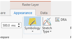 Credit: ArcGIS, 2021
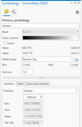 Credit: ArcGIS, 2021
Change the color scheme to Spectrum by Wavelength-Full Bright. You can turn on Show names to see the names on top of each color scheme.
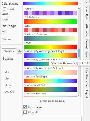 Credit: ArcGIS, 2021
 -
Go back to the Map_3D. Change the color scheme of Smoothed_DEM to Spectrum by Wavelength-Full Bright. Make sure that UP_Roof_Section and Building_Footprint layers are turned on. As you can see, the areas with higher elevations have warmer colors. It means that buildings located in the southern part of campus are more likely to be affected by flood, if we consider all the buildings in the same flood plain.
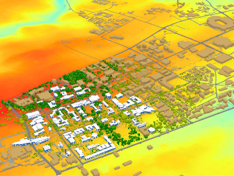 Credit: ChronoPhronesis Lab
1.2 Adding Flood Map Layer and Understanding the Attributes
1.2 Adding Flood Map Layer and Understanding the Attributes
- Click the Map tab to return to your 2D map.
- Turn off Smoothed_DEM.
- Turn on UP_BUILDINGS.
- Click add data. and from Lesson6.gdb, add FLD_HAZ_FEMA layer. Make sure it is located below UP_BUILDINGS in the Contents Pane.
-
Click to modify symbology. Under the Appearance tab, select Symbology and choose Unique Values.
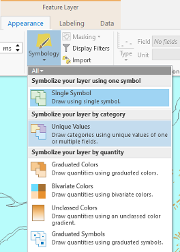 Credit: ArcGIS, 2021
 -
As you have learned in previous lessons, symbolize your layers based on FLD_ZONE to have good visualization of various values. Remove the outline for values.
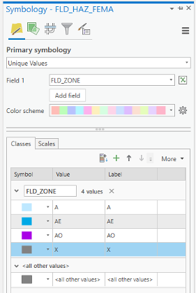 Credit: 2019 ArcGIS
 -
Zoom to UP_BUILDING layer. You should have a clear visualization of floodways with different categories.
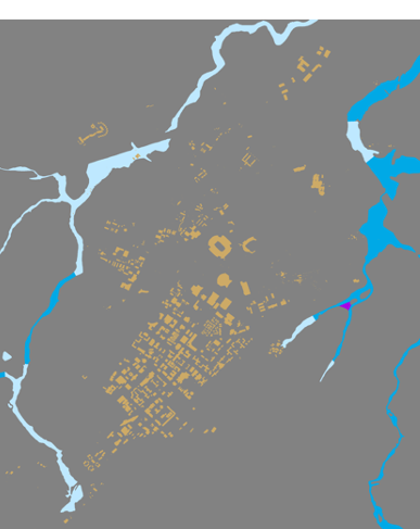 Credit: ChoroPhronesis Lab
Based on FEMA’s information3, categories A, AE, and AO are all 1-percent-annual-chance flood. A is determined using approximate methodologies. AE is created based on detailed methods. Finally, AO represents shallow flooding where average flood depths are between 1 to 3 feet. X represent areas that are not in a floodway. For this study, you are going to consider all three A, AE, and AO layers as one floodway category.
3FEMA: Flood Zones [108]
1.3 Extract Campus Area from FLD_HAZ_FEMA
1.3 Extract Campus Area from FLD_HAZ_FEMA
- Before creating flood plains, it would be better to select part of FLD_HAZ_FEMA layer that only contains the campus area.
-
The best way to create a boundary is to use Smoothed_DEM layer as the extent of the campus area. To be able to create a polygon out of a raster, you will need a raster with integer values. The current raster values are float. On the ribbon, on the Analysis tab, click Tools under Geoprocessing and search Int. Click Int (Spatial Analysis). The input layer is Smoothed_DEM and rename the output raster to DEM_int. Click Run.
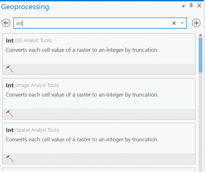 Credit: 2019 ArcGIS
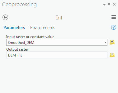 Credit: 2019 ArcGIS
 - Go back to geoprocessing tool and search raster calculator. To create a polygon without values, you need a raster with pixel value of 0.
-
Select Raster Calculator (Spatial Analyst Tools). Using Raster calculator, multiply DEM_int by 0 to create a constant value raster.
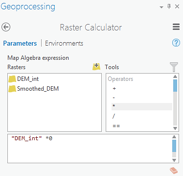 Credit: 2019 ArcGIS
Name the output raster as rasterzero. Click run. Now you have a raster with value of 0.
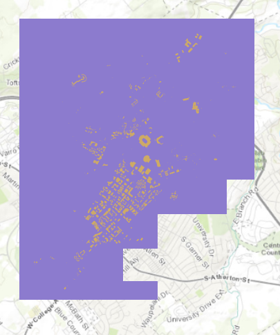 Credit: ChoroPhronesis Lab
 -
Go back to Geoprocessing Tools tab. Search or raster to polygon tool. Click Raster to Polygon (Conversion Tools). Convert rasterzero layer. Save the output polygon as Boundary. Click Run.
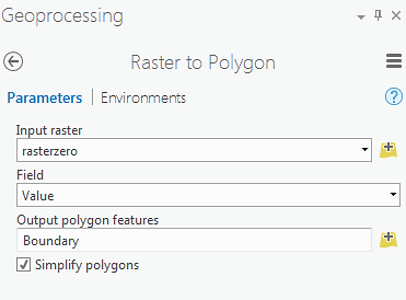 Credit: 2019 ArcGIS
 -
Remove rasterzero from Contents pane. You don’t need it anymore. Change the symbology of the Boundary layer to no fill, color with Tuscan Red, outline with the width of 2pt.
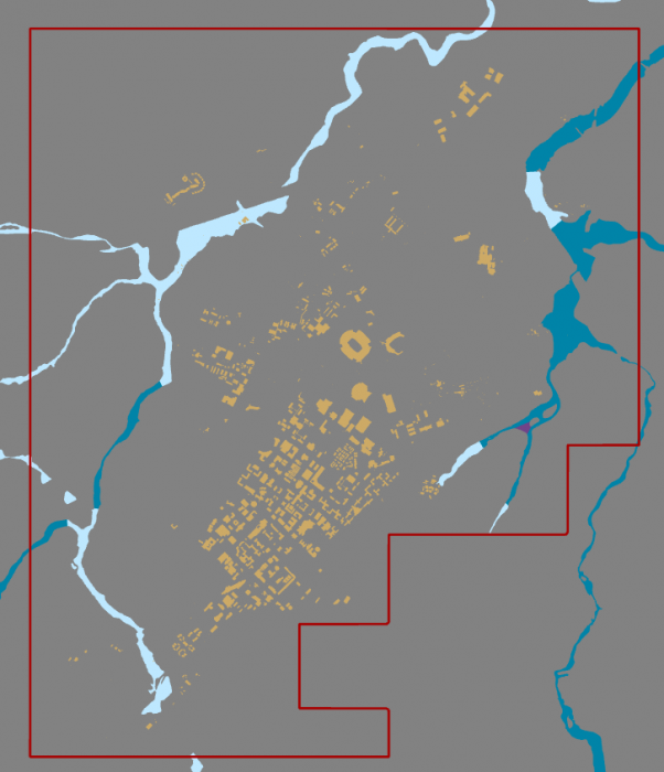 Credit: ChoroPhronesis Lab
 - Now that you have created the campus boundary, you will clip FLD_HAZ_FEMA layer. Go back to Geoprocessing Tools. Search clip. Click Clip (Analysis Tools). The input layer is the flood layer from FEMA (FLD_HAZ_FEMA). The Clip Feature is Boundary. Rename the out feature class to FLD_HAZ_Campus. Click Run.
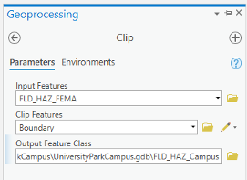 Credit: ChoroPhronesis Lab
 -
Turn off FLD_HAZ_FEMA. And make sure that FLD_HAZ_Campus is located under UP_Buildiing. This will be the result.
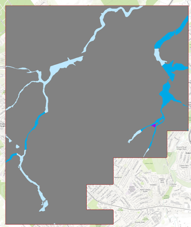 Credit: ChoroPhronesis Lab
1.4 Buffer the Floodways and Examine Potential Flood Extent
1.4 Buffer the Floodways and Examine Potential Flood Extent
For this study, you are going to consider all three A, AE, and AO layers as one floodway category.
-
On the ribbon, on the map tab, click select by attribute.
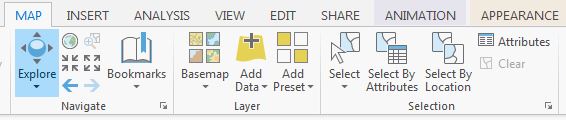 Credit: 2016 ArcGIS
 -
Under expression, add the following clause to select all three floodway categories:
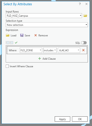 Credit: ArcGIS, 2021
Click Apply, then OK. All three floodway categories will be selected.
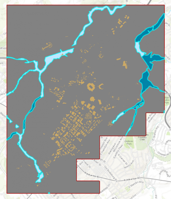 Credit: ChrorPhronesis Lab
Check Your Understanding
You have selected all the floodways on campus. Open the attribute table. Can you figure out how much the area of selected floodways are?
Click for the answer.15522969.81 square feet or 356.35 acre
This is how you can calculate the sum of the area:- Right-click on Shape_Area. Click Summarize.
- In the Geoprocessing tab, you can see the input and output tables. For Statistic Field, select Shape_Area. For the statistic Type select SUM. Click Run.
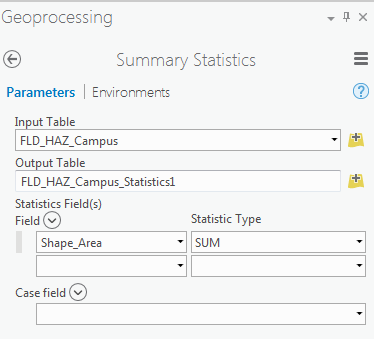 Credit: 2016 ArcGIS
 -
In Geoprocessing Tools, search buffer. Click Buffer (Analysis Tools).
Note: When you have selected features in a layer, the analysis will run only on selected parts. -
The input feature is FLD_HAZ_Campus. Name the output feature class as Flood_Extent. For the distance consider 1000 feet. This distance is just an example to teach you how the analysis works. It does not mean that the flood plain in this area is truly 1000 feet.
Set Side Type as ‘Full’, meaning that the buffer will be from both sides of floodways. Click Run.
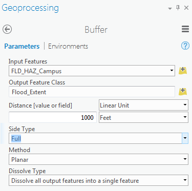 Credit: 2016 ArcGIS
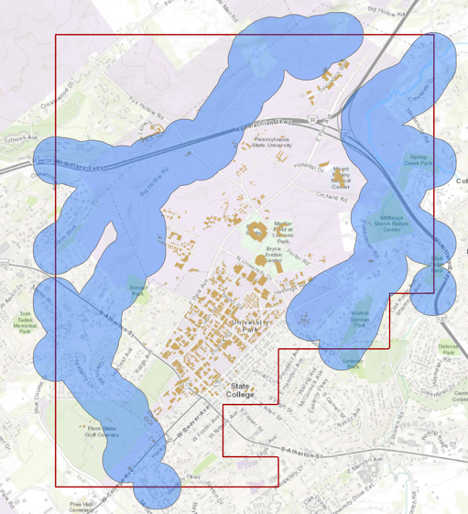 Credit: ChoroPhronesis Lab
 -
We are interested in the flood extent areas inside the boundary. The green areas are more affected than the rest of the campus. Now, you will create a polygon layer that has both areas: flood extent (1000 feet) and the rest of the campus. The proper tool to add the flood extent to the campus area is ‘Identity’. This tool computes geometric intersections of campus areas and flood plains. Those parts of campus overlapping with flood extent will get the attributes of identity features (flood extent).
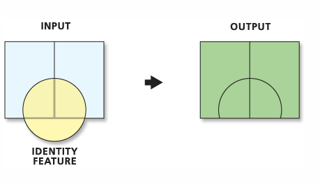 Credit: ArcGIS Pro [110]
 -
Before updating the flood zones of campus area, you need to clip the Flood_Extent, to extract areas inside the boundary. Go to Analysis tab, geoprocessing tools. Search Clip. Select Clip (Analysis Tools). Input feature is Flood_Extent. Clip Feature is Boundary. Name the output as Flood_Extent_Clip.
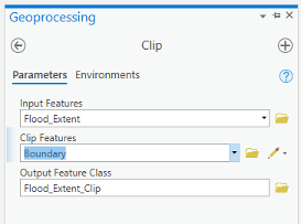 Credit: ArcGIS, 2021
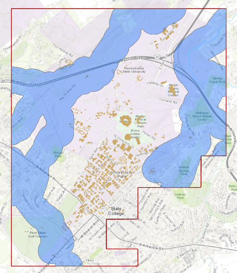 Credit: ChoroPhronesis Lab
 -
Turn off all layers. Go back to geoprocessing tools. Search update. Select Update (Analysis Tools). Input feature is Boundary, Update feature is Flood_Extent_Clip. Name the output feature class Flood_Zones_Campus. Click Run.
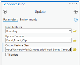 Credit: ArcGIS, 2021
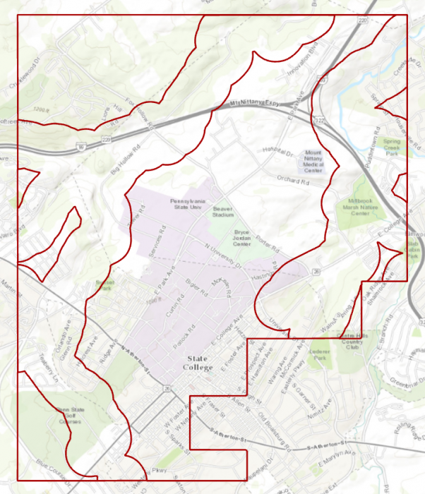 Credit: ChoroPhronesis Lab
 -
Right-click on Flood_Zones_Campus in Contents pane. Open Attribute Table. You can see there are two features in this layer with id categories 0 and 1. Select the row with id=0.
Check Your Understanding
What is the area of flood plain with higher risk (id=0) in acres?
Click for the answer.Approximately 2933.0 acres. Each square foot is approximately 2.295 acres.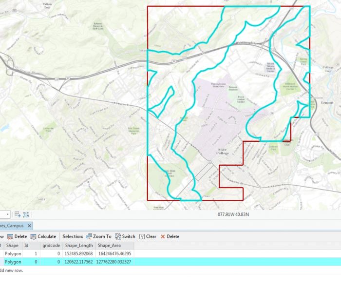 Credit: ChoroPhronesis Lab
The selected area is the 1000 feet extent from floodways and the rest is campus area with less flood risk in square feet.
- On the ribbon, on the Map tab, under selection category, click Clear.
1.5 Add Height Attribute Data to the Flood_Zone_Campus Layer
1.5 Add Height Attribute Data to the Flood_Zone_Campus Layer
As you can see in the attribute table, the layer that you have created does not have any height information. You need water height information to extrude the layer properly in the 3D scene. Therefore, you will add a new attribute to the table and give it desired values.
- In the Contents pane, right-click Flood_Zones_Campus and choose Attribute Table.
-
At the top of the attribute table, click the Field Add button. The Fields view opens, where you will be able to edit parameters.
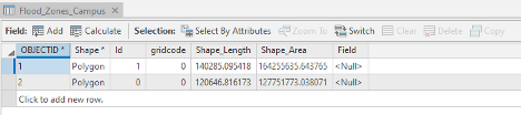 Credit: ArcGIS, 2021
 -
For the empty field at the bottom of the table, under Field Name, type Height. For Data Type, choose Float. Choosing Float over Integer allows you to have decimals.
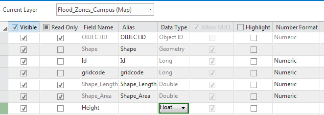 Credit: 2019 ArcGIS
 -
On the ribbon, on the Fields tab, click Save. The changes will be added to the table.
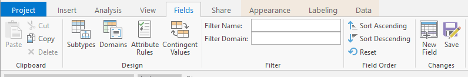 Credit: ArcGIS, 2021
 -
Close the Fields view. Return to the attribute table.
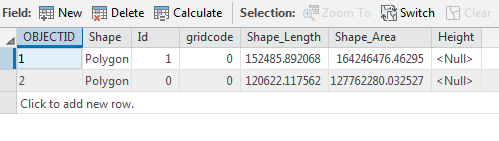 Credit: 2019 ArcGIS
 - Select the row with Id=0 by clicking the row.
-
On top of the attribute table click the Calculate field button.
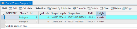 Credit: ArcGIS, 2021
 -
The input table is Flood_Zone_Campus. The field Name is Height. For the expression, you will consider 5 feet of flood for areas around the floodways. This number is for presentation purposes and is not accurate. Click OK.
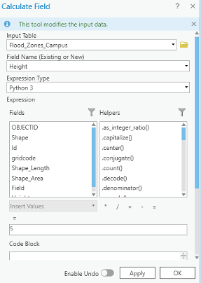 Credit: ArcGIS, 2021
 - Go back to the attribute table. Now you see the height value is 5.
- Click the second row with an id value of 1. Repeat the same calculate field step. This time Height =2 feet.
- Close the Calculate Field pane and the attribute table. Clear the selection.
1.6 Extrude the Flood_Zones_Campus Layer
1.6 Extrude the Flood_Zones_Campus Layer
- On the map tab, turn off the Topographic layer.
- Right- Click on Flood_Zone_Campus and select Copy.
- Click on Map_3D tab. Turn off Smoothed _DEM and WorldElevation3D/Terrain3D under Elevation surfaces/ Ground.
- Click on Map_3D in the contents pane and select paste. Flood_Zone_Campus will be added to your 2D_Layers.
-
To add it to the 3D scene, in the Contents pane, drag Flood_Zones_Campus from 2D Layers to 3D layers. Placing it below Building_Footprints. Make sure the other 2D layers are off.
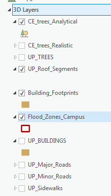 Credit: 2016 ArcGIS
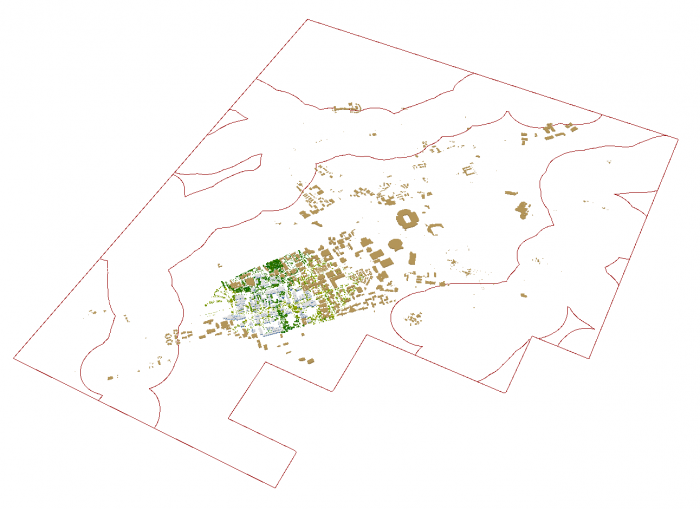 Credit: ChoroPhronesis Lab
 -
If you cannot see the layer, right-click on the layer and select properties. Click Elevation and make sure the Features are set as "on the ground".
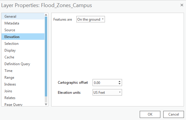 Credit: 2016 ArcGIS
 -
Click Flood_Zones_Campus. On the ribbon, click Appearance. Under Extrusion, choose Max Height as Extrusion Type. Select Height as the field of Extrusion. The Unit will be US Feet.
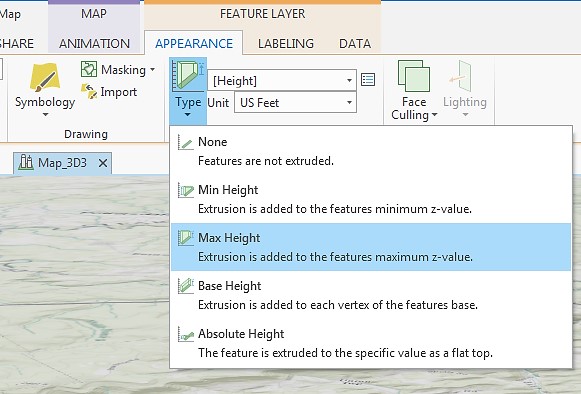 Credit: 2016 ArcGIS
 -
Click Flood_Zones_Campus. On the ribbon, click Appearance and from the Symbology drop-down menu choose Unique Values. In the Symbology pane, the value field is Id. Click Add all values. Change the color of id=0 as Apatite Blue with no border. The color for id=1 will be Sodalite Blue with no border.
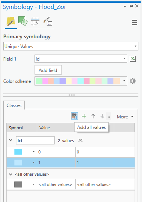 Credit: ArcGIS, 2021
 -
Again select the Flood_Zones_Campus. On the ribbon, click Appearance. On Effects group, change the transparency to 30 percent.
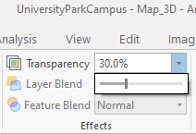 Credit: ArcGIS, 2021
 -
This will be the result:
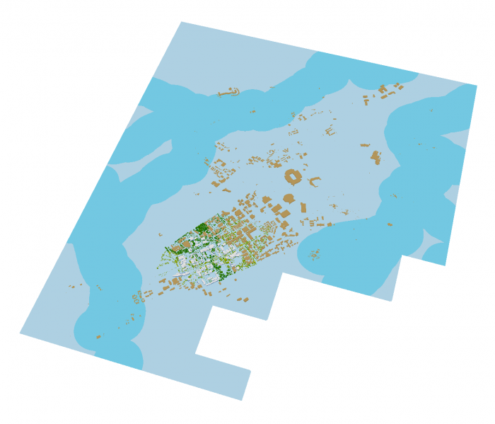 Credit: ChoroPhronesis Lab
 -
Using your mouse left click and V on the keyboard, navigate through the map. Zoom in to some buildings in different flood zones.
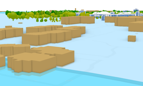 Credit: ChoroPhronesis Lab
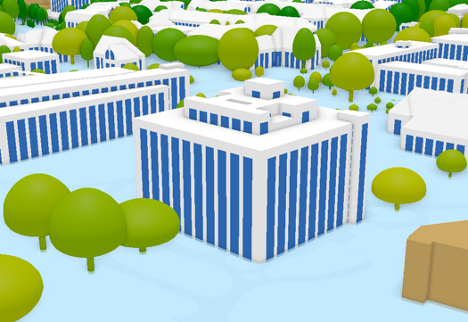 Credit: ChoroPhronesis Lab
You can see how less Walker building is flooded compared to peripheral buildings on campus. Changing the height information flood elevation, you can have different results. If you are curious to see how the visualization changes, change the attribute values of Height field in the attribute table.
- Make a Screenshot of OldMain in which the level of flooding can be seen. Paste your screenshot into Word and label it Task 1.
- Save the Project.
Section Two: Sun Shadow Volume Analysis
Introduction
Section Two: Sun Shadow Volume Analysis
Introduction
Shadow analysis is a tool that allows you to analyze daylight conditions by giving a certain date and time. It can be hourly analysis between sunrise and sunset or the changes in shadows at a certain time during different dates. It is a useful tool for building design and understanding the sun’s path in a given coordinate. Assume that you are a designer and you would like to design a high-performance building that its source of energy is solar. Also, the sun position and movement across your site play an important role in your design to benefit from the daylighting.
The most important questions would be how much does a building shade the surrounding area and how much does the surrounding area, such as buildings and trees, shade a building? It is obvious that trees’ shadows are desirable in summer and very important in cooling the environment, whereas in the winter the important factor in the environment is the shade created by buildings.
In this section, you will carry out the sun shadow analysis from sunrise to sunset in winter (January 1st, 2021). If you are interested you can carry out another analysis for summer (July 1st, 2021) to compare the results. Creating the shadow volumes, you will learn how to animate the shadow volumes that you have created.
2.1 Understanding 3D Features
2.1 Understanding 3D Features
- Open UniversityParkCampus_Lesson6 Project in ArcGIS Pro.
-
Click the Project tab. Select Save As.
 Credit: 2016 ArcGIS
 - In the Projects Folder (C:\Users\YOURUSER\Documents\ArcGIS\Projects\ UniversityParkCampus), Save Project as UniversityParkCampus_Lesson6_Shadow.
- Go back to the Map view.
-
Make sure the following layers are checked in the 3D Layers Content Pane: Up_Roof_Segments, Building_Footprints., and Topography.
Note: What you have created in Lesson 5 as a 3D building, is an extrusion from attribute. It means that you extruded a 2D polygon based on a ‘Z’ attribute you extracted from LiDAR Data or DSM or any other sources. Having an extruded building, does not make your features with 3D geometry. It is just a 3D visualization of your 2D data. For many 3D spatial Analysis, you need 3D features or Multipatch features.
3D features are features with 3D geometry. 3D features can be displayed without the need to draping them over a surface like DEM. They already have Z information in their geometry. In the image below you can see how 2D features (Crème color) are dependent on a surface for display in a 3D scene, whereas 3D features (Red color) have z information and are located in the elevation they belong to without extrusion.
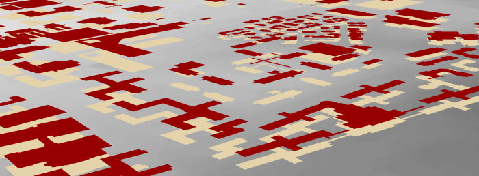 Credit: ChoroPhronesis Lab
Multipatch features are 3D objects that represent a collection of patches to present boundary (or outer surface) of a 3D feature. Multipatches can be 3D surfaces or 3D solids (volumes).
Also, the icon next to a multipatch feature is a 3D feature. The image below shows the multipatch icon. For now the only supported type of features for multipatch layers are polygons. Points and lines can be converted to 3D features but not multipatch features.
 Credit: 2016 ArcGIS
 - For ‘Sun Shadow Analysis’ you need multipatch features. Multipatch features for buildings are provided in Lesson6.gdb.
-
On the top ribbon, click Map and select Add Data. Locate Lesson6.gdb and select ‘Building_MP_Campus’.
Note: The reason that you will work on the smaller part of campus for this 3D spatial analysis is that your computer might not be able to handle bigger data. The multipatch layer for bigger areas of campus are also provided, in case you would like to carry on more analysis in your free time (Buildings_MP).
-
Right click on the symbol under layers to modify the color. Change the ‘Building_MP _Campus’ to Fire Red.
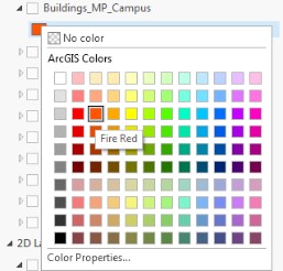 Credit: 2016 ArcGIS
 -
Right-click on Building_MP_Campus and select Properties. Select Elevation from the menu. Set the features are, Relative to the ground. Click Ok.
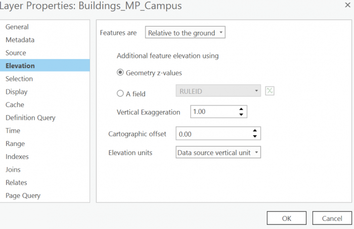 Credit: 2019 ArcGIS
 -
Uncheck UP_Roof_Segments. Now you can see what the multipatch surfaces look like. Navigate by holding down the scroll wheel or the V key and drag the pointer to tilt and rotate the scene.
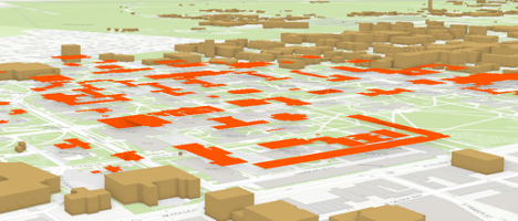 Credit: ChoroPhronesis Lab
Test Your Knowledge
- Uncheck this layer and check back the UP_Roof_Segments.
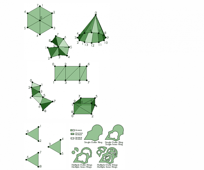
2.2 Sun Shadow Volume Analysis for January 1st
2.2 Sun Shadow Volume Analysis for January 1st
4 ArcGIS Pro [112]
5 ArcGIS Pro [112]
- On the top ribbon, click the Analysis tab and select tools. Search Sun Shadow.
-
Select Sun Shadow Volume (3D Analyst Tools).
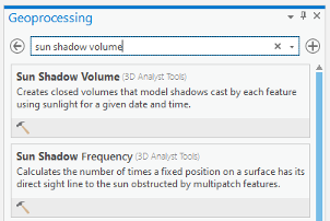 Credit: ArcGIS, 2021
 -
You will use the multipoint feature ‘Building_MP_Campus’ as an input. On January 1st, 2021 the sunrise is at 7:54 am and sunset is 5:52 pm. Set the start and end date as below. Pennsylvania is in the Eastern Standard Time zone. Change the Iteration Interval to 2 and Iteration Unit to Hours. Click Run.
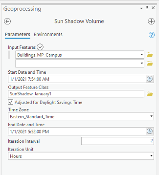 Credit: ArcGIS, 2021
 -
Turn on UP_Roof_Segment and turn off Building_Mp_Campus. Change the color of SunShadow_January to ‘Topaz Sand’. Right-click on the layer, select Properties. Click Elevation and make sure the features are relative to the ground. This is the result of your analysis.
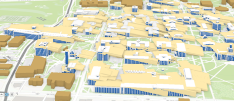 Credit: ChoroPhronesis Lab [41]
 - Open the attribute table and you will see the fields that are attributed. The fields are explained in detail on the ArcGIS Pro website. Here is the explanation for each field:
- SOURCE—Name of the feature class casting the shadow volume.
- SOURCE_ID—Unique ID of the feature casting the shadow volume.
- DATE_TIME—Local date and time used to calculate sun position.
- AZIMUTH—Angle in degrees between true north and the perpendicular projection of the sun's relative position down to the earth's horizon. Values range from 0 to 360.
- VERT_ANGLE—Angle in degrees between the earth's horizon and the sun's relative position where the horizon defines 0 degrees and 90 degrees is directly above.4
- Close the attribute table.
- To make sense of the results of the shadow volumes, you need to symbolize the layer based on the time of day (every 2 hours position of the sun in the local date). On the content pane, click on the symbology under SunShadow_January1.
-
On the top ribbon, under appearance, click Symbology. Select Unique Values.
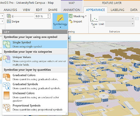 Credit: 2016 ArcGIS
 - On Symbology pane on the right side of ArcGIS Pro, select DATE_TIME as Value field.
-
Select set 3 for the color scheme.
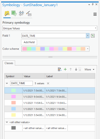 Credit: ArcGIS, 2021
 -
On the content pane or in the symbology pane you can explore the categories.
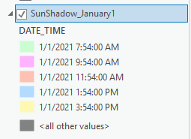 Credit: ArcGIS, 2021
The first category is the shadow created by the sun at 7:54 am and the last one is the shadow created at 3:54 pm. Because of the overlaying layers, you cannot see each shadow clearly.
-
On the top ribbon, click appearance. In Effects Category, define Layer Transparency as 30%.
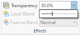 Credit: ArcGIS, 2021
Making a Layer transparent, you can see different shadow volumes easier. However, there are more efficient ways to see your results.
ArcGIS Pro offers a few ways to show an area of interest for your data, including visibility ranges, definition queries, and range. To visualize your data as a dynamic range, you can use any layer, or set of layers, that contain numeric, non-date fields. Once you define the range properties for your layer, an interactive, on-screen slider is used to explore the data through a range you customized’.5
-
On the content pane, right-click on SunShadow_January1 layer and select properties. Click the Range Tab. Setting the range properties of the layer, you can explore the data interactively using a range slider.
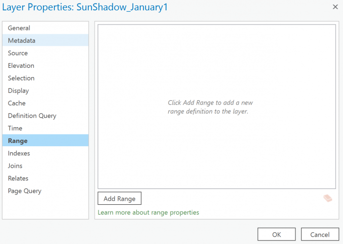 Credit: 2016 ArcGIS
 - To do so, you will choose a field by clicking add range. The range can be set by any numerical field. Therefore, you cannot choose DATE_TIME as a field for range.
-
Click Add Range. Click the drop-down menu of Field. You will see that DATE_TIME is not in the list of fields that can be used because it is not a numerical field. You can select Azimuth. Set the extent from 120 to 236. Click Add. Click OK.
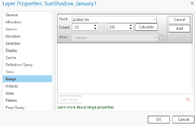 Credit: ArcGIS, 2021
 -
Defining a range, you will be able to use a tool in ArcGIS Pro called Range Slider. This tool gives you the ability to filter overlapping content to make it more accessible and visible. You can see the Slider on the right side of your map.
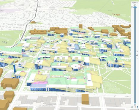 Credit: ChoroPhronesis Lab [41]
 -
To set the Slider, on the top ribbon, under Map, click Range. Under Full Extent choose Sun Shadow_January1. Make sure the min and max are set to 120 and 236.
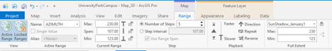 Credit: ArcGIS, 2021
 - Playback defines the speed and direction of the range on the Range Slider to move.
- If you set the current range from 120 to 230. The span becomes 107. Set the number of steps to 5.
-
Make sure the active range is Azimuth, the same field you defined in layer properties.
Check Your Understanding
Take a look at your map. You can see the first visible range now is from 123 to 144. This azimuth range belongs to the first hour of the sunrise from 7:54 am to 9:54 am
Where is the shadow's direction of the first range? (From 7:54 am to 9:54 am)
Click for the answer.North West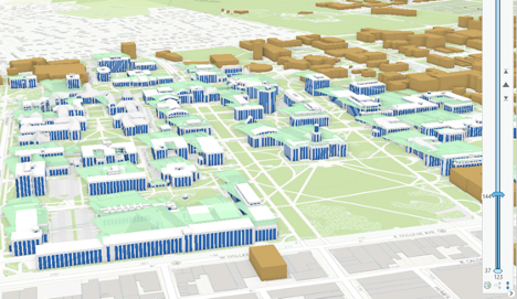 Credit: ChoroPhronesis Lab [41]
 - Click next on your slider and you can see the next result:
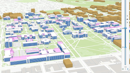 Credit: ChoroPhronesis Lab [41]
This belongs to 8:35 am to 9:54 am. If you continue with the Range slider, you can see all 5 categories of time frames.
-
The last step shows you the changes in shadow volume and its direction towards the end of the day. The shadow moves from North West in the morning to the East towards the end of the day.
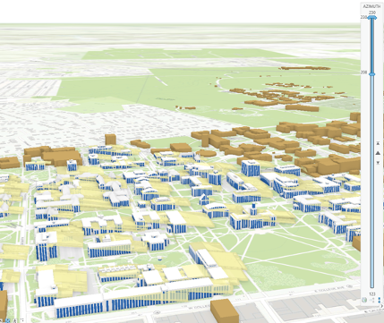 Credit: ChoroPhronesis Lab [41]
 -
Instead of clicking next, you can play the slider and it will play ranges after each other with the pace you have chosen. The pace, from slower to faster can be defined on the top ribbon, Range tab.
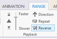 Credit: 2106 ArcGIS
 -
Here is the video of how the shadows of University Park Campus buildings move from sunrise to sunset on 01/01/2021.
Video: Sun Shadow January 1 2021 (00:37) This is video is not narrated. -
You have learned how to change symbology in Lesson 5. To make a more presentable animation of the shadow volumes, define the symbology of ‘SunShadow_January1’ using a gradual color change from lighter colors to darker colors. You need 5 gradual colors; for instance, you can choose a color ramp of Blue or Orange or Green or any other color you find appropriate.
Note: make sure to change the current range from 123 to 230 to see all shadow calcifications under the ‘SunShadow_January1’ layer.
- Make a Screenshot of Campus with gradual symbology of SunShadow_January1. Copy and paste the screenshot into your Word document and label it Task 2.
- Save your Project.
2.3 Calculate Ground Shadow Surface for Walker Building
2.3 Calculate Ground Shadow Surface for Walker Building
In this section, you are going to calculate the ground surface covered by shadow during the day for Walker building.
-
Change the current slider range to 123-230 to see all the shadow volumes.
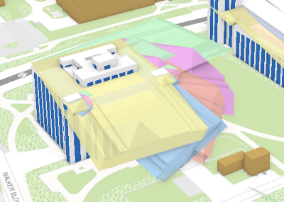 Credit: ChoroPhronesis Lab [113]
 - Zoom to Walker building displayed in the above image.
-
On the Content pane, click List by Selection.
 Credit: ArcGIS , 2021
 - Uncheck all layers. Make sure the only active (checked) layer is SunShadow_January1.
-
Go back to List by Drawing Order.
-
On the top ribbon, under the Map tab, click Select. Draw a rectangle on top of Walker building’s shadows to select them. Make sure not to select other buildings’ shadows.
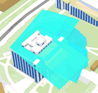 Credit: ChoroPhronesis Lab [113]
 -
Right-click on SunShadow_January1 layer. Click Data, Export Features.
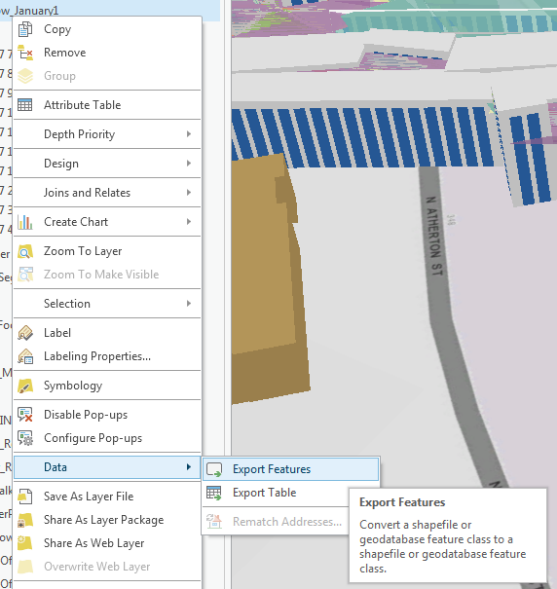 Credit: 2016 ArcGIS
 - The Export Features pane opens. Name the output feature ‘Shadows_Walker’. Click Run.
- On Content Pane, uncheck ‘SunShadow_January1’.
-
Click symbology under Appearance and change the color to the unique value. Change the color from white to another color.
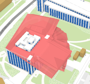 Credit: ChoroPhronesis Lab [113]
 - Now you have the shadow volumes for Walker Building in Multipatch format. To convert it to Polygons, on top ribbon, click Analysis and select Tools in Geoprocessing group.
- Search Multipatch Footprints. Multipatch footprints create two-dimensional polygon footprints. Click the tool.
-
The Input Feature Class is Shadow_Walker. Name the output ‘Shadow_Walker_footprint’. To make one unique surface, you need to group your features based on a unique field. The “Source” field which is ‘Buildings_MP_Campus’ is a unique attribute that can group or dissolve all features together based on it. Click Run.
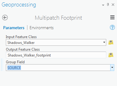 Credit: 2016 ArcGIS
 -
You can see your layer in the 2D Layers list. Uncheck Shadow Walker from the 3D Layers.
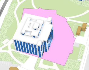 Credit: ChoroPhronesis Lab [113]
Check Your Understanding
What is the shadow area? Do you think it is an accurate shadow area?
Click for answer.The shadow area of Walker building is around 50682.01 square feet. It is not a correct shadow area because at the beginning of this section, we asked you to calculate the ground shadow surface. However, the result of your shadow footprint contains the building itself. Although the building’s roof is covered by shadow during certain times of the day, we are only interested in ground surface.
- To solve this issue, you should subtract Walker building’s footprint from the shadow surface.
-
Turn off Up_Roof_Segment. Drag UP_Buildings from 3D Layers to 2D Layers and turn it on. Make sure it is on top of Shadows_Walker_footprints.
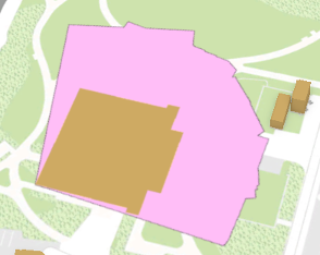 Credit: ChoroPhronesis Lab [113]
 -
On the top ribbon, click Analysis. Select Tools from Geoprocessing group. Search Erase.
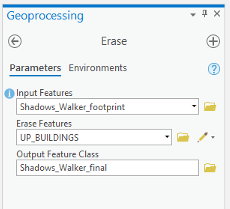 Credit: ArcGIS, 2021
 - Your input Features will be Shadow_Walker_footprints. Erase Features will be Up_Buildings. Name the Output Feature Class ‘Shadows_Walker_final’. Click Run.
- Uncheck Up_Buildings and Shadow_Walker_footprints.
- Now, you will see that the building footprint is extracted from the shadow.
-
Turn on Up_Roof_Segments.
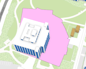 Credit: ChoroPhronesis Lab [113]Check Your Understanding
What is the area of Walker building Shadow now?
Click for the answer.35017.51 Square Feet
- Uncheck Shadows_Walker_final and turn on SunShadow_January1. Clear selection if necessary.
-
In this section, you have learned how to calculate the ground shadow surface for Walker building. In this assignment calculate ground shadow surface for the Nursing Sciences Building.
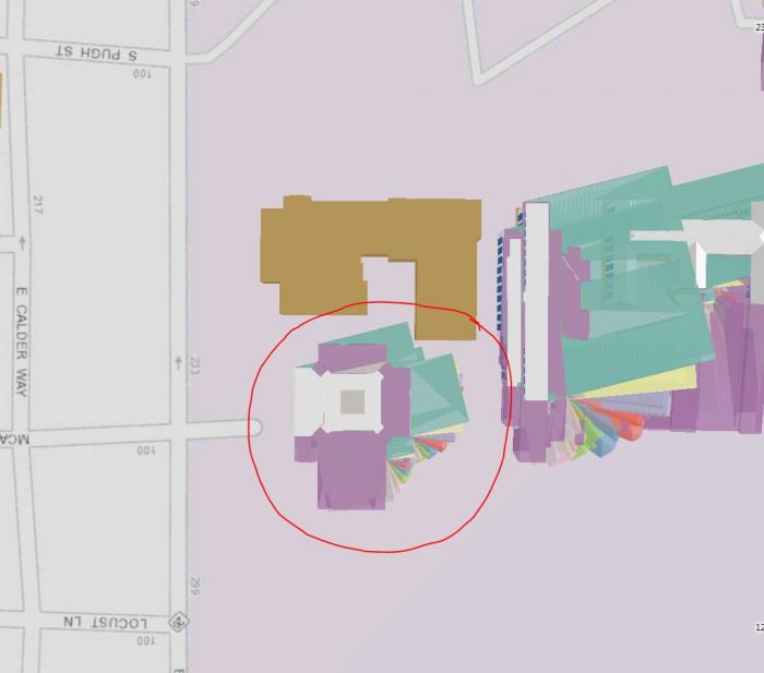 Credit: ChoroPhronesis Lab [113]
 - Make a Screenshot of the ground shadow surface of Nursing Sciences Building. Copy and paste it into your Word document and label it Task 3.
- Make a Screenshot attribute of ground shadow surface of Nursing Sciences Building. We are interested in the total area of shadow surface. Copy and paste it into your Word document and label it Task 4.
- Save the project.
Section Three: Share Your Results on Google Earth
Section Three: Share Your Results on Google Earth
You would like to share the results of shadow volumes over the imagery. One way is to use Google Earth. It has both the imagery and 3D building models and is a good way to present your results.
Step 1: Download and install Google Earth
If you already have Google Earth skip this step. Otherwise, go through the following process:
- Open your web browser. Go to Google Earth [119].
- Click Earth Versions.
- Choose Google Earth Pro on Desktop.
- Click download Google Earth Pro.
- Install Google Earth Pro.
Step 2: Exporting to KML
KML (Keyhole Markup Language) is an XML based file format that is used in Earth browsers such as Google Earth and Google Maps. Consider you would like to share shadow surface in the morning, at noon and before sunset to demonstrate the shaded surface during the day. To do so, you will select the time of the day you are interested in and you will convert the Layer to KML.
- Open UniversityParkCampus_Lesson6_Shadow Project in ArcGIS Pro.
- On the top ribbon, click Select by Attributes.
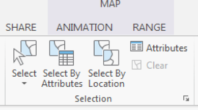 Credit: 2016 ArcGIS [120]
 - A Geoprocessing Pane on the right-hand side of the interface will open. Select SunShadow_January1. Add a clause that DATE_TIME value is equal to 8.36 am. Click Run.
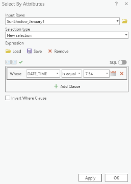 Credit: ArcGIS [120], 2021
 - You can see selected shadow volumes highlighted in blue.
 Credit: ArcGIS [120], 2021
 - On the top ribbon, click Analysis. Select Tools in the Geoprocessing group.
- In the Geoprocessing Pane on the right-hand side of the interface, search KML. Select Layer to KML (Conversion Tools).
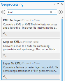 Credit: ArcGIS [120], 2021
 - The input Layer will be SunShadow_January1. Only selected areas will be converted.
- Select the output folder and name the output Shadow_7.54am.
- Option Clamped features to the ground create shadow surface on the ground. Make sure it is checked. Click Run.
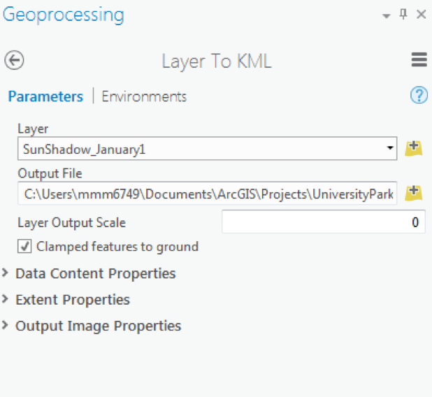 Credit: 2016 ArcGIS [120]
 - This tool creates a KMZ file which might be confusing. We talked about KML and now the result is KMZ. A KMZ is a compressed KML. KMZ is smaller in size and easier to upload to the web. It contains the same data in KML format. You can unzip the file and see the KML inside the KMZ file.
 Credit: ArcGIS [120], 2021
 - Repeat this process for 11:54 am and 3.54 pm shadow volumes.
Step 3: Opening KMl/ KMZ in Google Earth
In this step, you will open three KMZ files you have created in Google Earth. Since Google Earth is free to use, then you can share your Google Earth file with anyone.
- Open Google Earth (Pro).
- Open a file explorer or windows explorer and navigate to the place you saved your KMZ files.
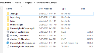 Credit: 2021 Google Earth
 - Move and resize the windows explorer and Google Earth, to see both at the same time next to each other. Drag and drop Shadow_7.54am into Google Earth.
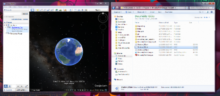 Credit: 2021 Google Earth
 - In the Google Earth interface, you will be directed to University Park Campus and you can see that Shadow_7.54am is added as a layer to Places Pane.
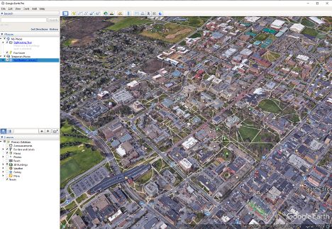 Credit: 2021 Google Earth
 - Right Click on Shadow_7.54am and click properties. Go to the Style, Color tab. Change both Lines and Area to yellow with 60% opacity. Click Ok.
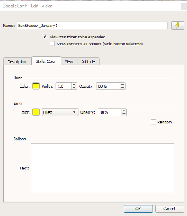 Credit: 2021 Google Earth
 - Use the navigation tool on the up right-hand of the interface to move around and rotate the map.
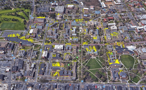 Credit: 2021 Google Earth
 - Drag and drop Layer Shadow_11.54am to Google Earth. Go to the Style, Color tab. Change both Lines and Area to orange with 80% opacity. Click Ok.
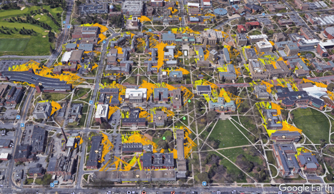 Credit: 2016 Google Earth
 - Drag and drop Layer Shadow_3.54m to Google Earth. Go to the Style, Color tab. Change both Lines and Area to red with 80% opacity. Click Ok.
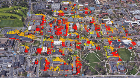 Credit: 2021 Google Earth
 - You can uncheck any of the shadow layers, just to see a shadow surface in a particular time. Zoom in to Old Main and see how the shadow surface changes during the day.
- On the Places Pane, right-click Temporary Places. Click Save Places As. Name the file "UniversityParkCampus_Shadow.kmz" and save it to your desired place. This is a file that you can share with anyone and they can promptly open it on Google Earth.
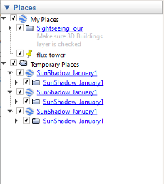 Credit: 2021 Google Earth
Submit your file
Upload "UniversityParkCampus_Shadow.kmz" to Lesson 6 Assignment: Google Earth (2).
Guidelines and Grading Rubric
| Criteria | Full Credit | Half Credit | No Credit |
|---|---|---|---|
| Create a KMZ file | 4 pts | 2 pts | 0 pts |
| The KMZ file has all three shadows | 4 pts | 2 pts | 0 pts |
Tasks and Deliverables
Tasks and Deliverables
Assignment
This assignment has 4 parts, but if you followed the directions as you were working through this lesson, you should already have most of the first part done.
Part 1: Submit Your Deliverables to Lesson 6 Assignment: 3D Spatial Analysis
If you haven't already submitted your deliverable for this part, please do it now. You need to turn in all four of them to receive full credit. You can paste your screenshots into one file, or zip all of the PDFs and upload that. Make sure you label all of your tasks as shown below.
- Task 1: Screenshot of flooded Old Main (End of Section 1).
- Task 2: Screenshot of Campus with gradual symbology of SunShadow_January1 (End of Section 2.2)
- Task 3: Screenshot of ground shadow surface of Nursing Sciences Building (End of Section 2.3)
- Task 4: Screenshot of attributes of ground shadow surface of Nursing Sciences Building (End of Section 2.3)
Grading Rubric Criteria Full Credit No Credit Possible Points Task 1: Screenshot of flooded Old Main 4 pts 0 pts 4 pts Task 2: Screenshot of Campus with gradual symbology of SunShadow_January1 2 pts 0 pts 2 pts Task 3: Screenshot of ground shadow surface of Nursing Sciences Building 2 pts 0 pts 2 pts Task 4: Screenshot of attributes of ground shadow surface of Nursing Sciences Building 2 pts 0 pts 2 pts Total Points: 10
Part 2: Participate in a Discussion
Please reflect on your 3D spatial analysis experience, using ArcGIS Pro; anything you learned or any problems that you faced while doing your assignment as well as anything that you explored on your own and added to your 3D spatial analysis experience.
Instructions
Please use Lesson 6 Discussion (Reflection) to post your response to reflect on the options provided above and reply to at least two of your peer's contributions.
Please remember that active participation is part of your grade for the course.
Due Dates
Your post is due Saturday to give your peers time to comment. All comments are due by Tuesday at 11:59 p.m.
Part 3: Submit Your Deliverable to Lesson 6 Assignment: Google Earth
Instructions
Upload "UniversityParkCampus_Shadow.kmz" to the Lesson 6 Assignment: Google Earth.
Due Dates
Please upload your assignment by Tuesday at 11:59 p.m.
| Criteria | Full Credit | Half Credit | No Credit | Total |
|---|---|---|---|---|
| The KMZ file has all three shadows | 6 pts | 3 pts | 0 pts | 6 pts |
| Total points: 6 pts |
Part 4: Write a Reflection Paper
Instructions
Once you have posted your response to the discussion and read through your peers' comments, write a one-page paper reflecting on what you learned from working through the lesson and from the interactions with your peers in the Discussion.
Due Dates
Please upload your paper by Tuesday at 11:59 p.m.
Submitting Your Deliverables
Please submit your completed paper to the Lesson 6 Assignment: Reflection Paper.
Paper Grading Rubric
| Criteria | Full Credit | Half Credit | No Credit | Possible Points |
|---|---|---|---|---|
| Paper clearly communicates the student's experience developing the 3D spatial analysis in ArcGIS Pro. | 5 pts | 2.5 pts | 0 pts | 5 pts |
| The paper is well thought out, organized, contains evidence that student read and reflected on their peers' comments. | 3 pts | 1 pts | 0 pts | 3 pts |
| The document is grammatically correct, typo-free, and cited where necessary. | 2 pts | 1 pts | 0 pts | 2 pts |
| Total Points: 10 |
Summary and Tasks Reminder
Summary and Tasks Reminder
In this lesson, you have learned the importance of 3D data and 3D maps for spatial analysis. To explore various geoprocessing analysis, you have practiced two different methods to analyze flood and sun shadow analysis. In terms of 3D data, it is important to remember the difference between multipatch as 3D data and extruded 2D data. In the end, you experienced how to share your work on other platforms.
Reminder - Complete all of the Lesson 6 tasks!
You have reached the end of Lesson 6! Double-check the to-do list on the Lesson 6 Overview page to make sure you have completed all of the activities listed there before you begin Lesson 7.
Lesson 7: Unity I
Overview
Overview
In this and the next two lessons, you will be working with the Unity3D game engine, simply referred to as Unity throughout the rest of the course. Unity is a rather complex software system for building 3D (as well as 2D) computer games, and other 3D applications. Hence, we will only be able to scratch the surface of all the things that can be done with Unity in this course. Nevertheless, you will learn quite a few useful skills related to constructing 3D and VR applications in Unity dealing with virtual environments. Furthermore, you will become familiarized with C# programming (the main programming language used in this engine) through a series of exercises that guide you on developing your first interactive experience in a game engine.
This lesson will begin with an overview to acquaint you with the most important concepts and the interface of Unity. It will cover basic project management in Unity, the Project Editor interface, manipulation of a 3D scene, importing 3D models and other assets, and building a stand-alone Windows application from a Unity project. Moreover, you will learn how to create a very simple “roll-the-ball” 3D game using C#, which will prepare you for more advanced interaction mechanics we will be implementing in the next lessons.
Learning Outcomes
By the end of this lesson, you should be able to:
- Explain the role of interaction for 3D/VR projects and the role of game engines for enabling access to 3D models
- Create 3D projects in Unity3D, import 3D models, and understand the basic concepts and interface elements of the Unity editor
- Manipulate scenes and add script components to game objects
- Import custom Unity packages into a unity project
- Develop a basic understanding of the physics engine of Unity (e.g. gravity, collision detection)
- Run projects inside Unity and build stand-alone applications from them
- Have a basic understanding of how to make an experience come “alive” by programming behaviours for game objects
Lesson Roadmap
| To Read |
|
|---|---|
| To Do |
|
Questions?
If you have any questions, please post them to our "General and Technical Questions" discussion (not e-mail). I will check that discussion forum daily to respond. While you are there, feel free to post your own responses if you, too, are able to help out a classmate.
The Unity3D Game Engine
The Unity3D Game Engine
Unity is a game engine developed by Unity Technologies. Development started over a decade ago and the initial version of Unity was released in 2005. Unity has experienced rapid growth, in particular over the last few years, and is undoubtedly the most popular game engine out there. According to the Unity website, 50% of mobiles games, and 60% of AR/VR content are made with unity. The company has over 2000 employees and more than 3 billion devices worldwide are running unity [1]. There have been several major releases of Unity over the years with new minor versions being released on a regular basis. The current major release is Unity 2019 with the latest stable version being version 2019.1.10 at the time of this writing. In 2010, Unity Technologies launched the Unity Asset Store, an online marketplace where developers can obtain and sell assets for their Unity projects including tools and extensions, scripts, artwork, audio resource, etc. (Unity Asset Store [121]). Today there exists many side products and activities around the Unity platform. For instance, Unity offers its own Certification Program (Unity Certification [122]) to interested individuals and has its own VR/AR division called Unity Labs (Unity Labs [123]).
One of Unity’s main advantages is that it is cross-platform both during development time and deployment. Unity applications can be deployed for many platforms including Windows, macOS, Linux, and different mobile operating systems. That means not only can you choose on which operating system you want to create your 3D application but once it has been created, it can be deployed to a large variety of devices. For instance, you can build stand-alone programs for the common desktop PC operating systems (Windows, macOS, Linux, etc.) as well as versions for different mobile phones (e.g., Android-based phones and iPhones). Of course, the differences in performance and hardware resources between a PC and a mobile phone need to be considered, but there is support for this in Unity as well. In addition, Unity has been a front-runner when it comes to building VR applications and supports or provides extensions for a large variety of consumer-level VR devices such as the Google Cardboard, Gear VR, Oculus Rift, HTC Vive, and other mainstream HMDs. Three of the most popular VR development plugins (a series of libraries and pre-made game objects that facilitate access to HDMs and enable developers to program different functionalities) for unity are SteamVR (by Valve corporation), OVR (also known as Oculus integration, by Oculus), and VRTK (a community-based plugin by Sysdia solutions).
While its origin is in the gaming and entertainment industry, Unity is being used to develop interactive 3D software in many other application areas including:
- simulation (Universe Sandbox [124]);
- educational/training simulations (Surgical Anatomy of the liver demo [125]);
- design, architecture, and planning;
- virtual cities and tours;
- data visualization (NOAA [126]);
- history and cultural heritage;
- cognitive science research;
- and last but not least geography and GIS.
More examples can be found at Made with Unity [127]
In this course, we will use Unity to build simple interactive and non-interactive demos around the 3D environmental models we learned to create in the previous lessons. You will also learn how to produce 360° videos from these demos such that these can be watched in 3D using the Google Cardboard. Lastly, you will learn how easy it can be to add physics to different geometrical objects in unity and make them “behave” the way you want.
Assignment (Unity 3D/VR Application Review)
Search the web for a 3D (or VR) application/project that has been built with the help of Unity. The only restriction is that it is not one of the projects linked in the list above and not a computer game. Then write a 1-page review describing the application/project itself and what you could figure out how Unity has been used in the project. Reflect on the reasons why the developers have chosen Unity for their project. Make sure you include a link to the project's web page in your report.
Grading Rubric
| Criteria | Full Credit | Half Credit | No Credit | Possible Points |
|---|---|---|---|---|
| URL is provided, the application/project uses Unity, is not already listed on this page, and is not a game. | 2 pts | 1 pts | 0 pts | 2 |
| The report clearly describes the purpose of the application/project and the application itself. | 3 pts | 1.5 pts | 0 pts | 3 |
| The report contains thoughtful reflections on the reasons why Unity has been chosen by the developers. | 3 pts | 1.5 pts | 0 pts | 3 |
| The report is of the correct length, grammatically correct, typo-free, and cited where necessary. | 2 pts | 1 pts | 0 pts | 2 |
|
Total Points: 10 |
References
[1] Unity [128] (accessed on July 16, 2019)
Downloading and Installing Unity
Downloading and Installing Unity
Before providing an overview of Unity’s main concepts and interface, let us start by downloading and installing Unity so that you can follow along and immediately start to experiment with the things you will learn about. Unity comes in three different versions: the “Personal” is completely free, while the “Professional” comes at a monthly fee ($125 at the time of this writing), and the “Plus” at a monthly fee (25$ at the time of this writing). For our purposes, the Personal Edition is completely sufficient. If you are interested in knowing more about the differences between the versions, an overview is provided at unity Store [129].
Please follow the instructions below to download and install the Personal Edition of Unity:
-
Go to Download Unity [130] and click on “Download Unity Hub“. The Hub is a new mechanism for managing the different versions of the Unity editor you want to install on your machine.
-
Execute the downloaded file (UnityHubSetup.exe) and go through the installation dialog. Once the installation is finished, if you have checked the “Run Unity Hub” option at the end of the installation process, when you click on Finish, the Unity Hub will open. Alternatively, you can also navigate to your desktop and double click on the newly created Unity icon named “Unity Hub” to start it.
-
You should be able to see a window as depicted below. Locate the profile icon on the top right corner of this window, click on it, and then select “Sign in”. A new window will pop up asking for your login information. Sign in with your unity account. If you do not have a unity account, go ahead and create one using the “create one” link on the pop-up window, and then sign in.
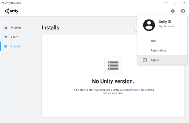 Credit: Unity [131]
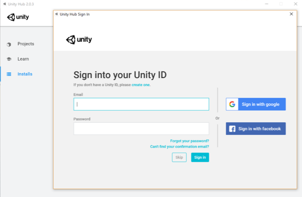 Credit: Unity [131]
 -
Once you are signed in, make sure the “Installs” category is selected on the left panel (the one highlighted with the red area in the figure below) and click on the blue “Add” button. A new window with pop up where you can select which version of unity you want to install. At the time of writing this, the latest stable version is 2019.1.10f1. Please download this version as it is compatible with the rest of the instructions given in the course (if you choose to install a new version of the editor, you might need to change some of the c# codes we will be using). To do so either click on the "Download archive" on the window that has poped up, or follow this link (https://unity3d.com/get-unity/download/archive [132]). This action will open a new tab in your default web browser. On that web page, select the Unity 2019.X, navigate to almost the end of the page and then click on the green button next to "Unity 2019.1.1" that says "Unity Hub". This will open this version of Unity editor in the Unity Hub for you to download and install.
This action will automatically proceed to the next dialog window in the Unity Hub, where you can select which extra modules to install. If you do not have Microsoft Visual Studio, it will be automatically selected for you on this list. Moreover, if you are developing on Linux or Mac, make sure to select the relevant “Build” module for your OS, so can deploy your virtual experience as a desktop application later. Click “Next” and wait until the installation is finished (This could be a lengthy process, so be patient).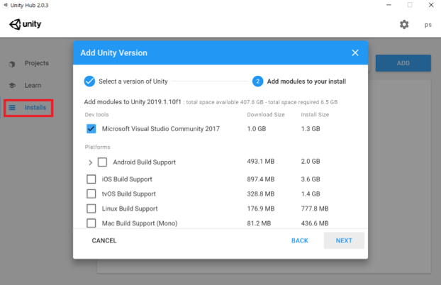 Credit: Unity [131]
 -
Once the installation is complete, you should have a Unity icon (with a specific version) on your Desktop and “Unity” in your Start Menu. Before Starting Unity, we need to create a project. To do this, make sure the “Projects” category is selected in the Unity Hub (the one highlighted with the red area in the figure below) and click on the blue “New button”. Unity provides several templates for us to choose from (depending on the purpose of the project, e.g. 2D, 3D, VR lightweight RP, etc.). For the purpose of this lesson, we will use the default 3D template. Change the name of your project to “MyFirstUnityProject”. You can also change the location where the project will be saved to another address if you want (this is optional and solely based on your preference). Press “Create”, and after a few minutes the unity editor will be ready for us to use.
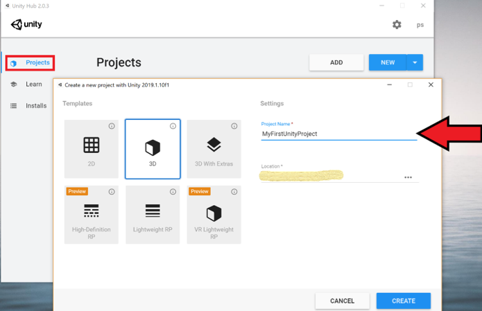 Credit: Unity [131]
Unity Interface and Basic Unity Concepts
Introduction
Unity Interface and Basic Unity Concepts
Introduction
A Unity project consists of one or more Scenes and each Scene is formed by a set of GameObjects located in the Scene. The name GameObject obviously is based in Unity’s main purpose as a game engine but these entities can be anything that we would want in a 3D application: 3D models of buildings, terrain, lighting sources, cameras, avatars, etc. They can also be non-physical things, in particular, abstract entities just serving as containers for scripts that perform some function such as realizing changes in the environment when the 3D application is executed. The main programming language used to write scripts in Unity is C#.
When editing a project in Unity as well as when executing a Unity project, only one Scene is active at any given moment. Each Scene has a name and you can see the name of the currently active Scene in the title bar: There are four parts separated by hyphens, the version of Unity, the name of the Scene, the name of the project, and the platform currently chosen to build the Unity project for. The Scene name part right now will be “SampleScene” as this is a default scene automatically create by Unity whenever a new project is created.
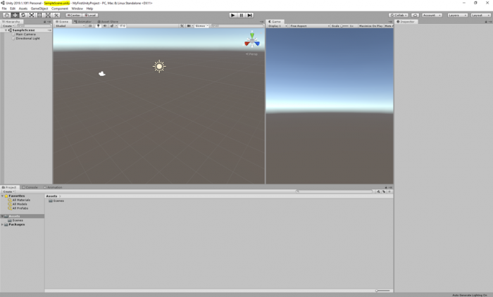
In a computer game built in Unity, each level would be a different Scene. In addition, things like cut scenes and menu screens would also be realized as individual Scenes. The game code will then have to implement the logic for switching between the Scenes. Similarly, in a non-game 3D application, you could also have several Scenes to switch between different environments, e.g. an outdoor model and several indoor models.
To give you an example of having more than one scene in a project, as well as how a scene can be populated with gameobjects, we have prepared for you a unity package that contains a scene called “Main”, populated with terrain, and a few classic buildings of the PSU campus in State College. Download this Unity Package [104]. Once the download is complete, simply double click on it, and an import window inside the Unity editor will pop up showing the folder structure inside the package. By default, all the folders should be selected. Click on import, and all the selected folders will be added to the “Assets” structure of your project. If you receive a warning saying that the package was exported using an earlier version of unity, simply click on "Continue".
This is a relatively large package (almost 200MB), and therefore it could take a while before the import is complete.
Once the import is finished, you may notice that a new folder called “Historic Campus” is added to your project folder structure under Assets (highlighted in the figure below). In addition, another folder with the title “Standard Assets” is also added, which is a collection of ready-to-use assets provided by Unity to speed up development time. The standard assets folder contains a “first-person controller” prefab that is used in the historical campus scene.
This folder structure is used to organize the resources of your project. It is good practice to organize your files into folders based on some meaningful structure and add a sensible title to the folders.
If you select the “Historic Campus” folder with your mouse, you can see that its contents are listed on the down-center part of the project panel in the editor. This is another way to view and navigate your project folder structure. There are several subfolders inside the Historic Campus folder that contain the 3D models, textures, and other resources used in the scene. To open the imported scene of the historical campus, simply double-click on the “main” scene. We will this scene to go over the basics of unity.
If you click on the small “Play” button on the top center of the editor (alternatively you can use the “Ctrl + P” shortcut), you can run the scene and see it in action. Currently, the scene has three buildings, a simple flat plane, and a first-person controller. Use your mouse to look around, and the WASD keys to navigate the environment. Once you are done experimenting, you can stop the scene from running by either clicking on the play button again or pressing “Ctrl + P”.
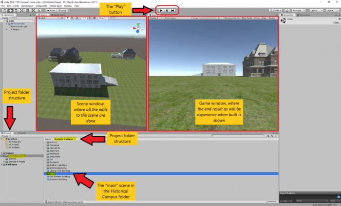
Overview on Main Windows in the Project Editor
Overview on Main Windows in the Project Editor
As you may have already noticed in the previous section, there are two main windows in the editor that show two different views of the scene. The window you will mostly look at when creating a Unity project is the Scene Window currently open in the left-center of the screen. It shows a 3D view of the Scene you are currently working on, in this case consisting of a few historic PSU campus buildings from the year 1922 and an underlying plane. The window on the right-center of the screen is called the game window and shows the output of the scene when the project is built. The game window allows you to have a feeling of how this scene of your virtual experience will look like from a user’s perspective, while you are developing. Evident from its title, and as you have already experienced, once you “play” your scene you experience it in this window.
You can alter the arrangement of all the panels and windows to your liking by simply dragging them around. For instance, if you prefer not to see the game window while you are editing your scene, you can drag its panel header and drag it next to the scene window and then drop it.
Video: Unity - Moving windows around (00:12) This video is not narrated.
If you click into the scene window to give it focus, you can then use the mouse to change the perspective from which you are looking at the scene. The details of how this goes are affected by a set of buttons at the top left. The seven buttons on the left are the main ones to control the interaction with the scene and the objects in it with the mouse. For now, make sure that the first button (i.e. Hand tool) is selected as in the screenshot below:

Now go ahead and try:
- Use the mouse wheel to zoom in and out
- Move the mouse with the left button pressed to pan
- Move the mouse with the right button pressed to look around
You will learn more details about how to interact with the Scene Window soon. Let us now turn our attention to the panel on the left, which is the Hierarchy panel. It lists the GameObjects in the Scene. Currently, these are the “FPS Controller”, a “Directional Light” and the “Campus” 3D model. The panel is called “Hierarchy” because GameObjects are organized in a hierarchy and the panel shows us the parent-child relationships. The “Campus” object is actually just a container for grouping the 3D objects of the individual buildings, and of the terrain together. By clicking on the small arrow on the left, you can expand that part of the hierarchy and will see the sub-entities of the “Campus” object, called “Terrain”, and “Buildings”. As you probably already noticed, these objects, in turn, are just containers. “Buildings” for instance contains the models of the individual buildings shown in the Scene.
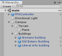
You can double-click on any entity in the hierarchy to change the view in the Scene Window to focus on that particular object. Try this out by double-clicking on some of the buildings, e.g. starting with the “Woman’s building” object.
You may already have noticed that selecting an object in the Hierarchy Window, either by double-clicking it or by just doing a single click if you don’t want the view in the Scene Window to change, has an effect on what is displayed in the window on the right side of the Scene view. This is the Inspector Window, which has the purpose of displaying detailed information about the selected object(s) in our Scene as well as allowing us to modify the displayed properties and add new components to a GameObject that affect its appearance and behavior. If you select the “Liberal Arts” building and check out the Inspector Window you will see that there is a bunch of information grouped into sections, including so-called components attached to the object that will determine how the object will be rendered in the scene. Now compare this to what you see when you select the “FPS Controller” object or the “Directional Light”. Since these are special objects with particular purposes other than being displayed in the Scene, they have special properties related to that particular purpose, for instance, the FPS controller has a child called “FirstPersonCharacter”. This gameobject has a camera component attached to it (as the camera should move when the player character moves around the scene) with multiple parameters (e.g. Filed of view). As an experiment, change the value of the field of view parameter using the slider to see its effect.
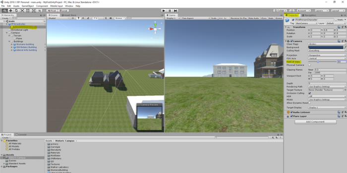
The “Directional Light” is one of several possible light sources that Unity provides. It essentially simulates the sunlight and will be used to render the Scene, resulting in shadows, etc. Instead of having a camera component attached to a child of the FPS controller object, we could have added a static “Main Camera” to the scene. The camera object determines what will be shown when the Unity project is being run, either inside the Unity editor or after we exported it as a stand-alone application. To see the difference, disable the FPS controller and add a main camera to the scene as shown in the video:
Video: Unity - Adding a camera and moving it around (01:06) This video is not narrated.
We first need to disable the FPS Controller by unchecking it in the inspector panel. Then, we need to add a static camera to our scene. To do this, we will click on the GameObject menu on top of the editor and select camera. Next, we need to adjust the rotation and position of our static camera so it captures the part of the scene we want to show. To do this, we will use the menu we have addressed previously to switch our mouse functionalities. In the video, you have seen the use of the Move and Rotate tool. Note that the same results could be achieved by manipulating the numerical transform values of the camera GameObject in the inspector menu. To try this, observe the numerical values while you use the mouse to move or rotate the object, or alternately, change the numerical values to see their effect.
A very handy way to change the camera perspective (and also the position and orientation of other GameObjects) is by first changing the Scene view to the desired perspective and then telling Unity to use that same perspective for the camera object. This can be accomplished by using "GameObject -> Align With View" from the Gameobject menu bar, or by simply using the keyboard shortcut CTRL+SHIFT+F. To practice this, double-click the Old Botany building to have Scene view focus on this building. Now select the Camera object (single click!) and use Align With View. See how the camera perspective in the Camera Preview has changed to be identical with what you have in the Scene view? On a side note, the GameObject menu also has the function “Align View to Selected” which is the inverse direction of “Align With View”: it can, for instance, be used to change the Scene view to your current camera perspective.
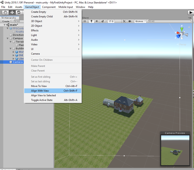
The last panel we will cover in this section is the “Console”. This panel displays warning and error message when Unity experiences any problems with your project or prints messages that you log in your source code (e.g. for debugging purposes).
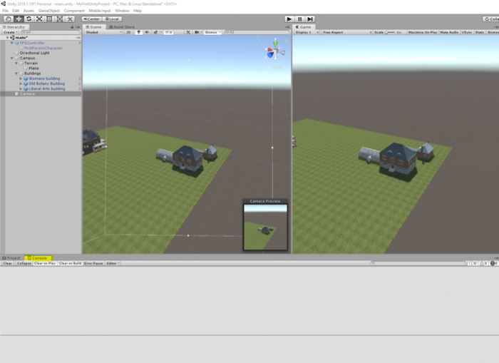
As was previously mentioned, the way the individual windows and panels are arranged here is the default layout of the Unity editor. But you can freely re-arrange the windows in pretty much any way you want, for instance by clicking on the project tab and dragging it to a different part of the screen. The Layout drop-down menu at the top right allows you to switch between predefined layouts as well as define your own layouts. If somehow the layout got messed up, you can select "Default" there and it should go back to the standard layout that we have been using here so far.
By now, you should be able to move and rotate GameObjects in the scene and play and stop the scene. With respect to the latter, there is an important and useful functionality to know about the Play Mode: While in Play Mode (either running or paused), you can still make changes to the objects in your scene, e.g. by changing parameters in the Inspector panel. However, in contrast to changes you make in Edit Mode, these changes will only be temporary; they will not be saved in your Scene. So when you stop play and go back to Edit Mode, these changes will be gone. This can still be very useful because it allows you to try out things while the project is running and immediately see the impacts.
Building a Project
Building a Project
The last thing we want to quickly mention here is how you actually build a stand-alone application from your Unity project, so basically how to create a stand-alone program for a platform of your choice that does the same thing that you get in the Unity editor when in Play Mode. This is done by going "File -> Build Settings…", which opens a new dialog:
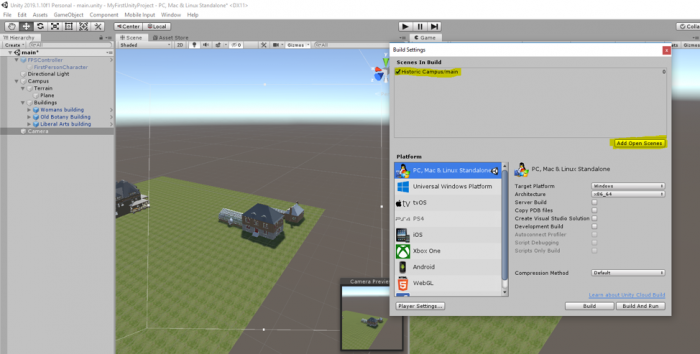
In the pane at the top, you can select the Scenes that should be included in the build. Click on the “Add Open Scenes” button to add the current scene to the build window. At the bottom left, you select the target platform for your build. It is possible to install extensions to build applications for other platforms than you currently see here. The one relevant for this course is “PC, Mac & Linux Standalone” and you then have to select “Windows” as the Target Platform on the right. With the “Player Settings” button at the bottom, you can set more parameters that affect your build. Pressing “Build” will start the process of compiling the stand-alone application, while “Build & Run” will in addition run the program after the compilation process has finished. When you have all parameters for your build already set, you can use “Build & Run” directly from the File menu. When you click "Build" you will be asked to choose a folder to save the project in. In the following save dialog, navigate to your “Documents” folder and use “Walkthrough” as the file name under which the application will be saved. Then click “Save”. Unity will show you the progress bar for building the application which can take a few minutes. If you have a Mac, the windows application would not be played on your computer. You need to create a Mac application.
Getting More Familiar with the Editor
Getting More Familiar with the Editor
It is time to get more familiar with the interface and components of the Unity Project Editor and get some practical experience. The Unity web page [134] provides video tutorials on the basics and some advanced aspects of the Project Editor that we are going to rely on here. So please grab a cup of coffee, tea, or whatever you prefer, and watch the videos listed below. Please pause often to try out and practice the things explained there on the project you have. In particular, make sure to practice changing the view by panning and zooming, as well as quickly changing the perspective with the View Gizmo and manipulating objects in the Scene view. If something goes completely wrong, you can always delete all the folders and re-import the unity package and then start over.
Video: Interface Overview (2:17 min)
Navigating the Unity editor interface is easy. The core of the interface consists of five main panels. The Scene View, the Hierarchy, the Game View, the Project panel and the Inspector panel. The Scene View is where you'll visually construct your game, manipulating objects in 2D and 3D. The Game View is where you will preview your game, and this becomes active when you hit the play button, allowing you to playtest at any time inside the editor. The Hierarchy lists all objects in the scene in alphabetical order and in hierarchical order in order to show parenting, a way of grouping objects. The Project panel shows all assets that you are currently working with, in one place, giving you quick access to everything you are building your game with from scripts to textures, 3D models, video, and audio. The Inspector is a context-sensitive panel that shows the properties of whatever object, asset or setting panel you've selected. Click on something new and the Inspector immediately switches to show properties of that thing. The play controls allow you to playtest the game, pause, and progress frame by frame for more detailed testing. The tools in the top left allow you to navigate the Scene View and also manipulate objects visually. There are also toggles to allow for switching between local and world space and center or pivot point based rotation. The Layers dropdown allows you to quickly show and hide layers of content in your game. The Layout dropdown allows you to switch between differing layouts of the Unity interface. In the top right of the interface are the layers and layout dropdowns. This concludes the interface overview. Continue to watch tutorials to learn more about each individual panel. Subtitles by the Amara.org community
Video: The Scene View (4:20 min)
The Scene view is where you will visually construct your game. And this can be navigated by making use of the buttons above the view. These buttons correspond to the Q, W, E and R buttons on the keyboard. The first button, the Hand Tool, is purely for navigating. With this tool selected drag with the left mouse button to pan, and with the right mouse button to look around First Person style. Hold the Alt key with this tool and left mouse button drag will let you orbit around the point you were looking at. Whilst Alt and right mouse button dragging will zoom the view. With any object selected in the hierarchy, you can focus on the object either by double-clicking the object's name or by pressing F with the mouse cursor over the Scene view. The remaining three buttons allow you to adjust position, rotation, and scale of objects. By dragging the corresponding axis handles you can move objects in X, Y or Z. Likewise, this also applies to moving in 3D by dragging from the center, although this is not necessarily recommended for moving in 3D space. Likewise for rotating you can rotate in all three axes, or you can just drag from within those, but again a lack of control will occur when trying to drag in all three axes at once. And again with scaling you can scale objects in all three individual axes or drag from the center point in order to scale uniformly. In this instance, it is recommended to drag from the center in order to keep scale properties in proportion. In the main bar of the Scene view, you will see two drop-down menus that handle how the Scene view is rendered. You can switch to wireframe or look at alpha of how your objects are displayed for example. These are followed by three toggles. The first toggle toggles lighting in the scene The second - whether a skybox is rendered or not. And the third allows you to preview audio from the game from wherever the editor camera is currently located. The editor camera simply refers to the camera that you are looking at the Scene view from. It is not a camera object in your scene. So for example, if I were to move my camera very far away from the sound source and preview the audio again. You can hear that it's quieter than it was before. To the right of the panel are the Gizmo menu and search box. The Gizmo menu lets you adjust gizmos, the 2D icon shown in the Scene view to help you identify components in the scene. Such as lights, audio sources or cameras. These can be adjusted by size and also be toggled between 2D and 3D. The search field lets you search for a particular object by searching for its name. And this highlights the object by fading out other objects in your scene. Again, if you are not focused on the actual object that you've found by searching then you can simply use the Focus feature to find it. This search also singles out the object in the Hierarchy so by then selecting the object you were looking for and pressing F to focus, or double-clicking - you will then be taken to that object. The final part of the Scene view you should understand is the View Gizmo itself. This allows you to switch from Perspective 3D view to Orthographic cameras from sides, top and bottom. When dragging to orbit your view in Orthographic view you will be switching to Isometric view. You will be notified of this by the term ISO written underneath the View Gizmo but do not confuse this with actual 3D Perspective view and be aware that you can switch back to Perspective view simply by clicking on the white cube in the center of the View Gizmo.
Video: The Game View (3:11 min)
The Game View in Unity is invoked when the Play button is pressed. In this, you can playtest your game and get an idea of what the gameplay will be like when it's built. This can be paused and stepped forward at any time in order to give you more accurate testing. You can also tweak things whilst you are in play mode in order to see what the gameplay is like with different settings. The game view also allows you to set resolution specific to the target platform that you're using. For example, my game view is set to Standalone with a resolution of 1280 by 720. If I choose to then maximize on play the game view will restrict to exactly that resolution so that I can see what it will look like. To adjust this I go to Edit - Project Settings - Player and this shows me the default screen width and height under resolution. If I edit this I will see the change made immediately in the game view. And if I choose to switch to a different target platform I will get the resolution for that setting. For example, if I switch to Web Player and return Web Player is then featured as the target platform I'm building for and the preview mode for the game view. In addition, to Maximise On Play, the game view also has a Stats button to allow you to see performance statistics based on your game and also the ability to show Gizmos in the same way that the Scene view shows them already. As you can adjust things whilst in play mode you should also be aware that any changes that you make will be undone when returning to your project. This is specific to changes that are based on game objects in your scene and not game objects that reference assets in the project. For example, if I was to change something relating to a material that change is made to the original asset. Whereas if I was to change something on a specific component that change will be undone when play is pressed again. It's also worth being aware that when you press play, your game is running and you can hint this by going to Unity - Preferences on Mac or Edit - Preferences on PC. You can choose under Colours a play mode tint, I've chosen a shade of blue, but I can make this any colour that I need to. That way, when you press play the rest of the interface will change to this colour. This is to remind you that you are in play mode and will lose changes if you continue to work in that mode.
Video: The Hierarchy and Parent-Child Relationships (3:48 min)
The Hierarchy in Unity is a complete list of any object in your open scene. Objects are listed from A to Z order, but it is also possible to create hierarchies of objects which are in turn listed in A to Z order. Hierarchies of objects mean that they are grouped, with the topmost object being called the Parent Object and the rest being referred to as Children or Child objects. These objects then have their transform values based upon that of their parent object. For example, the position of an object when loose in the hierarchy is based on its distance from the world origin or zero point. But when this object is made a child of another object it's position is relative to that of its parent. In this example, the character object is at the origin of the 3D scene, the position (0, 0, 0). And there is a cube object at position (5, 1, 5). But when the character object is made a child of the cube - its origin, or zero point, is then the position of the parent object, the cube. Now the character's position is said to be (-5, -1, -5). This being the distance from the cube object, it's parent and therefore it's origin position. We can also see that with Pivot Point Rotation enabled the rotation is now based on the parent object rather than rotating around its own axis. The same then applies to movement and scaling. And this will apply until that object is no longer a child. Other features of the hierarchy are the Create button and Search field. The create button on the hierarchy acts as a mirror of the Game Object - Create Other top menu and this will allow you to create various different things that you will need to construct your games in Unity. Whilst the search field works in a similar way to the search field in the Scene view, allowing you to narrow down objects using their name. The scene view then reacts by greying out other objects allowing you to see the object you've searched for more easily. You can also make use of the modifier T: in order to search for types of object. Type here being considered as one of the objects components. For example, if I search for T:Light there is only one light in my current scene, one on the end of the players gun. And if I search for T: Audio Source I'll be narrowed down to 3 objects, the only ones in the scene that happen to have audio source components attached to them. When searching in this way, the bottom of the hierarchy shows the path to the object that you've found. Damage audio source being the one I have selected, Player being its parent and Cube being the parent of that object. This means that when canceling the search you can easily see where your object is. It will also remain selected and the parent objects of that object will be expanded to show where it's located.
Video: The Project Panel and Importing (2:34 min)
The Project Panel is where you store all of the assets that make up your game. Anything you create with the panel, and any asset you import, will be kept here. You can create Unity-specific assets by clicking the create button at the top. Or import assets created in an external application. You can import by right-clicking, by using the top menu or simply by adding files to the assets folder in your operating system or by saving from another application. The project panel is a mirror of your assets folder. And when viewing the assets folder in your operating system you'll notice that meta files are created for every asset that's placed into the project. Note that once the asset is in you should always use the project panel to move it around or edit it rather than using your operating system as this can break lines in the library of your project. The project panel has two styles of view, one and two-column. These can be switched by clicking the context menu button in the top right. One column view lets you see assets in a simple hierarchy as shown here. Two-column view gives you more flexibility and more options to work with assets. You can select, move and duplicate assets in the project. Create and organize into folders. As well as label assets and search for them. Assets can also be previewed in a thumbnail form by dragging the slider at the bottom, with hierarchies then being shown with a right-arrow that can be used to expand or collapse them. Assets can also be searched for and sorted by their name, their type, a label or by a favourite grouping. To create favourites you could perform a search and then click the star button in the top right and give your new group a name. You can even search the assets store from the project browser. By typing in the standard search field and switching from assets to asset store.
Video: The Inspector (4:19 min)
The Inspector panel in Unity is a panel for adjusting settings for any object, asset, and editor preference. For objects, the inspector begins with a title, a checkbox for you to check if the state of the object will remain static in the game. This means it's a valid candidate for light-mapping and navigation mesh baking. And then the tag and layer drop-downs. Tags allow you to assign a tag to one or many objects in order to address them via code. Whilst layers allow you to group objects and apply certain rules to these layers such as lighting or collision rules. After these elements, the inspector then lists the components attached to an object. Beginning with the transform, the default position, rotation and scale of your object. On any component the inspector allows you to adjust fields in various ways. You can drag over the values, you can click and retype, or you can choose to reset the values using the cog icon to the right of the component. In addition to the cog, there is also a link to the reference material on the component and you can get to this by clicking the blue book icon, and this will open the documentation page on this component. A context-sensitive panel, the inspector changes to whatever you have selected, meaning that you can adjust any object and immediately dive into settings and back. Because Unity makes use of dragging and dropping to assign values sometimes you may click on items that take you to their settings, rather than the one you wish to apply them to. And for this reason, you can lock the inspector in order to work with a particular item and then unlock once you are done assigning settings. For example, on this game object, I have a script component to which I must assign an array of textures. But when I select my first texture I want the inspector to remain on my game object, rather than showing the texture's settings. I could simply hold down the mouse or I can simply select the object and click on the lock at the top of the inspector. This way when I select one or many textures I can then drag and drop without the inspector changing focus. Once I am done with this, I simply click the lock again and I can then select anything that I need to. The inspector also offers a way of finding assets used on objects. For example materials. When clicking on an asset used within a renderer you can see that asset highlighted inside the project panel. It does this by highlighting with a yellow outline. This helps you easily find the assets that your game objects depend upon. In this example, we can see an object that has a material assigned to its renderer. This particular material is then previewed at the bottom of the inspector and I can adjust that material directly from here. However, the other two objects that I don't have selected also use this material, so I must bear in mind that the actual material I am adjusting is the original material asset inside the project and not a particular instance of an object in the same way that I can adjust the scale of this object without adjusting any other objects that also have a scale value. Components within the inspector can also be disabled by clicking the checkbox to the left of their name. And the entire object can be disabled by clicking the checkbox next to its name at the top of the inspector. When objects are disabled in this way you'll notice that their name is greyed out inside the hierarchy panel. And that's the basics of the inspector in Unity.
Video: Build and Player Settings (1:50 min)
The Build Settings can be accessed from the File menu by going to File - Build Settings. A build, in development, is a term used to describe an exported executable form of your project. And given Unity's multiplatform nature this varies for each platform. For web players, Unity will export an HTML file with example embedding code and a .Unity 3D file which contains your game and will be run by the Unity web player plug-in in your browser. For standalone Unity will export an executable version of your game for PC, Mac, and Linux. For iOS Unity exports an Xcode project that can be opened in Apple's Xcode SDK and run on the device for testing and submission to the app store. For Android Unity exports an APK file that can be opened in the Android SDK. Flash exports an SWF file associated assets, and yet again an HTML file with example embedding code. Google Native Client exports a Google Chrome browser compatible web player game. And for consoles Unity builds directly to your hardware development kit. The build settings work with Unity's player settings to define settings for the build that you create. Split into cross-platform and per-platform you can set some basic values at the top and then choose settings below that are specific for the platform you are developing for. One thing to note as a beginner is that the resolution in the Resolution and Presentation area is the setting you can select for the game view. For details of other per-platform settings refer to the manual link below.
Video: Game Objects and Components (2:12 min)
Game Objects are the items that make up your Unity scenes Everything within a scene is considered a game object and these objects are made up of a number of components. Each has a necessary transform component that contains the position, rotation, and scale of the game object. Components can be added using the Add Component button at the bottom of the inspector. Or by using the Component top menu. Scripts are also considered as components and can be added using the aforementioned menus. They can also be created and added using the Add Component button. components can be removed, or copy-pasted using the cog icon to the right of their representation in the inspector. You can then select another object and paste them by clicking on the cog icon. You can also add a script to an object by dragging it to the hierarchy or to the object in the scene view. And you can even drag and drop to empty space in the inspector in order to add a script as a component. Game objects are seen in the hierarchy view as a list, with a hierarchy of parent-child relationships demonstrated by arrows to the left of their name. The Hierarchy is a list of all the game objects in the scene and as such everything that you see in the scene view is also listed in the hierarchy. And when selecting a game object in either view it's selected in both.
Advanced Unity Concepts
That was quite a bit of new material but now you a very good understanding of the unity editor. We are almost done with our video tutorials before we engage in some fun practical work in the next section where we will build a very simple game! Please take a few minutes to learn about some of the more advanced features of unity using the following three videos.
Video: Prefabs (1:32 min)
Prefabs in Unity are preconfigured game objects that you create in the scene and store in the project. They can then be instantiated or cloned, meaning to create an instance of them during the game. They have all manner of uses and are a key part of development in Unity. They are used for everything from rockets to enemies, to procedural levels. To make a prefab simply create your game object in it's desired configuration in your scene, from whatever components you need, and then drag it to the project panel to save it as a prefab. It can then be deleted from the scene. To edit a prefab you can either select it in the project and adjust properties in the inspector. Or drag an instance of it back into the scene, edit it in the inspector, and then press the apply button at the top. This saves changes back into the prefab and you can then remove the instance from the scene yet again. Also, if you have many instances of a prefab, and you make edits to one of them, and decide you would like others to be the same you can hit apply. The other instances will inherit this update from the prefab's settings. Likewise, if you make a change to one of your instances and you decide you don't like it anymore you can revert to the settings of the prefab by clicking the revert button at the top.
Video: Tags (1:35 min)
Tags are a way of identifying game objects in Unity. As a name of a single object could identify it, it can be useful to set tags also. For example, you may have an object called Ork or Tank but these could all be tagged Enemy, and in your code, you could check for any objects that have the tag Enemy. Likewise, a script on an enemy could check for a player character by looking for a player tag. To assign a tag to an object, select it and use the drop-down menu at the top of the inspector. If the tag you want isn't already present then add a new tag. You can add a tag by clicking the option at the bottom of the menu and then entering it in the list of tags at the top of the tag manager. Once you've done this, return to the object you wish to place the tag on and select it from the drop-down. There are a number of functions in code, which will allow you to find objects with tags, the simplest one of these is GameObject.FindWithTag, which allows you to specify a string with the name of the tag inside it. This script is attached to my enemy object and I can use that to find an object with the tag Player. So I'll set my robot to be tagged Player and when the game starts my enemy is seeking out that object and looking at it. Likewise, you could find multiple objects with the same tag by using FindGameObjectWithTag. See the scripting reference for more examples of this.
Video: Layers (2:38 min)
Layers are used to indicate some functionality across many different game objects in Unity. For instance, layers can be used to indicate which object should be drawn in the scene view, should ignore raycasts, or are invisible to the camera. Here we have a scene with 2 orbs in it. We can see that both orbs are on the layer Default. If we wanted to change the layer of 1 of the orbs we could click the Layer drop-down in the inspector and select a new layer. We can see that this orb is now on the Ignore Raycast layer and will not be hit by any raycasts that pass through it. We also have the ability to define our own layers. We can do so using the Tag And Layer Manager window. To access the tag and layer manager window either select Add Layer from the Layers drop-down or click Edit - Project Settings - Tags And Layers. Here we can see all of the built-in layers as well as add our own. Let's create an Ignored By Camera layer. We can place our other sphere on this newly created layer by selecting it and choosing the New Ignored By Camera layer from the Layers drop-down. This sphere is now on the Ignored By Camera layer. The layer has no inherent functionality however so let's modify our camera to ignore it. In the Culling Mask property of a camera we can select which layers are seen by the camera and which are not. By clicking the drop-down and unselecting the Ignored By Camera layer all objects on that layer will no longer be visible to that camera. Let's run our scene. We can see that only a single orb appears. The other orb, the one on the Ignored By Camera Layer is not rendered to the screen. We can also use layers to determine what appears in the scene view. By clicking on the Scene Layers drop-down at the top right of the Unity editor we can select and deselect layers. Doing so will cause all objects on those layers to disappear.
Walkthrough: Using Unity to Build a Stand-Alone Windows Application
Walkthrough: Using Unity to Build a Stand-Alone Windows Application
Introduction
In this walkthrough, we will use Unity to build a stand-alone Windows application from a SketchUp model. It will be a rather simple application, just featuring a keyboard-controlled camera that allows for steering the camera in a 3D scene with a single building.
Close Unity for now and download the Old Main model we are going to use here as a SketchUp .skp file. [104] You should still have the Unity project “MyFirstUnityProject” from the beginning of the lesson with just an empty scene ("SampleScene" in the scenes folder). This is what we will use for this walkthrough. The first task we have to solve is to export the 3D model from SketchUp into Unity.
Note: If the Old main model is too heavy for your personal computer, you can use the model for Walker Laboratory [135].
Exporting from SketchUp into Unity
Exporting from SketchUp into Unity
Unity allows for importing 3D models in different formats. Typically the files with the 3D models can be simply put into the Assets folder (or some subfolder of the Assets folder) of a project and then Unity will discover these and import them so that they show up under Assets in the project. Until very recently, there was no support to directly import SketchUp .skp files into Unity and, therefore, 3D models had to be exported from SketchUp in a different format as shown in the figure below.

However, direct import of SketchUp .skp files is now possible. So we are simply going to put the downloaded .skp file into the Assets folder. Before that, please make sure that neither Unity nor SketchUp are currently running! Then perform the following steps:
- 4.1 Copy the downloaded file OldMain.skp into the “Assets” folder under “…Documents\UnityProjects\MyFirstUnityProject” (adjust the location where you have saved your project if it's not in Documents)
- 4.2 Start Unity again and open the “MyFirstUnityProject” project. Unity will immediately recognize the new file in the Assets folder and import it. If you look in the Assets pane of the Project Window, you will see that several things have been added there in addition to the SampleScene. The two folders called “Materials” and “Textures” contain the components required to render the Old Main model. The asset for the Old Main 3D model itself will appear under the name “OldMain” as an icon with a little arrow on the right side. Selecting it will show a preview and settings for importing the model into the Scene in the Inspector Window.
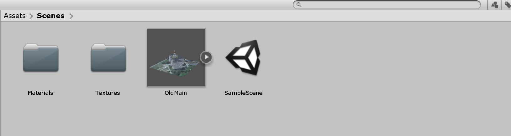
If the above method does not work for your case, you can always simply add the skp model into the editor by dragging and dropping it into the folder structure. You may have noticed that the Building object we have imported looks rather dull and is missing lots of textures and materials. To fix this problem, we need to extract all the materials and textures from the prefab of the model so that Unity knows how to map them. Select the prefab of the model you have imported into your folder. You can see that in the inspector menu it is detected that this is a SketchUp model, but all the materials for the individual components of this model are missing (labeled as none).
To fix this, click on the “Extract Textures …” button in the inspector panel. Create a new folder in the pop-up window and rename it to “Textures”, and then click on “Select Folder”. Do the same for Materials by clicking on the “Extract Materials …” and creating a new folder called “materials”. Once done, the model should have all the materials and textures added to it.
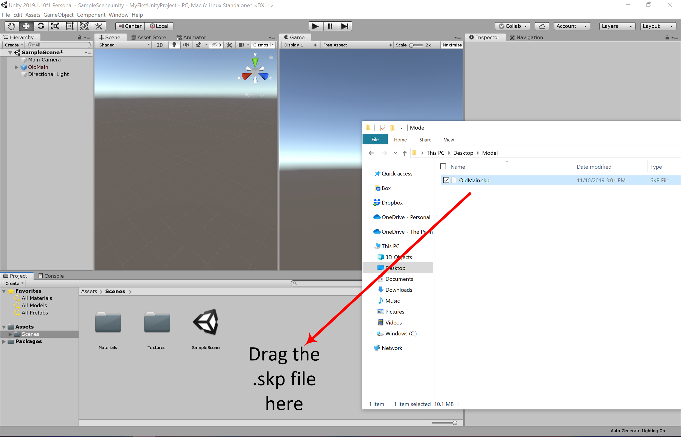
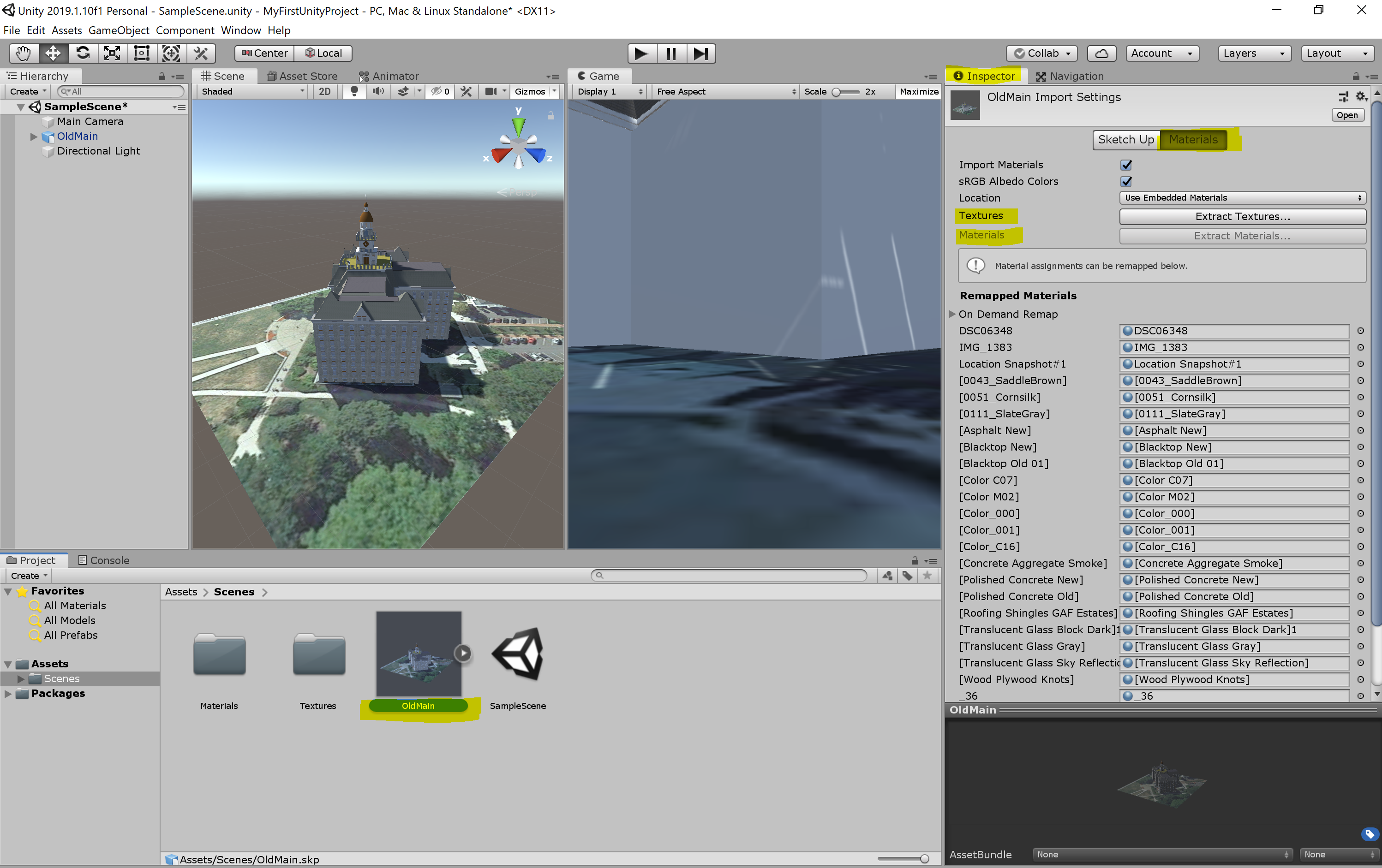
Adding the Model to the Scene
Adding the Model to the Scene
The next thing we are going to do is place the Old Main model in the Scene and make a few more changes to the Scene.
- 5.1 To add the model to the Scene, drag it from the Assets pane to the Hierarchy Window and drop it somewhere into the area below the “Main Camera” and “Directional Light” GameObjects. Most likely, things will look a bit strange in the Scene view because the building model is so large that it contains the current viewing position as well as the locations of the camera and lighting source. So as a first step to fix this, double-click the OldMain object in the Hierarchy Window and then zoom out a bit until you see the building somewhat similar to what is shown in the screenshot below.
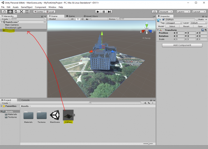 Credit: Unity 3D [137]
 - 5.2 While we now can see the entire building in the Scene Window, the camera and lighting source are still inside the building. So what you should do is scale down the “OldMain” object by a factor of 0.04. You can do this by selecting “OldMain” and directly editing the scale values in the Inspector Window. An alternative approach would have been to use the Scaling Tool as explained in one of the videos earlier in the lesson. But since we want a factor of exactly 0.04, directly editing the numbers is easier here. In addition, we want to turn the building around the Y axis by 180° so that the side facing the sunlight is the front side.
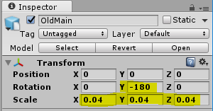 Credit: Unity 3D [137]
 -
5.3 If you select the “MainCamera” and look at the Preview (or try out Play Mode), you will see that this is now quite a bit away from the building. So let us place the camera such that we have a nice view of the building from the sunny side and the building roughly fills the entire picture. Remember that one way to do this is by changing the Scene view to the desired perspective and then use “Align With View”.
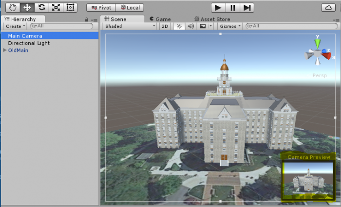 Credit: Unity 3D [137]
 - 5.4 Finally, press Play to enter Play Mode and have a quick check whether things are looking good in full size. You can click on the small drop-down icon at the top right of the Game Window and click “Maximize” to maximize the window. Stopping Play Mode will switch back to the Scene Window and the normal layout.
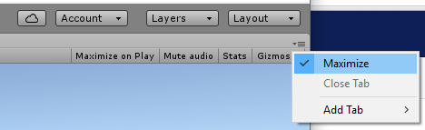 Credit: Unity 3D [137]
Making the Camera Keyboard-Controlled
Making the Camera Keyboard-Controlled
To make things at least a little bit interactive, we now want to be able to move the camera freely around in the scene using mouse and keyboard. Such interactivity is typically achieved by adding script components. So in this case, we want to attach a script to the “MainCamera” object that reads input from the mouse and keyboard and adapts the camera position and rotation accordingly.
We won’t teach you scripting with C# for this functionality because we can reuse some existing script. A resource for Unity scripts and extensions outside of the Asset Store is the Unity3D Wiki. As it happens, we find a script published under the Creative Commons Attribution-ShareAlike license there to realize the free-flight camera control we are looking for. The script can be downloaded here [104].
Let us have a very short look at the code. If you have some programming experience, you will recognize that there are a bunch of variables defined early on in the script (public float … = …) that will determine things like movement speed, etc. of the camera. These variables will be accessible from the Unity Inspector Window once we have attached this script to our camera. The actual functionality to control the camera is realized in the function Update() { … } . GetAxis(…) is used to read information from the mouse, while GetKey(…) is being employed to check the status of certain keys on the keyboard. The content of the variable called “transform” roughly corresponds to what you always see in the Transform section of the Inspector Window and is used here to change the camera position and rotation based on the user input. The Update() function of a script that is attached to a GameObject in the scene will be called for every tick (= rendered frame) when the project is executed. So in Play Mode, the keyboard and mouse will be constantly checked to achieve a smooth control of the camera.
Here are the steps to add this code as a script asset to our project and then attach it to the camera object in the Scene:
- 6.1 There are several ways how the steps to add the code can be performed. We here start with adding a new C# script file to our projects assets. Use "Assets -> Create -> C# Script" from the main menu. This adds a script to your Assets folder and it will appear as an icon in the Assets pane at the bottom of the editor. You are now supposed to give the script a name. It is important that the name of the script file is the same as that of the class being defined in the file, which in this case is “ExtendedFlycam”. So please use this name and make sure that the capitalization is correct (upper-case E and F).
 Credit: Unity 3D [137]
 - 6.2 You can click on the script icon to see the script code in the Inspector Window. Currently, this is just the standard template code for a Unity script that Unity generated automatically. Now double-click the script icon, which will open the script in Visual Studio. You may have to switch over to Visual Studio manually if the window doesn’t show up in the foreground on your screen. (Opening the visual studio could take a few minutes, and you might be asked to sign in, if you do not have an account, go ahead and create one, or explore the other options provided to you. You should be able to create a free personal account to use visual studio)
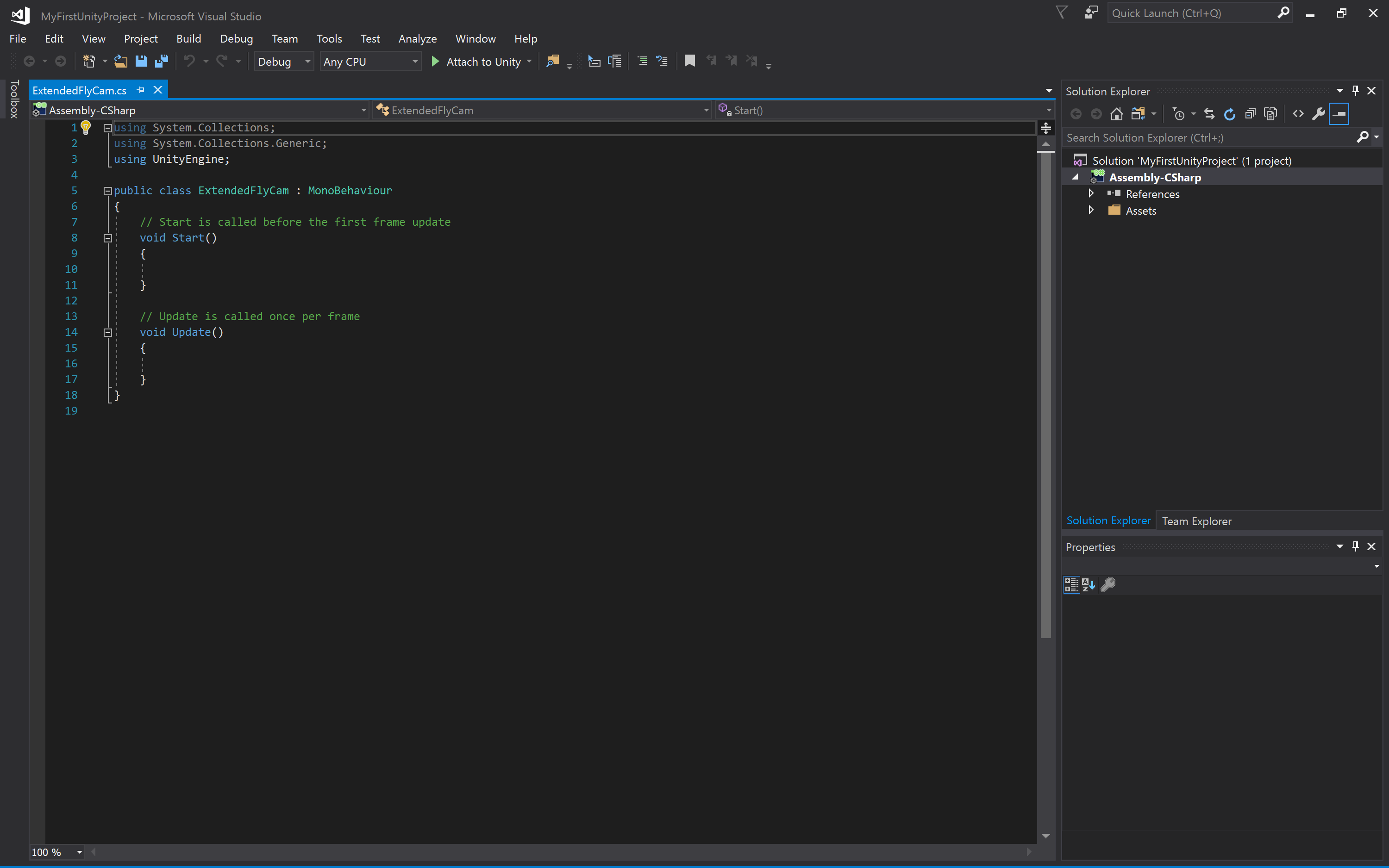 Credit: Visual Studio [138]
 - 6.3 You now see the template code in Visual Studio. Select everything and delete it so that you get an empty document. Then use copy & paste to copy the entire code from the text file you downloaded in the browser into the script window in Visual Studio. Press CTRL+S to save the changes, then switch back to Unity. Unity may report some warnings because some of the code uses deprecated functions but let’s ignore that here.
- 6.4 We now need to attach the script as a component to the “MainCamera” object. To do so, you can simply, select the “MainCamera” object and then drag the script from the Assets pane to the free area in the Inspector Window where the “Add Component” button is located. The script now appears as “Extended Flycam (Script)” in the Inspector Window and here you see the variables we talked about at the beginning exposed as parameters.
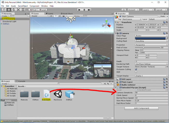 Credit: Unity 3D [137]
 - 6.5 It is now time to give this a try: Please enter Play Mode. You should immediately be able to turn the camera with the mouse and move the camera forward, backward, and sideways using the keys W, S, A, D or alternatively by using the cursor keys.
So you can now move the camera around the building (and actually also below it or into the model). The control is maybe a bit sensitive, so you may want to change some of the parameters of the camera script a bit (e.g. sensitivity and move speed). Just play around with the values. Since the mouse is now taken for the camera control, the best way to exit Play Mode is by pressing CTRL+P. - Now build a Windows application to share with your instructor for your assignment. Make sure that you zip the folder before you upload it.
First Game in Unity: Roll-the-ball
First Game in Unity: Roll-the-ball
The objective of this section is to get you familiar with the basics of C# programming in unity and the different awesome components (e.g. physics) offered by Unity. By the end of this section, you will be able to create a simple “Roll the ball” game as shown below:
Video: Roll the ball game (00:16) This video is not narrated.
The objective of the game is to roll a ball inside a box and collect all the available coins. The coins should simulate a rotation animation, capturing the attention of the player. Each time the ball hits a coin one point should be awarded to the player, a “cashier” sound effect played, and then that coin should disappear from the scene (i.e. collected).
The following steps will help you to first conceptualize what needs to be implemented and how it should be done, and second, guide you on how to utilize the Unity3D game engine to realize the needed game objects, mechanics, and functionalities.
- Close your unity editor and open the Unity Hub. Create a new project (you should already know the steps from the previous sections). Name your project “Roll the ball” and make sure the template is set to “3D”.
-
Before beginning the programming of the game behaviors described above, we need to set up the play area (i.e. the box) in which we will be moving the ball. To achieve this, we will use the default empty scene that comes with every new unity project. The scene should be already open and ready. To add the floor, in the Unity editor, go to the GameObject menu on top, then 3D Object -> Plane. This will add a plane to the scene. Make sure the Position and Rotation Parameters of the Transform component in the Inspector menu (Red box in the figure below) are all set to zero:
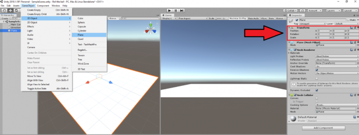 Credit: Unity [133]
Next, we need to add some color to our plane GameObject. To do this, in the project folder structure, right click on “Assets” and go to Create -> Folder. Rename this folder to “Materials”.
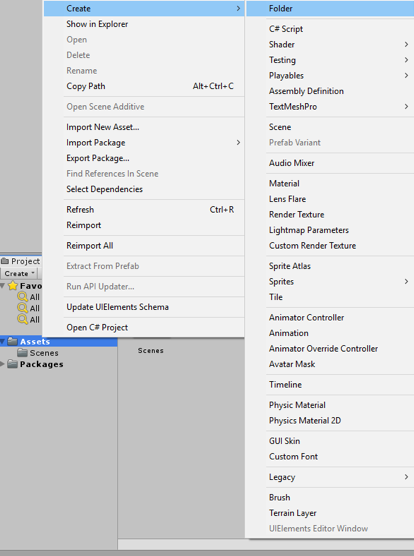 Credit: Unity [133]
Now right-click on the newly created materials folder and go to Create -> Material. Rename this material to “PlaneMat”.
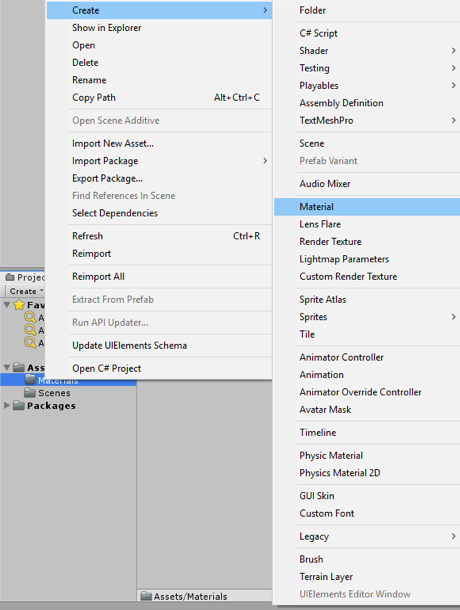 Credit: Unity [133]
Select the newly created “PlaneMat” and change its color from the Inspector panel on the right by clicking on the color picker next to the “Albedo”. Select a color of your liking.
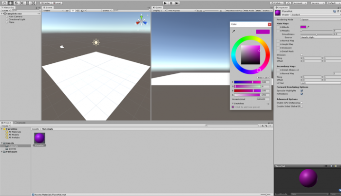 Credit: Unity [133]
Drag the “PlaneMat” onto the Plane GameObject in the scene. The Plane should now have color.
Next, we need to add four walls to the sides of the Plane so the Ball wouldn’t fall off. To do this, go to the GameObject menu on top, then 3D Object -> Cube. While the newly added Cube game object is selected set its transform parameters in the Inspector menu as depicted below:
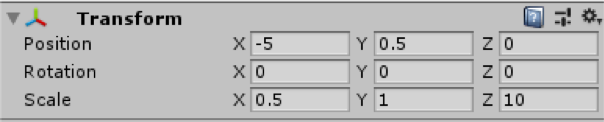 Credit: Unity [133]
Doing so will result in a wall placed on the right side of the plane. To have the proper view of the play area when running the scene or inspecting the scene output in the “Game” tab, set the position and rotation parameters of the “Main Camera” game object as shown below:
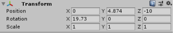 Credit: Unity [133]
Create a new material with a color of your choice inside the materials folder and name it “WallMat”. Drag this material onto the Cube game object that acts as the wall.
To add more meaning to our scene, rename the Plane and Cube game object to “Floor” and “Wall”, by right clicking on each and then selecting “Rename”.
Select the “Wall” game object, hold down the Ctrl button and press D (you can also right click on the wall gameobject and click on duplicate). if done correctly your “Wall” object should be duplicated and labeled “Wall (1)”. Change the X value of the position parameter of “Wall (1)” from -5 to 5. Using this simple process, a new wall is added to the left side of the plane.
Repeat the same procedure to add walls to the up and down sides of the planer. Simply duplicate the “Wall” object twice more and change its parameters as shown below:
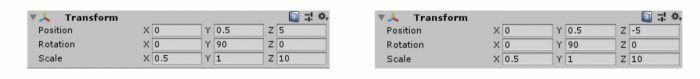 Credit: Unity [133]
At this stage, we should have the play area ready as this:
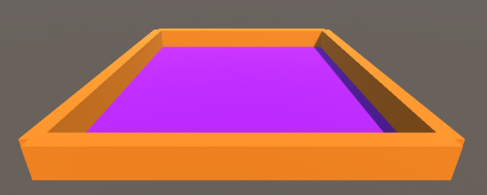 Credit: Unity [133]
Video: Roll the ball 1: A Summary of what we have done so far (Step 2) (03:19) This video is not narrated.
-
Next, we need to add a ball to our scene and make it controlled by the player and roll around the play area. To add a ball to the scene, go to GameObject -> 3D Object -> Sphere. Change the name of this game object to “Ball”. Set its transform parameters as shown below. And add a material (Create “BallMat”) with a color to it.
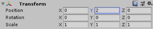 Credit: Unity [133]
If we play (
 ) the scene, you will realize that the ball will float in the air instead of dropping on the plane. The reason for this is that the ball game object does not have any physics attached to it yet. To fix this, select the ball game object, and in the Inspector panel, click on “add component”, search for “Rigidbody” and hit enter.
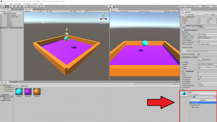 Credit: Unity [133]
Doing so will add a Rigidbody component to the ball game object. You may notice that the “use gravity” parameter of this component is checked by default, which will add gravity to this game object, and therefore it will drop onto the plane. Press play and see the result.
-
Rolling the ball: To enable the player to control the movement of the ball, we will use the arrow keys (the up, down, left, and right keys) on the keyboard. The idea is that by pressing the up arrow key we will make the ball roll forward, the down arrow key, backward, and the left and right arrow keys, to the sides. To achieve this, we will need to do a little bit of C# programming using the physics engine of Unity.
Create a new folder in the project panel called “Scripts”. Right-click on this folder, select Create -> C# Script. Rename this script to “BallMovement” (Make sure you use the same exact spelling for the script name -case sensitive- if you are planning to copy the source code!). Drag this script onto the Ball game object. Double click on the script to open it in Visual Studio (this could take a while, and you might be asked to log in. You can either create an account or explore different options provided to you). Our simple ball movement script should look like this (Please read the comments in the code for further explanation). Either type or copy (make sure the name of the class i.e. “BallMovement” is spelled exactly as you have name named the script file) the following code into your script (note, the lines in green are comments are not executed by the engine, they are just extra explanation for you to understand the logic behind the code. Therefore, if you decide to type the following source code into your script, you do not need to write the lines in green):
using System.Collections; using System.Collections.Generic; using UnityEngine; public class BallMovement : MonoBehaviour { // we need to define a variable that controls for the speed with which the ball rolls // the declaration of variables is done here // the type of the variable is float and its label Speed. The float type means that the value of Speed can be with precision points e.g. 15.5 public float Speed; // FixedUpdate is called several times per frame which will create the illusion of smooth movement void FixedUpdate() { // we need to take the input from the arrow keys pressed by the player. By default in unity, the left and right arrow keys are labeled as "Horizontal" and the up and down arrow keys as "Vertical" // we will define two variables where the value of each will be set "several times per frame" if the player presses the HorizontalMovement (i.e. the left or right key) and/or the VerticalMovement (i.e. the up or down key) float HorizontalMovement = Input.GetAxis("Horizontal"); float VerticalMovement = Input.GetAxis("Vertical"); // since we are dealing with three dimensional space, we will need to define a 3D vector based on which the ball should move. As such, we define a Vector3 called MoveBall that takes three parameters of X,Y,Z // movement on the X axis will be our HorizontalMovement (i.e. the left or right key) and on the Z axis the VerticalMovement (i.e. the up or down key). As we do not want to move the ball in the Y axis in the 3D space (i.e. up and down in the 3D space), the Y value will be set to 0 Vector3 MoveBall = new Vector3(HorizontalMovement,0,VerticalMovement); //lastly, we will need to access the physics component of our ball game object (i.e. the Rigidbody) and add a force to it based on the values of the vector we just defined. We will multiple this force value with our Speed variable to be able to control the Speed of the force as we wish. gameObject.transform.GetComponent
<Rigidbody>().AddForce(MoveBall * Speed); } } Once you are done populating your script with the source code above, make sure you hit save. It is absolutely important to remember that every time we modify a script, we save it so that Unity updates the editor based on the changes we have made.
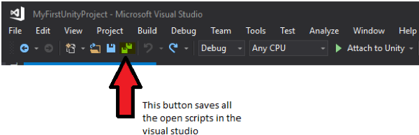 Credit: Unity [133]
If we go back to unity and select the ball game object, we will see that in the inspector panel under the “Ball Movement” script, there is now a “Speed” variable that we can set. Change its value to 25 and hit play. Use the arrow keys to roll the ball inside the play area.
Video: Roll the ball 2: A Summary of what we have learned so far (Steps 3 and 4) (02:11) This video is not narrated.
-
Adding coins to the scene: download the unity package file roll the ball assets [104]. Double click on this file, and it will open an “Import Unity Package” window inside unity. Click on import. Doing this will add two new folders in your assets hierarchy. One is called “Coin” which contains the model we will be using for the collectibles in our game. The other is called “Sounds” which will be covered in the next steps.
Go to the “Coin” Folder and select the Coin model. Drag this model into your scene and place it somewhere inside the play area. Change its transform parameters as follows:
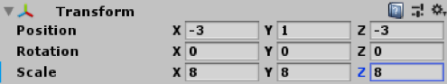 Credit: Unity [133]
We will now add a rotation effect to this coin to catch the attention of the player. To do this, create a new script inside the “Scripts” Folder called “CoinRotation”. Drag this script onto the coin game object. Double click on the script to open it in visual studio. Our simple coin rotation script will look like this (Please read the comments in the code for further explanation):
using System.Collections;
using System.Collections.Generic;
using UnityEngine;

public class CoinRotation : MonoBehaviour
{
    // we need to define a variable that controls for the speed with which the coin rotates
    public float RotationSpeed;


    void FixedUpdate()
    {
        // We need to instruct this object to constantly rotate around its own Y axis (i.e. up)
        // this is done by accessing the transform component of this gameobject and using the built-in RotateAround unity function
        // this function takes three parameters. first one indicates the point in the 3D space where the rotation should happen. Since we want the coin to rotate around itself, we will pass the position of the coin itself as this parameter
        // the second parameter indicates around which axis should the game object rotate. we will set this to the up axis so the coin rotates around the Y
        // the third parameter indicates the speed with which the coin should rotate. for this we will use our RotationSpeed variable
        gameObject.transform.RotateAround(gameObject.transform.position, transform.up, RotationSpeed);

    }
}
If we go back to unity and select the coin game object, we will see that that in the inspector panel under the “Coin Rotation” script, there is now a “Rotation Speed” variable that we can set. Change its value to 15 and hit play. The coin should be continuously rotating around its Y-axis.
Use the arrow keys to roll the ball inside the play area and hit the coin. You will notice that the ball will go right through the coin. The reason for this is that there is no collision happening between these two game objects. The ball game object has a Sphere collider attached to it by default, but the coin game object does not have a collider. Select the coin game object, in the Inspector panel select add component, search for “Box collider”, and hit enter.
Play the scene and try to hit the coin with the ball again. You will notice that this time, the two objects will collide. We would need to have colliders on both objects to be able to determine when they “hit” each other. We need this to be able to collect the coins (i.e. remove the coin from the scene when the ball hits it). You may have noticed that during the collision, the coin will momentarily block the movement of the ball until it slides to either side of the coin and keeps rolling based on the force behind it. We do not want the player to experience this effect. In contrast, we want the game to be able to detect exactly when the two objects are colliding, but we do not want them to block each other in any way. The collision system of Unity can help us in achieving this goal using “Trigger”. If you select the coin game object, you will notice that under the “Box Collider” component that we just added, there is a parameter called “Is Trigger”. Enable this parameter by clicking on the CheckBox next to it. If we hit play, we can see that although we have colliders attached to both objects, the ball will not be blocked by the coin anymore.
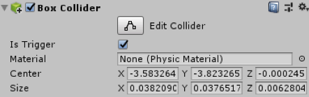 Credit: Unity [133]
 -
Coin collection: create a new script called “CoinCollection” and attach it to the Coin game object. Open the script in visual studio and modify the code based on the instructions below:
using System.Collections;
using System.Collections.Generic;
using UnityEngine;

public class CoinCollection : MonoBehaviour
{

    // this is the default unity function that will be called whenever two objects collide and one has the Trigger parameter enabled
    // the argument "other" refers to the object that hits the game object this script is attached to.
    private void OnTriggerEnter(Collider other)
    {
        // In this case the we want to check if the "other" is the "Ball"
       // Make sure your ball gameobject is named “Ball”, otherwise you will receive an error!
        if (other.name == "Ball")
        {
            // if this condition is correct and indeed the Ball game object has hit this game object where the script is attached (i.e. the coin), we will remove this game object
            Destroy(this.gameObject);
        }
    }
}
Duplicate the coin game object several times and spread the coins across the play area. Play the scene and hit the coins. You will see that as soon as the ball hits a coin, that particular coin will be “destroyed”.
Video: Roll the ball 3: A summary of what we have learned so far (Steps 5 and 6) (03:41) This video is not narrated.
-
Point system: Before destroying a coin upon collision with the ball, we want to reward the player with a point for managing to collect it. To implement this functionality, create an empty gameobject by going to GameObject -> “Create Empty”. Rename this empty game object to “Point System”. Create new script called “PointSystem” and attach it to the “Point System” game object. Open the script and modify the code based on the instructions below:
using System.Collections;
using System.Collections.Generic;
using UnityEngine;

public class PointSystem : MonoBehaviour
{
    // we need to have a variable that holds the value of the points we aggregate
    public int Points;

    // we need to defined a GUIStyle profile for our graphical user interface (GUI) that shows the value of points to change its font size, shape, etc.
    public GUIStyle PointStyle;

    // this is the default unity graphical user interface (GUI) function. It will render GUI elements on the screen on a specific 2D coordinate
    private void OnGUI()
    {
        // a GUI label to show the value of the aggregated points, place at the X=10, Y=10 coordinates, with width and height of 100, the next argument is the content that the label shows which is in this case
        // a numerical value. we need to convert the numerical value to a string (text) to be able to show it on the label. The last argument indicates which GUIStyle profile should be used for this label
        GUI.Label(new Rect(10,10,100,100),Points.ToString(),PointStyle);
    }
}
The script described above is responsible for holding the value of the points the player aggregates and visualizing it on the screen. To increase the points however, we will add a line to the script responsible for detecting when the ball hits a coin. For this go back to the “CoinCollection” script and modify it based on the instructions below:
using System.Collections; using System.Collections.Generic; using UnityEngine; public class CoinCollection : MonoBehaviour { // this is the default unity function that will called whenever two objects collide and one has the Trigger parameter enabled // the argument "other" refers to the object that hits the game object this script is attached to. private void OnTriggerEnter(Collider other) { // In this case the we want to check if the "other" is the "Ball" if (other.name == "Ball") { //if this condition is correct and indeed the Ball game object has hit us, access the Point System game object, then the PointSystem script attached to it, and increase the Points variable by 1 GameObject.Find("Point System").GetComponent<PointSystem>
().Points += 1; // we will remove this game object where the script is attached to (i.e. the coin) Destroy(this.gameObject); } } } Next, select the “Point System” game object. On the inspector panel on the right, in the “PointSystem” Script attached to it expand the “Point Style” GUIStyle and change it as instructed below:
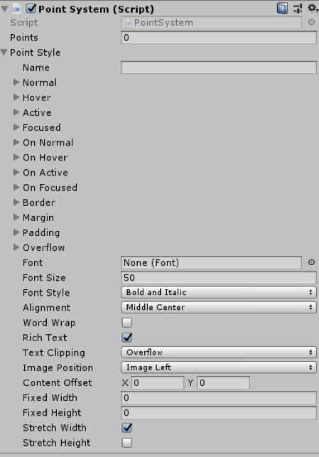 Credit: Unity [133]
Press play and start aggregating points!
-
Collection sound: another feature we need to add to our game is a sound effect. We want to play a “cashier” sound effect each time the ball hits a coin. To achieve this. Create a new empty game object and rename to “Sound Management”. Select this newly created game object and click on “Add Component”, search for “Audio Source” and hit enter.
Navigate to the “Sounds” folder in your project hierarchy and drag the “CashierSound” clip to the “AudioClip” field in the “AudioSource” component we just added to our audio management game object. Uncheck the “Play On Awake” parameter of the “AudioSource” component so the sound clip does not play as soon as we start the scene.
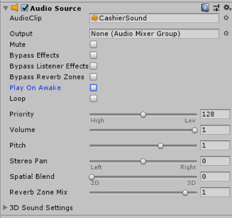 Credit: Unity [133]
Next, we need to instruct the game to play the audio clip whenever we collect a coin. To achieve this, modify the “CoinCollection” script based on the instructions below:
using System.Collections; using System.Collections.Generic; using UnityEngine; public class CoinCollection : MonoBehaviour { // this is the default unity function that will called whenever two objects collide and one has the Trigger parameter enabled // the argument "other" refers to the object that hits the game object this script is attached to. private void OnTriggerEnter(Collider other) { // In this case the we want to check if the "other" is the "Ball" if (other.name == "Ball") { //if this condition is correct and indeed the Ball game object has hit us, access the Point System game object, then the PointSystem script attached to it, and increase the Points variable by 1 GameObject.Find("Point System").GetComponent
<PointSystem>().Points += 1; // access the audio management game object, then the AudioSource component, and play GameObject.Find("Sound Management").GetComponent <AudioSource>().Play(); // we will remove this game object where the script is attached to (i.e. the coin) Destroy(this.gameObject); } } } Video: Roll the ball 4: A summary of what we have learned so far (steps 7 and 8) (03:13)
Hit play and enjoy your creation!
Note
It is NOT the goal of this course to teach you C# programming. However, without basic knowledge of C# you will not be able to create a rich virtual experience. The provided scripts to you in this exercise are fully commented for your convenience. Please take the time to study them, as they will prove to be rather useful in the next session.
Tasks and Deliverables
Tasks and Deliverables
Assignment
The homework assignment for this lesson is to report on what you have done in this lecture. The assignment has two tasks and deliverables with different submission deadlines, all in week 8, as detailed below. Successful delivery of the two tasks is sufficient to earn the full mark on this assignment. However, for efforts that go "above & beyond" by improving the roll-the-ball game, e.g. create a more complex play area -like a maze- instead of the box, and/or make the main camera follow the movement of the ball, you could be awarded one point if you fall short on any of the other criteria.
To help with the last suggested extra functionality, use the following script and attach it to the main camera:
using System.Collections;
using System.Collections.Generic;
using UnityEngine;

public class FollowBall : MonoBehaviour
{
    // reference to the ball game object
    public GameObject Ball;

    // a vector3 to hold the distance between the camera and the ball
    public Vector3 Distance;

    // Start is called once before the first frame update
    void Start()
    {
        // assign the ball game object
        Ball = GameObject.Find("Ball");

        //calculate the distance between the camera and the ball at the beginning of the game
        Distance = gameObject.transform.position - Ball.transform.position;
    }
    // This called after the Update finishes
    void LateUpdate()
    {
        // after each frame set the camera position, to the position of the ball plus the original distance between the camera and the ball
// replace the ??? with your solution
        gameObject.transform.position = ???;
    }
}
Task 1: Find and Review Unity 3D/VR Application
Search the web for a 3D (or VR) application/project that has been built with the help of Unity. The only restriction is that it is not one of the projects linked in the list above and not a computer game. Then write a 1-page review describing the application/project itself and what you could figure out how Unity has been used in the project. Reflect on the reasons why the developers have chosen Unity for their project. Make sure you include a link to the project's web page in your report.
Deliverable 1: Submit your review report to the appropriate Lesson 7 Assignment.
Grading Rubric Unit 3D/VR Application Review
| Criteria | Full Credit | Half Credit | No Credit | Possible Points |
|---|---|---|---|---|
| URL is provided, the application/project uses Unity, is not already listed on this page, and is not a game. | 2 pts | 1 pts | 0 pts | 2 pts |
| The report clearly describes the purpose of the application/project and the application itself. | 3 pts | 1.5 pts | 0 pts | 3 pts |
| The report contains thoughtful reflections on the reasons why Unity has been chosen by the developers. | 3 pts | 1.5 pts | 0 pt | 3 pts |
| The report is of the correct length, grammatically correct, typo-free, and cited where necessary. | 2 pts | 1 pts | 0 pts | 2 pt |
| Total Points: 10 |
Task 2: Build a Simple “Roll-the-ball” Game
If you follow the detailed instructions provided in this lecture, you should be able to have a fully working roll-the-ball game.
Deliverable 2: Create a unity package of your game and submit it to the appropriate Lesson 7 Assignment.
You can do this by simply going to the Assets in the top menu and then selecting “Export Package”.
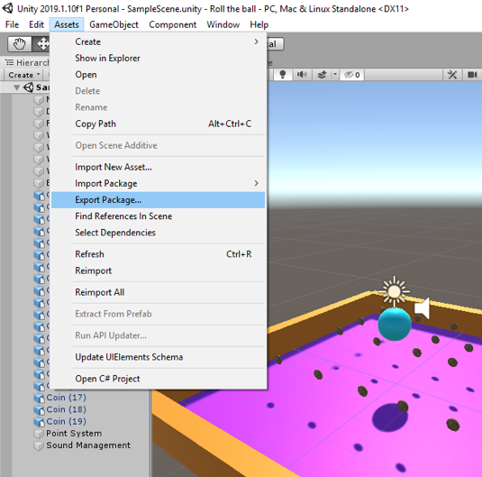
Make sure all the folders and files of your project are checked and included in the package you export (you can test this and import your package in a new Unity project to see if it runs).
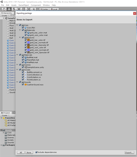
If you choose to implement the functionality of the main camera to follow the ball movement, please explain your solution as a comment in your script. You can add comments (texts in green) in C# by using “//”.
Helpful advice:
We highly recommend that, while working on the different tasks for this assignment, you frequently create backup copies of your Unity project folder so that you can go back to a previous version of your project if something should go wrong.
Grading Rubric for Roll-the-Ball game
| Criteria | Full Credit | Half Credit | No Credit | Possible Points |
|---|---|---|---|---|
| Your game runs smoothly and as intended without any errors or strange behavior | 6 pts | 3 pts | 0 pt | 6 pts |
| Your project is complete and has all the required functionalities (coin rotation, collection, and sound effect). | 3 pts | 1.5 pts | 0 pt | 3 pts |
| Your Unity package has a proper folder structure, and all the files have meaningful names like it was done in the instructions | 1 pt | .5 pts | 0 pts | 1 pt |
| Total Points: 10 |
Summary and Tasks Reminder
Summary and Tasks Reminder
In this lesson, you learned about the Unity3D game engine and the role it can play in creating 3D and VR applications. You should now be familiar with the interface of the Unity editor and the main concepts of Unity and be able to create simple projects and scenes. In the next lesson, we will explore other features of Unity for building 3D applications, including adding an avatar to a scene, creating a camera animation, importing resources from the Unity Asset Store, and creating a 360° movie that can be uploaded to YouTube and be watched in 3D on a mobile phone via the Google Cardboard.
Reminder - Complete all of the Lesson 7 tasks!
You have reached the end of Lesson 7! Double-check the to-do list on the Lesson 7 Overview page to make sure you have completed all of the activities listed there before you begin Lesson 8.
Lesson 8: Unity II
Overview
Overview
This will be another practical lesson with several hands-on walkthroughs to explore other features of Unity that are useful for building 3D applications. This includes adding an avatar to a scene such that the user can walk in an environment around buildings; and creating a camera animation to generate a video with a pre-programmed camera flight over the scene. We will learn to import resources from SketchUp, the Unity Asset Store, and to create a 360° movie that can be uploaded to YouTube and then watched in 3D on a mobile phone via the Google Cardboard.
Learning Outcomes
By the end of this lesson, you should be able to:
- Import models from SketchUp into Unity
- Create camera flights and use the Unity Animation View
- Explain different ways to create VR applications with Unity
- Import assets from the Unity Asset Store and add them to a scene
- Create a 360° video in Unity viewable with the Google Cardboard
Lesson Roadmap
| To Read |
|
|---|---|
| To Do |
|
Questions?
If you have any questions, please post them to our "General and Technical Questions" discussion (not e-mail). I will check that discussion forum daily to respond. While you are there, feel free to post your own responses if you, too, are able to help out a classmate.
3D Applications in Unity
3D Applications in Unity
In Lesson 2, we introduced 3D application building software like Unity as part of a general 3D/VR application building workflow. The main role of 3D application building software can be seen in providing the tools to combine different 3D models into a single application, to add dynamics (and, as a result, making the model more realistic), and to design ways for a user to interact with the 3D environment. We also learned that 3D application building software typically provides support to build stand-alone applications for different target platforms including common desktop operating systems, different mobile platforms, and also different VR devices.
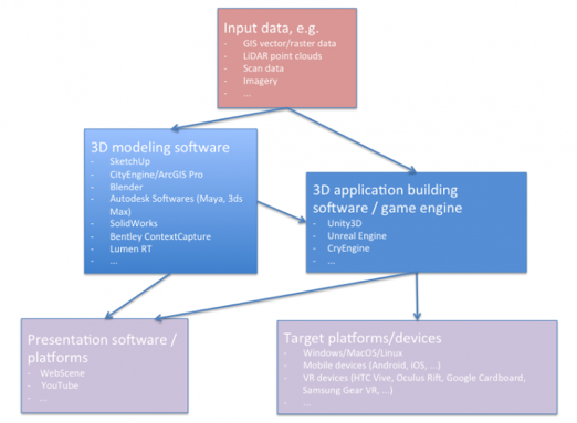
A schematic diagram outlines the following information (in summary):
-
Input data (in a variety of formats) imported into either a 3D modeling software or a 3D application building software such as a game engine
-
In 3D modeling software, 3D models are created either manually or automatically based on computational methods
-
The resulting models could be either directly used for visualization (i.e. on the web) or imported into 3D application building software such as Unity3D for more elaborate functionalities
-
The application made from game engines (e.g. Unity 3D) can be deployed on both web and a variety of platforms including VR headsets
In the previous lesson, you already use some of the tools available in Unity for adding dynamics and interaction possibilities to a 3D scene in the form of giving the user control over the movement of gameobjects, animating gameobjects via scripting, collision detection, basic graphical user interface, and scripting more advanced behaviors, e.g. collecting coins and awarding points. As you have already experienced, adding behavior to your gameobjects is done either through standard unity components (e.g. rigidbody, colliders, etc.) or through scripting.
In this lesson, you will gain more practical experience with other tools available in Unity. But first, let's start the lesson with a brief overview of general tools utilized by Unity for 3D application building. As we go through this first part of the lesson, you will begin to realize that you have already used some of these tools in the previous lesson! We roughly divided the following list into ways to make a scene dynamic and ways to add interactions. However, this is a very rough distinction with certain aspects or tools contributing to both groups. In particular, scripting can be involved in all of these aspects and can be seen as a general-purpose tool capable of extending Unity in almost unlimited ways (e.g. in the previous lesson we used scripting to both animate our coins by constantly rotating them, as well as collecting them upon collision with the ball).
Tools to make a scene dynamic:
-
Animations: Animations [139] obviously are one of the main tools to make a scene dynamic. We will talk about animations quite a bit in this lesson and you will create your own animation clip to realize a camera flight over a scene. Here are a few examples of animations that can make a scene more realistic and dynamic:
- animations of otherwise static objects to make them appear more realistic, e.g. a plant or flag moving slightly as if affected by wind, opening and closing animations of a door
- animations to simulate time of day: This can largely be accomplished by using animation to move a Directional Light object along a pre-programmed trajectory to simulate the movement of the sun
- animation to move the main camera along a pre-programmed trajectory (see the third walkthrough of this lesson)
- animations for movement of dynamic objects populating the scene, e.g. humans or cars moving through the scene in different ways (walking vs. running) and along different trajectories
- State machines: Many objects in a dynamic 3D environment can always be in one of several possible states. For instance, a traffic light may be in the states red, yellow, green; a car may be either parked, standing still with engine running, or driving; and an artificial humanoid avatar in the scene can have many possible states associated with such as sitting, standing, walking, running, reaching, etc. The transition between two possible states of a GameObject can be triggered by events. For instance, a human avatar can be programmed to switch from the "sitting" state to the "standing" state when another humanoid avatar enters the same room. State machines [140] are the Unity tool for realizing this idea and are often used to provide acting agents with some behavior, potentially involving AI methods to make the behavior appear realistic. Often, each state in the state machine of a GameObject is associated with a particular animation.
- Particle systems: While animations allow for adding dynamics to solid objects modeled as 3D meshes, there are visible effects in a dynamic environment that do not lend themselves to be modeled and handled in this way. Examples are smoke and flames, liquids, clouds, rain, and snow, etc. Particle systems [141] are the most common approach to model these things and can be easily created in Unity. A particle system consists of several, up to a large number of particles, which are simple images or meshes, that are moved and displayed together, for instance, to form the impression of smoke. A particle system has many parameters to control the properties of the particles, their movement and dynamics, their lifetime, etc.
- Physics: Physics is an important part of a really dynamic scene and needed to simulate the behavior of objects under gravity, collisions, and other forces. Unity's physics engine [142] is capable of simulating the behavior of solid objects under these forces. You have already used some parameters of the physics engine in the previous lesson including rigidbody and collider.
- Sound: Audio is another important input mode to make a 3D scene appear more realistic and increase its immersiveness. Sometimes you may also just want to add some nice music in the background of your application or add some commentary that is played to explain something in the scene or give instructions to the user. Unity's audio support [143] is essentially based on the idea of attaching AudioListener and AudioSource components to GameObjects in the scene. The AudioListener is typically attached to the main camera. An AudioSource attached to an object can be set up so that the played audio track gets louder when the camera approaches that object. Unity supports real 3D spatial sound which also allows the user to tell which direction a sound is coming from. You have already used an example of the AudioSource in the previous lesson for coin collection.
Tools to add interactions:
- User input: We already saw how keyboard input can be used to control the movement of an object (the ball in our previous lesson) in the scene based on some scripting and manipulation of the transformation parameters of an object. Similarly, user input can be used to interact with the objects in the scene in some other way such as opening doors, pushing/pulling some other object, pressing a button, etc.Unity's Input Manager [144] can be used to configure the input devices for a project. We will see the use of mouse as in input controller in the next lesson.
- GUI: 3D applications still make use of classical 2D graphical user interface (GUI) elements to display information to the user, provide selection choices, or collect other user input. For instance, a GUI menu could be used to allow the user to immediately jump to one of several pre-defined locations in the nice or a dialog box can be used to allow the user to enter input values for important variables like movement speed. However, Unity's UI system [145] is a bit out of the scope of this introductory course. The Unity web page [146] contains a lot of video tutorials explaining the different UI elements if you are interested in this aspect. We have already experienced creating a very simple GUI label that holds the value of the “points” awarded to a player in the previous lesson. In addition, here is a very short video demonstrating a simple Unity UI for triggering different animation states of a face, connecting back to the things we discussed above, regarding animations and state machines:Overview of An Interactive Interface Demo in Unity [147]. The Unity Assets Store contains thousand of assets related to creating menus and GUI in general.
- Complex 3D/VR interactions: IIn particular with the advent of special VR controllers to complement consumer-level head-mounted displays, new ways to interact with objects in a 3D or VR setting are conceived every day. Modern VR controllers, such as the HTC Vive Controller [148], not only combine buttons, trackpads, and triggers that allow for triggering interactions by certain clicks, but the fact that the position and orientation of the controllers in the room are tracked allows for completely new interactions by touching or pointing at objects in the scene, or by performing complex gestures with the controllers, e.g. for moving, rotating, or scaling other objects, teleporting in the scene, or measuring distances or volumes. Template scripts for many of these interactions are already publicly available. Devising and implementing completely new ways to interact with objects in the scene typically requires quite a bit coding though.
Since this is a Geography/GIS class, we also want to briefly mention that support for importing GIS data into 3D modeling and application building software to employ it as part of 3D or VR application is slowly increasing. The image below shows a world map GameObject consisting of meshes for all countries in the Unity editor. The meshes were created from an ESRI shapefile using BlenderGIS, an add-on for importing/exporting GIS data into Blender. Then the meshes were exported and imported into Unity as an Autodesk .fbx file.
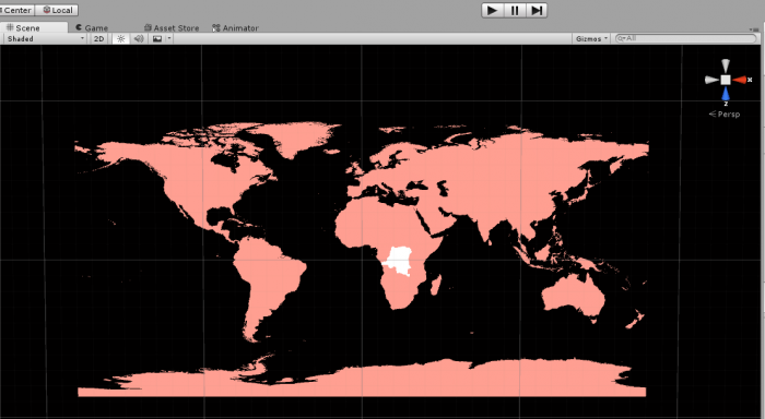
Recently, Mapbox announced the Mapbox Unity SDK [149], providing direct access to Mapbox hosted GIS data and Mapbox APIs within Unity. We believe that more initiatives like this can be expected for the near future, partially driven by the huge potential that current developments in VR and AR technology offer to GIS software developers.
Walkthrough: From SketchUp Model to Unity
Walkthrough: From SketchUp Model to Unity
In this walkthrough, we will see how we can import a 3D model from a SketchUp into Unity. Although the Unity Asset Store contains a large repository of free 3D models that you can use in your projects, depending on the requirements, it might be needed to import custom models into Unity. As you have already gained some experience in modeling 3D objects in SketchUp, it will be useful to see how you can import your model directly into Unity and add behaviors to it. In this walkthrough, we will import a SketchUp model of the “Walker” building into Unity, extract its materials and textures, and add it to a scene. Then, we will add a first-person controller prefab from the standard assets of unity which will enable us to walk around our scene.
You should still have the Unity project “MyFirstUnityProject” from the beginning of the previous lesson. Open your Unity Hub and open the “MyFirstUnityProject” (if you do not have this project anymore, follow the instructions from the previous lesson on how to create it. Make sure you also import the first package you used in the previous lesson – download here [104]). We will use this project to perform this walkthrough. Download the following Walker Laboratory [135] SketchUp file and once the download is completed, navigate to the location where it is downloaded (by default it should be in your User\[your username]\Downloads).
In the Unity editor, create a new folder in your project folder structure and rename it to “Walker Building”. Drag and drop your downloaded SketchUp file into this folder. Create a new scene in the same folder, by right-clicking on the folder from the folder structure panel -> create -> Scene. Name this scene “WalkerScene”. Open this scene and drag your WalkerLabaratory SketchUp model into the scene. Reset its position and rotation values to zero. Change the position of the Main Camera in the scene so the building is within its view. Change the X rotation of the directional light to adjust the lighting/show of your scene.
You may have noticed that the Building object we have imported looks rather dull and is missing lots of textures and materials. To fix this problem, we need to extract all the materials and textures from the prefab of the model so that Unity knows how to map them. Select the prefab of the model you have imported into your folder. You can see that in the inspector menu it is detected that this is a SketchUp model, but all the materials for the individual components of this model are missing (labeled as none).
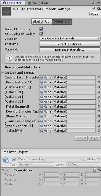
To fix this, click on the “Extract Textures …” button in the inspector panel. Create a new folder in the pop-up window and rename it to “Textures”, and then click on “Select Folder”. Do the same for Materials by clicking on the “Extract Materials …” and creating a new folder called “materials”. Once done, the model should have all the materials and textures added to it.
Unity SketchUp (01:39) This video is not narrated.
To add a first-person controller, we will use the default FPSController prefab on unity. This is the same prefab that you have used in the first part of the previous lesson. Navigate to the “Standard Assets” folder -> “Characters” -> “FirstPersonCharacter” -> “Prefabs”. Drag and drop the FPSController prefab into your scene. Place the FPSController somewhere on the plane (you can start with X=0 and Z=0 for position and then move the FPSController along these axes) and make sure the Y value of its position parameter is set to 1. Rotate the FPSController GameObject so it faces the building. If you play the scene now, you will notice that the FPSController will fall through the plane. This is because we have not yet attached colliders to our objects. The FPSController prefab already has a collider so all we need to do is to add colliders to the plane and all the children of the Walker GameObject.
To achieve this, you have two options. You should either select all the child objects of the building prefab that has a “Mesh renderer” component attached to it and add a “Mesh collider” to that object manually. Since these objects have meshes, the physics engine of Unity will use the shape of the mesh to create a collider with the same shape around that object. Or you can select the Walker prefab from your project folder and check the “Generate Colliders” parameter in the inspector menu under SketchUp option, and then press “Apply”. Press play, and you should be able to navigate on this plane using the WASD keys on your keyboard and look around using your mouse.
Unity SketchUp 2: 01:22 This video is not narrated.
Once you are done experimenting with your new creation, disable the FPSController GameObject by clicking on it once, and then unchecking it from the inspector panel.
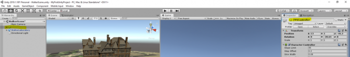
In the next walkthrough, we will cover animating a camera and for this, we need to use the static Main Camera in our scene.
Animations and State Change in Unity
Animations and State Change in Unity
Animations are one of the main methods to bring some life into a 3D scene in Unity and make it dynamic. Objects in the scene may be permanently going through the same looped animation (think of the leaves of trees moving in the wind) or they may be in a particular animation state that can change, potentially triggered by some external event (think of a human avatar that can switch from a walking animation to a running animation and that may have many other animations associated with).
The theoretical concept behind this idea is the notion of a State Machine: Each GameObject is always in one of a pre-defined set of states (state for walking, state for running, etc.), potentially associated with a particular animation. The transition from one state to another is triggered by some event which, for instance, can be some user input, a collision with another object, or simply a certain amount of time passed. The states with possible transitions between them form the object's state graph as shown in the image below. The state graph together with a pointer to the object's current state when the project is running constitute the object's state machine.
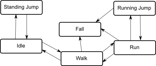
In this course, we will use animations only to animate the main camera to create a camera flight over the scene. Other uses for animations for 3D/VR applications could be making objects like plants more realistic, creating movable objects like doors, or populating the environments with dynamic entities like people or cars. Our camera flight will only need a single animation and, hence, state. So we won't have to deal with complex state graphs and the transitions between states. Nevertheless, please watch at least the first 90 seconds of the following video to get a bit of an understanding of the Unity's Animator component and controller and what happens under the surface when working with Animation State Machine. Don't worry if some of the details don't get completely clear.
The Animator Component (03:45)
In order to animate the properties of game objects in Unity we use the Animator Component. Animator components have a number of properties which may differ depending on what you are animating. For example, a 3D humanoid character will require different settings than a 2D sprite. Here we have a scene with a model in it. The model has an animator component attached. The first property of the animator component stores a reference to an animator controller asset. Animator controllers are Unity generated assets that contain one or more state machines which determine which animation is being played while the scene is running. These state machines can be on multiple layers and use parameters of various types. To affect when they transition between states and blend. For example you can set the parameters of an animator controller from your scripts to tell it if the character is running, jumping or shooting a gun. It will then play and blend the animation automatically. The avatar is an asset that Unity creates when importing a 3D humanoid. It contains a definition of the skeletal rig the character has. When adding a character of this type to your scene the avatar field will automatically be filled in with an asset created for that character. Try to think of the avatar as the glue that binds the model to be animated to the animator. For generic objects without skeletal rigging an avatar is not required. The Apply Root Motion field determines whether the animation can affect the transform of the game object and is generally used with 3D humanoids. Root Motion is the core movement within an animation clip. For example imagine the difference between an animation of a character running on the spot verses one that is animated running a few paces forward. In the latter example we can use the motion of the character moving forward to drive the character around in our game. Looping that clip to give us realistic continuous motion. However, if you simply have animations that run on the spot you would uncheck Apply Root Motion and instead move the character via script. It is also possible to override this property entirely. This is done by creating a script with a call to the onAnimatorMove function and attaching it to your game object. See the documentation link below for more information on this. Animate Physics can be either checked or unchecked. When it is checked it means that the animations will be executed in time with the physics engine. Generally this is advised if what ever you are animating has a rigidbody. The Culling Mode of an animator effects whether or not the animations are being played while they're not being rendered. Always Animate means that the animations will play even while not being rendered. Based On Renderers means that the animation will only play while being rendered. Meaning that when the character is obscured from view animation will cease to save performance. With either option the root motion is applied as it would normally. That is if a character was being made to walk with root motion applied then they would continue to move even while not being rendered so that the character would end up in the correct place when they became visible again. Subtitles by the Amara.org community
The main tool for creating an animation in Unity is the Animation View. It's a very powerful but also slightly complex tool so that we will only get to know its basic features here. For details, please see the documentation available here [150]. The Animation View is for creating and editing animation clips as well as previewing them. Please watch the following short video to familiarize yourself with the idea of creating a camera animation clip in Unity using the Animation View. You do not have to try out what is shown in the video yourself; we will be doing this in the walkthrough in the next section (the walkthrough will slightly deviate from what is shown in the video though).
The Animation View (06:20)
The animation view allows you to create and modify animation clips directly inside Unity. It is designed to act as a powerful and straightforward alternative to external 3D animation programmes. For instance, if we wanted to have a camera fly around a scene to give a player an overview of a level we can create that animation for it in Unity. Here we have a scene with a camera in the corner. We would like to create an animation for that camera which will allow it to move from one side of the scene to the other. Since we want to make an animation for the camera we will want to ensure that it is selected in the Hierarchy view. We can then open the Animation view by clicking Window - Animation. Like any other view this is moveable resizable and dockable. There are many different buttons and options visible when you first open the Animation view. First and foremost is the animation drop-down. Here is where we can select our different animations to edit. Since we don't currently have any animations this drop-down is blank except for the ability to create a new animation. When you create a new animation you will be prompted for a name and a location to save the animation file. We will create an animation called CameraFlyThu and place it in the Animations folder. The Add Curve button allows us to choose which components of our object, or any child objects, we wish to modify with our animation. Each component can be expanded to view more options. To add a curve click the + sign next to the item you wish to add. Since we want our camera to fly around the scene we will add the transform's position and rotation. The timeline is where you will be able to establish the timing of your animation. The timeline is measured in frames and seconds. The red scrubber allows you to choose what frame you wish to modify. Next is the Record and Play buttons. When the record button is pressed changes made to the chosen object in the Scene view will be added automatically to the animation at the currently selected frame. The play button will allow you to preview your animation. The left and right arrows allow you to navigate through the keyframes of the animation. Next are the buttons which allow you to add keyframes and events to the currently selected frame. The Sample property determines how many frames make up one second of animation. Reducing this number makes our animations slower. At the bottom are two buttons that allow you to transition between dope sheet mode, which we are currently on, and curve view mode. With the record button pressed it can be very easy to rough out the animation that we want. Simply select the frame we want to modify and rotation in the scene view. and then set the desired camera position You will notice that a keyframe has been added to the timeline with the appropriate values. Properties that are currently being animated are highlighted in red in the Inspector. We can continue doing this for the various phases of our fly through animation. To preview the animation click the play icon next to the record icon in the animator view. If we were satisfied with our animation we could be done now. If we wanted to fine tune our animation however we would want to look at the curves mode. To enter the curves mode select the Curves button at the bottom of the animation view. Here we can see the various curves of our animation by selecting the corresponding component on the left. Again we can select a frame using the red red scrubber on the timeline. To modify a value on a curve click and drag a keyframe to the new desired value. To create a new keyframe click the Create Keyframe button, or double click on the curve. Right-clicking on a keyframe will pull up some of it's options. the most notable of these options is the ability to choose Free Smooth. This will create two handles are the keyframe which you can use to smooth the curve to your liking. Another way to control our curves is to choose the Broken option. This allows you to control each side of the keyframe indecently. In this example we will want to add a little variance to the exposition of the transform. Doing so will give us more of a weightless feel to our animation. Again we can do so by creating keyframes on the exposition curve and changing our values manually. The animations created in Unity have the same Inspector settings as animations made in external programmes. We can see these by selecting our clip in the Project view. Since we want our camera to fly across the screen only once, we best uncheck are Loop Time property. It is interesting to note that an animator is in charge of animation playback for generic objects the same as it is for humanoids. Unity has automatically added the animator to our camera and created an animator controller, a state machine and added it to this component The clip we just created is added to the state machine as the default clip that would be played at runtime. This means we can go on to record other clips and use the animator to decide when to play them. In this manner, once our animation clip is completed we can run our scene to see it in action. Subtitles by the Amara.org community
The Unity web page [151] has more videos related to animations available, dealing for instance with importing animations created in other software, creating animations for a humanoid avatar, etc. You won't need to know about these more advanced topics for this course, but if this a topic of interest to you, feel free to check these out.
Walkthrough: Creating a Camera Animation
Introduction
Walkthrough: Creating a Camera Animation
Introduction
In this walkthrough, we are going to program a camera flight over the Walker building using Unity's animation functionality similar to what you saw in the video from the previous section. Have the Walker Scene open. For your assignment, you will create this animation for the campus [104] with more buildings. (The building used in these instructions is the Walker building but you might see the name of Old Main in the hierarchy. That's just not using the right name. Hope it wont confuse you).
Initial Placement of the Main Camera
We should only have one active camera called “Main Camera” in the Scene. We will make the Main Camera to be the child of a general container object called “Camera Setups”. The animation for the camera flight will be defined for the parent object (Camera Setups) and applied to all its child entities. So use “GameObject -> Create Empty” to place the container GameObject in the scene. Change the name from “GameObject” to “Camera Setups”. (The image belongs to the scene with Old Main. In your Scene with the Walker building, you don't have the FPS Controller)
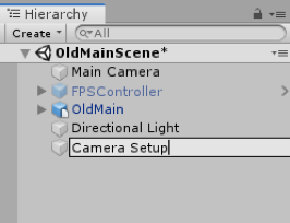
Finally, drag the “Main Camera” object onto “Camera Setups” so that it becomes a child of it. This is how things should now look in the Hierarchy Window:
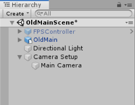
Now we have to place the camera in a good starting position for our camera flight. We want the camera flight to start a little bit away from the Walker building, and then move towards it before transitioning into an orbit around the building. So move the Scene view to a perspective similar to that shown in the screenshot below. First, set the position of both the parent object “Camera Setup” and its child object “Main Camera” to 0,0,0. Then manipulate the location and rotation of only the parent object “Camera Setup” to move both objects at the same time to a location you desire. If you did everything correctly, the Main Camera Position and Rotation values will all still be zero as in the screenshot below because they are measured relative to the parent object.
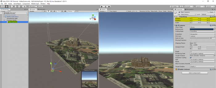
Creating the Camera Animation
Creating the Camera Animation
Now we are going to create the camera flight path. First, we are going to create a new Animation entity for the camera flight in our project Assets and link it to our Camera Setup object. Then we are going to set intermediate positions for the camera along the desired flight path. Unity will automatically interpolate between these positions so that we get a smooth flight path.
Create a new folder called “Camera Animation” under the Assets folder. Open this folder, right-click on an empty space within the folder, select Create -> Animation. This creates a new animation clip entity. Let's call it “CameraFlight”.
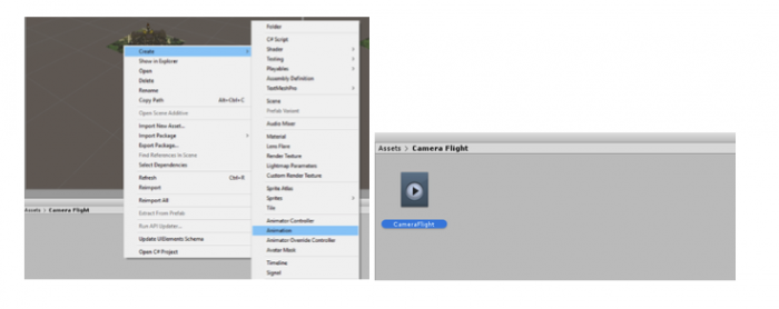
Connect the CameraFlight animation to our Camera Setup object by selecting Camera Setup in the Hierarchy Window and then dragging the CameraFlight animation from the Assets Window to the free area with the “Add Component” button in the Inspector Window (you have seen examples of adding elements and components to GameObjects using this method in previous videos). After doing so, the Inspector Window should show the newly attached Animator component as in the screenshot below. In addition, a new Animator object called "Camera Setup.controller" will automatically appear in the Assets window.
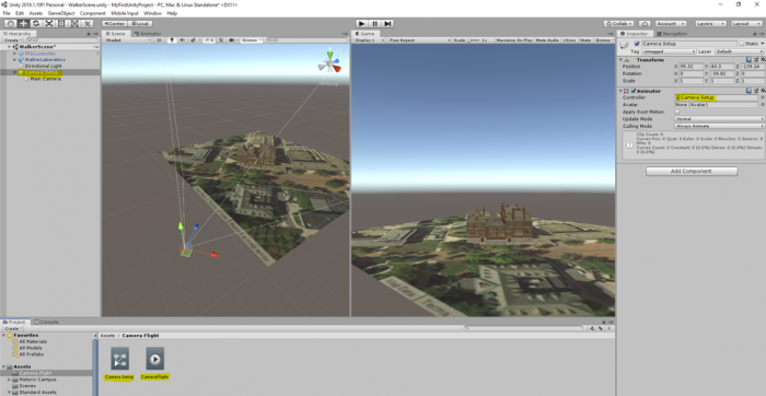
During the next steps, make sure that "Camera Setup" remains selected in the Hierarchy Window. Go to "Window -> Animation -> Animation” in the menu bar to open the Animation Window which is the main tool for creating an animation.
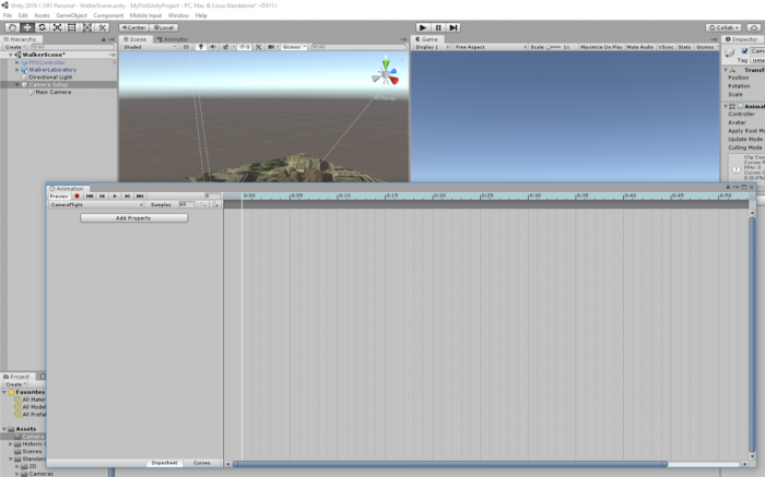
Let us first make a few adjustments to the Animation Window to make things easier. At the top right, you can see the timeline for the animation. 1:00 means one second into the animation. You need to have the mouse cursor in the lower right part of the window and then turn the mouse wheel to adjust the timeline. Our animation should probably be around 1 minute long. So set it up so that the timeline goes until at least 60:00 seconds (= 1 minute). It is a good idea to make the Animation Window as wide as possible.
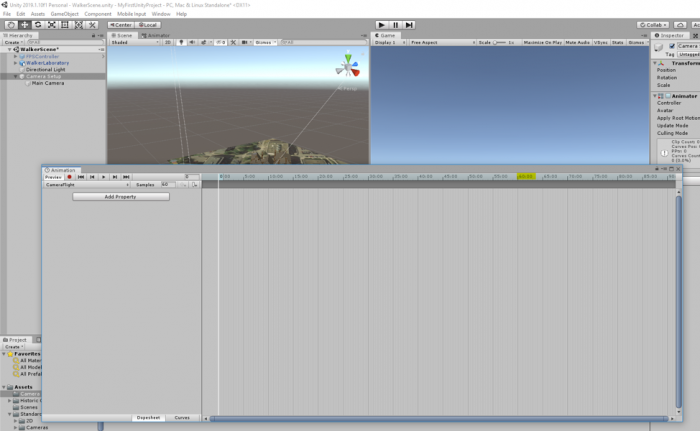
Now let’s clearly specify which properties we want to animate in our animation, namely the position and rotation values of our Camera Setup object. You will have to use the "Add Property" button twice to add the Position and Rotation, respectively. Press “Add Property”, then unfold the “Transform” entry, and use the + button to add Position and after that Rotation to the list. The result should look like in the second image below:
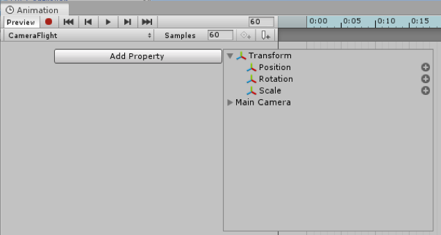
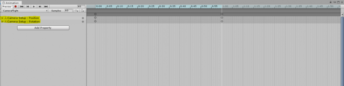
The diamond symbols below the timeline are the keyframes, which we will use to define intermediate positions and orientations for the camera along the flight path. As you can see, Unity has automatically created two keyframes, a start frame at 0:00 and another one at 1:00. You can select a keyframe by clicking on the upper diamond (the one that is in the darker gray bar, the selected keyframe is shown in blue) and you can drag it to the left or right to change the time when it will occur. You can delete a key frame by right-clicking the diamond and then selecting "Delete Keys". That's what we want to do here so that we end up with only the start keyframe like in the figure below:
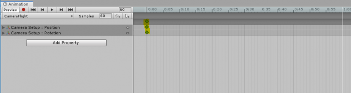
The red record button on the top left determines whether changes will be recorded for the position in the animation where the vertical white bar is located which will result in a new keyframe being added at that position. When record is on, the position and rotation properties of the Camera Setup will turn red. Do a left-click at 10:00 in the timeline to move the white vertical bar to that position.
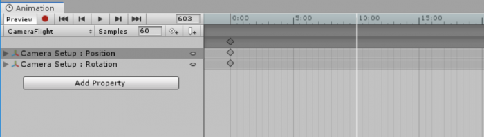
Now let's create a second keyframe at 10:00 and record it. Press on the record button (the red circle in the animation window) and then use the move or rotate tools to change the position and rotation of the Camera Setup GameObject in the scene. Note that all the changes you are making to the position and rotation of the camera will happen in 10 seconds, as this is the limit we have specified for this frame. Once you are happy with the changes, stop the recording.
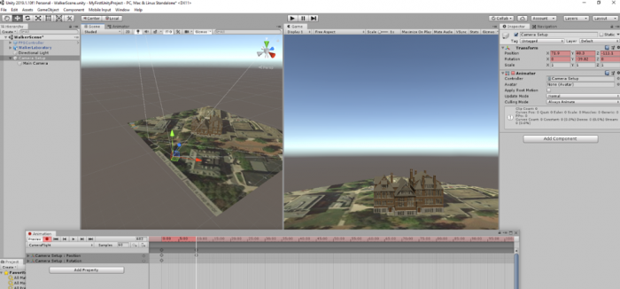
Repeat the same process to add another keyframe every 10 seconds and make another recording.
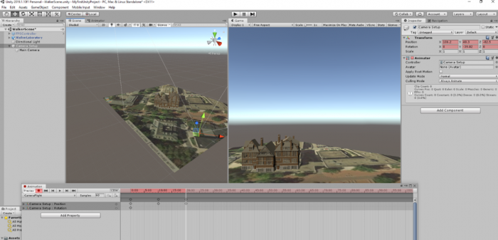
You can use the perspective gizmo at the top right of the Scene Window to quickly switch between the top-down and side view of the view, which can be very helpful here.
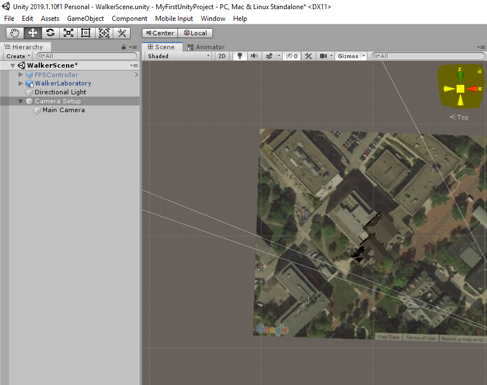
You can now click the Play button  in the Animation window (not the main Play button at the top!) and Unity will now show you the animation between the first and second keyframe in the Game Window. Press the button again to stop the animation.
Before continuing, make again sure that you have Camera Setup selected in the Hierarchy and that recording in the Animation window is turned on (record button with a red dot is highlighted).
Now continue with this to build a camera animation of 60 seconds with 7 keyframes in total, one every 10 seconds. For each of the keyframes move the view to the next corner of Old Main. The last keyframe at 60:00 should be roughly identical to the very first one, meaning you should move "Camera Setup" away from the building again.
The final animation should look similar to the one in this 360° video [152] (producing such a 360° video from the animation is described later in this lesson). Creating such animation can be a bit tricky at first but you will get used to it quickly. Don't worry if the orbit around the building isn't perfect. This is ok because we are only using very few intermediate keyframes here. You can try to improve on this in your homework assignment. If something goes completely wrong, you can always delete the last few keyframes using "right-click -> Delete Keys". Here are a few additional hints that you may find helpful:
- Don’t forget to save your project after each successful step and remember that you can take steps back using CTRL+Z. It's also recommended to make backup copies of the entire project folder after each major step. This allows for going back to an earlier version if something goes completely wrong.
- Also, remember that you can shift keyframes back and forth in time by dragging them along the dark gray bar.
- If you just want to preview parts of your animation instead of everything from beginning to end, you can place the white vertical bar by clicking into the timeline and then the preview with will start at that position.
- If the camera gets very close to the building and the front side polygons of the building are getting clipped, you can try to fix this by setting the "Clipping Planes -> Near" property of the "Main Camera" object (child of "Camera Setup") from 0.3 to 0.01 in the Inspector Window.
Camera Flight Complete (05:27) (A complete instruction video of what we just did) This video is not narrated.
Running the Project
Running the Project
Once you are done with your animation, you can close the Animation window, maximize the Game Window, and look at your camera flight in full size. Just press the main Play button at the top or CTRL+P.
Check out whether you are happy with your camera flight as it appears in the Game Window. If not, you can revisit it by selecting Camera Setups and opening the Animation window again under “Windows -> Animation”.
You can now go ahead and build a stand-alone Windows application as explained in Lesson 7. Our next goal will be a little different. We want to be able to see the camera flight in 3D and be able to actually look around. One option would be to turn this project into a VR application, for instance for the Oculus Rift or HTC Vive. But since most likely not many of us have access to an expensive VR device, what we are going to do instead is to use the Google Cardboard for our “VR application”. The approach we are taking for this is to record a 360° movie of our animation, make it available on YouTube, and use YouTube’s Cardboard support available on most smartphones to turn the video into a VR application.
Unity-based VR Applications for Mobile Devices
Unity-based VR Applications for Mobile Devices
You already learned about building stand-alone 3D applications for Windows with Unity. Creating stand-alone software that allows for experiencing the application in real 3D with the help of a VR head-mounted display connected to the Windows computer is not much different. While you probably won't be able to try this out yourself (unless you own a device such as the Oculus Rift or HTC Vive), Unity VR Overview [153] provides a good overview on VR support in Unity and building VR stand-alone applications. Additional information can be found at Unity Learn [154].
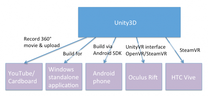
Similarly, you can build stand-alone applications for mobile platforms such as Android or iOS and even have the built app directly pushed to your mobile device. This requires additional software to be installed on your computer, such as the Android SDK if you are building for an Android phone or tablet. However, despite a lot of progress in hardware and, in particular, graphics performance on modern mobile devices, smoothly rendering 3D scenes in high quality on a mobile phone, for instance, can still be problematic. This is particularly true if the scene needs to be rendered for the left and right eye separately to support a VR device like the Google Cardboard. We will, therefore, take a different approach in the following walkthrough and instead use Unity to produce a 360° video that can be shared, for instance via YouTube, and then be experienced in real 3D on pretty much any(!) smartphone with the Google Cardboard. While this approach is limited in that no interaction between the user and the objects in the scene is possible, advantages of the approach in addition to being less dependent on high-performance hardware are that we do not need to produce different builds for different mobile platforms and no additional software needs to be installed. If you, however, are interested in exploring how to build stand-alone (VR) applications for Android devices, the Android environment setup instructions [155] and the video below are good starting points.
Video: Live Training 10 Mar 2014 - Mobile Development (1:08:46)
Hello everybody and welcome to another one of our live trainings on Unity. My name is Mike Geig and today we will be talking about mobile development. If you are on our Facebook page, then you've seen a version of this picture before. But I decided to spruce it up with an American flag cape because, what can I say, I'm a patriot. So today we are going to be talking about mobile development and we are going to be basically targeting kind of how we start, right. You're going to notice that a lot of a lot of programming for games for mobile is is pretty much exactly the same for for web or for desktop. So I don't really need to get into a lot of depth there because really not a lot of depth is needed. When you're thinking about mobile platforms there's really only two things you need to keep in mind that's different from say desktop or anything else, and that is A) How are you going to control the game? because input is very limited on mobile device and B) What kind of screen real estate are your going to have and what kind of hardware power are you going to have? because you know we will know that mobile devices can't run as intensive games as anything else. We've got a lot of people participating in chat today so obviously I'll be moving along with the lesson and trying to keep up trying to keep up with the chat. So if you hear me pausing for bit it's because I'm reading chat and trying to answer your questions. I haven't said it in a while but, you know, if you have questions during the lessons obviously post your questions in chat and you know I'll try to answer them. Okay so yes I hope you all enjoy my my my super-awesome picture there, okay. So someone had mentioned before something about data persistence. That was last week. This week is mobile development. I changed the title but some people are still seeing it say data persistence. So today is mobile. Yeah, so so there you go.
Okay so before we begin, like always, if you have any questions, comments, concerns, anything like that, you can follow us on Twitter @unity3d @mikegeig, which is me, @willgoldstone and @theantranch. We love talking to you on Twitter and yeah so if you're here, you have any questions, or just want to talk, twitter, twitter it up. For those of you who watched last week, I was in London on a mac and trying to figure that whole thing out. Today I am back in my house and so I'm back on my computer, windows, which I'm much more familiar with and I have my mechanical keyboard. So I know some of you last week we're really missing the mechanical keyboard, this week its back so if you don't like the mechanical keyboard, sorry, its back. But yeah. Oh someone asked in chat if I work for Unity. I do in fact work for Unity. I am a screencaster/trainer for Unity. So, hello.
Okay, so let's let's start talking. So the first thing we're going to do, when when when doing any mobile development in Unity, is we need to set up our mobile development environment. By default, Unity integrates with the SDKs for whatever mobile device we want, but we have to actually have those. So some of the steps obviously I'm not going to talk about right now, is that you need to download the SDK. So if you're using Android, you need to download the Android SDK. And the documentation on Android is on Android's website on how to do that. You download and install the Android SDK and update it and do all that stuff. And if you're on iOS, you need to download Xcode and all the the apple goodness stuff, alright. So those two things have absolutely nothing to do with Unity so I'm not really going to talk about them, but they have to be done.
Let's see here question, Can you use the Android Nexus 7? Absolutely, yeah you can pretty much do a lot of Android and iOS and and whatnot. And there are some limitations as to which stuff Unity will run on. but for the most part we cover pretty much all devices or most devices, and more and more every day. So assuming we've already downloaded and installed Android or iOS, we need to basically tell unity about it. Now with iOS, Unity is automatically going to know about it. So you just download your Xcode, you know you set that all up in Unity, we'll know where it is because it is always in the same spot. You will need an iOS developers license. I'm not an iOS developer at al. I don't own a Mac. But I believe it's a hundred dollar license fee through them, though I'm not entirely certain. And you need to log into that service before you can do iOS dev. The Android SDK is free, though it's it's it's a little complicated to get set up, so obviously consult the documentation because it's so it's a little bit different. Now Android, since you can install the Android SDK pretty much anywhere, will not automatically be recognized by Unity, so you need to tell Unity where it is. And to do that, you're just going to come into edit, and then Preferences, and click this external tools option. Right here you're going to see Android SDK location and you just need to tell it where you saved that information. And from then on out it will it will say, hey ok so we know where your SDK is, and all that is working fine.
Ooh, chats crazy. Will I be at GDC? I will, in fact, be at GDC, so if you're going to GDC message me, we'll hang out. Let's see here. Some people are talking about my mechanical keyboard, okay Are you going to cover using different quality assets like images for a 2-d game? We'll talk a little bit about resolutions and images near the end of this um let's see here let's see here I know I mean someone says let him get started I hope I'm getting just destroyed by questions right now maybe we'll do a second mobile session that's just QA because you all seem to have a lot of questions let's see here oh we're going to avoid platform specifics today we're not going to talk about plots platform specifics just to do can you use the free version of unity or do you need the iOS android windows add-ons I believe there's a free version of the iOS Android add-ons there's like a free version of foreign dollar version and then like the more expensive pro version I think man it's been forever since I looked at licensing you have to go to unity site and check it out I honestly cannot remember to see I wouldn't yeah it so someone said to do Android 2.2 a great two point three in greater which is which is right let's see here okay so yes a lot of basic questions what is an SDK is one of the questions that just popped up in an SDK is a software development kit it's basically a whole bunch of ways for us to interface with some hardware or something else right so an Android SDK allows us to write applications for Android but anyway okay so at this point we're going to pretend like we've installed Xcode or we've downloaded Android and that's all that's all good to go so at that point our our editor is kind of is ready to go but there's a couple more steps that you really want to do the first thing you want to do is come into file and build settings and ensure that you are currently set up for whatever platform you're building for so I'm building for Android you're going to see the things we do today it won't matter if you're on Android or iOS so if you're following along or if you're watching this later in the archive and you want to follow along it really doesn't matter if you're on Android or iOS it's really irrelevant because all the stuff we're going to do works for both and I believe it all works for the Windows Phone 8 as well but I've not personally tested that but I'm pretty sure it's the same so yeah so anyway if you're sailing on PC Mac or Linux standalone you'll just want to select your platform and click this switch platform button you can see that I'm already on the Android platform because I have this little unity icon here which means I'm currently building for Android that's the platform it's currently on and we don't really need to mess with any of these settings right now I've also already added my main scene here but we're not going to really worry about that right now so we need to you know obviously switch to the appropriate platform another thing I want to do I generally always do is I try to set up my my aspect ratio so in this case I'm in 16 by 10 landscape you're going to see they're going to have some different options alright because I switch my platform to mobile so I don't see the standard options that I normally see I see a whole bunch of different options in this case I'm choosing 16 by 10 landscape because my test device happens to be a nexus 10 tablet if you know depending on on what device you're using you'll want to pick an appropriate aspect ratio for that okay um let's see here oh geez alright so a lot of questions in chat craziness um anyway so I'm gonna kind of skip a lot of these questions because I just can't get to them right now I'd really like to get started alright so our editor is in the appropriate build mode in my case it's Android I've set up my game to have the appropriate aspect ratio so now the first thing I want to do is I want to talk about touch input there's basically predominantly two ways to interface with a mobile device and that is a multi-touch screen which most devices nowadays have a multi-touch screen and also a in the accelerometer right and iOS devices also have a gyroscope which functions kind of similar to an accelerometer we're going to ignore the gyroscope for today because we can do pretty much the same stuff with the accelerometer and since Android devices generally don't have a gyroscope it would be something that applies to both so as I said I'm trying to do things that apply to both so I'm skipping the gyroscope but the input device if you're reading unities documentation you need to use mobile documentation is a little bit older it talks about how iOS only allows five touches and Android allows somewhere between two and five and it has been my experience now that both iOS and Android allow well over ten touches or five touches obviously how many touches depends entirely on the device but but that number is a little bit bit bit low so what we can do is we can we can read in whatever is touching the screen and generally our devices are touch capacitive screens which means it has to be something like your hand touching it something that will will conduct a current and so and that's how the device screen knows where are our hands our fingers or whatever our stylus pens or whatever are touching the screen now since our screens are flat we are dealing specifically in screen coordinates right so obviously we don't have an x y&z; axis with our mobile devices as far as touching goes because the screen is basically a flat canvas and so I have this little amazing infographic here that basically talks about how the position works on on mobile screens all right and so basically the lower left-hand corner is zero zero all right is is the origin and basically it goes from zero to the screens height upwards and zero to the screens with right words and so that is that is our screen coordinates now this doesn't matter if we're in landscape mode or portrait mode basically the lower left will always be zero zero and height will always be up in width will always be over so if you're in portrait mode the system updates to the lower left hand corner and if you're if you flip to landscape mode again the system updates so yeah basically wherever we touch the screen it's going to be a 2d coordinate whereas going to have an x and y component and it's going to be some x position comma some Y position yeah someone said in chat don't forget the z axis is towards the user not when we're talking about screen coordinates there is no towards the user because this is flat yeah someone also mentioned that I thought as ears are started at the top left in some instances zero zero is the top left but in this instance on zero zero is the bottom left so that's just that's just how this is handled and so we can like so if we're talking about the GUI system the top left is zero zero but we're talking about mobile touchscreen coordinates and it's the it's the lower left is our zero zero so okay so let's let's talk about touches so basically touches are stored in an array because we can have more than one touch right and so we can't just be like hey what's our one touch we need a collection of touches and we access all of those through the the input class just like we do any other form of input because you know multi-touch screen is also just input so basically what we're what we need to do is we need to access the input class and we need to find this information about our touches we do that all through scripts so what I'm going to do is I'm going to go ahead and just create a script we create a c-sharp script which I'm just going to call touch script oh one more thing I want to talk about today real quick I am using the unity remote application on my Android device so I'm doing that specifically so you guys can see what I'm doing if you think about it normally the best way to get good performance good reliability is to build my my project send it to my android tablet and test it on my android tablet right however you won't be able to see that you're all watching my computer screen and I don't have another camera to show you the contents of my tablet so I have installed the unity remote on my tablet if you and you can find the unity remote from the Android store and from the iOS store it's just called unity remote it's free if you find that you're being charged for it you're getting the wrong one unity remote is free and basically what that's going to allow me to do is it's going to allow me to use by my tablet as an input device into the editor so I can test my mobile application in the editor now the reason I mean that works but it can be a little buggy sometimes it doesn't work and if it forces or imposes specific specific orientations on me and stuff like that so it's not as fluid as just basically deploying to my device and testing it that way so just keep that in mind what I'm doing is I'm using the unity real remote you're more than welcome to do that your new remote is fantastic it allows me to test any editor but what I want to do real testing I deployed in my device alright so just just keep that in mind and yet someone is said in chat it is a bit laggy the unity remote is so now that's effectively what I'm using so you're going to basically see that and so I'm going to go ahead and just put this touch grip on my main camera you can see here I just have a scene this just got a cube a direction light and a main camera so in case you're wondering what I already have in here nothing really I'm gonna go ahead and open this touch script there we go and I'll zoom in the problem is always seeing stuff Oh chats going crazy let's see here that's a lot of language I don't understand because that's not English ah let's see here that's a lot of not English I don't know what anyone's talking about everyone's talking in a different language okay let let's try to limit chat to being specifically about the topic right now and preferably at least for me to be in English unless you don't speak English because well if you don't speak English you're not going to be getting a whole lot of this life session anyway but it's a little distracting so alright so the first thing we want to do is we want to necessarily want to kind of get the touch information and like I said before the touch is stored in an array and that array is called touches so I can access input dot touches and this is an array and I could just be like touch a subzero touch uh someone whatever right so there's this array of touches all right a lot of times I would want to iterate through this array of touches and that's actually what we're going to do here in a second but before we do that I want to talk about an individual touch a touch is a class and so what I want to say is something along the lines of touch I don't know my touch equals and let's say I want to get the very first touch right I just want to put my finger down and get that one finger position directly on the screen I would do inputs not get touch and this will give me back an index member from the array I want zero to give me the first touch I've just been informed that the language people are speaking in chat is Turkish so okay hello I did not know that thanks Christina appreciate it okay and so what this is going to do is this is going to give me back the first touch in the array which I will store is here is my touch from the touch struct and touch is fact is instructed not a class which for our intents and purposes right now really doesn't matter alright so just keep that in mind and so this touch has a lot of a lot of stuff that is very useful to us alright so let's consider I'm just gonna go my touch I'm just going to hit dot and let's look through the things that touch has right so the first things first is Dutch has a touch has a delta position a delta position tells me how much my finger or whatever device is touching the screen has moved since the last time it was looked at since the last update all right Delta time is the amount of time since the last update which most of the time Delta time is the same as time that time unless you're pulling for your input somewhere else right but usually Delta time will be the same as time that time finger ID tells me which finger it is so if I if I put my my index finger down on the screen my finger ID will be 0 if I while holding that on the screen I touch it with another finger my that finger ID will be 1 and so on and so forth so finger ID is the index of the specific touch then we have phase which is what phase that touches in and the phases are begin moving stationary and ended so begin is the first frame of a touch stationary as if the touch isn't moving moved is the the touch did move and in means I pick my finger off the screen and then there's a fifth one called cancelled and cancelled it's only if there's some air and it can't read the input the position is its position on the screen raw position I actually don't know what that is raw position I don't know maybe we'll look at this here in a second how would you use position I've no idea what raw position is so yeah maybe raw position is the screen position without menus and stuff like that so I know in Android it's got that little menu bar at the bottom and so it doesn't count that as part of its position so maybe raw position is without that not entirely certain tab count is how many times you're tapping your finger and it keeps it keeps track of that in case we're doing quick taps and then to string just kind of outputs the class because that's something that's inherited so those are all the pieces of a touch alright and I can just get one touch which we're actually going to look at doing here in a little bit and I can do stuff with that alright uh but for now I don't I don't want to mess around with individual touches what I'm going to do is I want to help put to the screen information about a bunch of touches so once I get here I am just reading through chat now let's see here okay nothing that is really pertinent again please try to keep chat not relevant to relevant to what we're doing here so here's a question how does finger ID work if you put down one finger and then put down another remove the first finger while holding the second one so basically if I put down one finger it's gonna have an ID of zero but put down to the second fingers can have an ID of one if I pick up my first finger my second finger will still have an ID of 1 and zero will be freed up so it's not like it switches or anything that keeps track of the fingers while the fingers are touching right and I'll actually here in just a second we're going to build we're going to build a basically a little demo here that's going to show you exactly how it works and so that's what we're actually let's do that right now and so I don't really care about update right here so what I'm going to do is I'm going to do an ongoing method there's that kind of keyboard for you guys and so what I want to do is I want to iterate through my collection of touches and I want to output some information to the screen about those touches all right so I'm just gonna do a quick foreach loop and I'm gonna say for each touch a touch in input dot touches oops I don't know why I did acceleration input that touches so this will go through all of the touches in this touch array and I'm just going to build a message here so I'm going to do a string message and I'm gonna say message plus equals and so over the base I'm going to do is can can't need some information so ID + touch dot finger ID uh plus this part gets a little long-winded and let me see here let me just copy this because we're basically gonna be doing this a bunch so that's our ID and then we're going to say hey what phase is it on and we'll do touch dot phase and the phase needs to be two string and then we'll say touch dot after phase let's go ahead and do tap count which again will be touched dot dot tap count and then we'll do after tap count let's do say position let's do position X position X and that will be touch dot position X and let's do oops let's do position Y which will be position dot y all right um and then let's do we're going to need to do a little bit of an offset so these don't all overlap each other so I'm going to intim equals touch finger ID and then I'm going to say GUI label and that label will be positioned at new rectangle and the new rectangle is going to be 0 plus 130 times num this will allow us just to offset them across the screen you'll see in a second what this is doing zero 120 and 100 and then message which is the message during we just created alright so what this is going to do is it's going to go through each touch I have on the screen and it's going to output this information to a GUI label this part here the num just allows me to offset so the the first finger will be at 0 the second will be at 130 the third will be at 260 and so on and so forth so we can have them all kind of cross the screen there all right so let's go ahead and save that and let's go back into unity and let me wake my tablet up here and hopefully the the unity remote picks it up the very first time so I'm opening up my unity remote I'm going to hit play the unity remote did pick it up so now I'm going to touch the screen with one finger and I see ID 0 phase the stationary tap count is 1 position X in position Y and as I move this you'll see it flips between stationary moved it's updating obviously much faster than my finger is moving so we supposedly see stationary but we can see exactly where I'm touching or if I pick it up goes away put it down it comes back if I put a second finger down there was our second finger third fourth fifth six seventh women let's try this again oops I lost my my tablet there we go ok so let's try this 1 2 3 4 1 2 3 4 oh it fell out of its case see what I was saying about the the remote kind of being a little weird anyway you get the idea if I would actually deployed this to my device it would be much more accurate but since I'm running it from the Unity remote it can can get a little bit iffy there's well now I kind of lost track cuz it just goes off the screen anyway so I got eight at least so they're real but basically using this I can just see all sorts of information about a bunch of different touches up and basically oh it looks like 9 is the most my device will allow me because down here my console I see out of free touches so that must mean that that after I did eight that was that was it so eight must be the maximum on this particular device because I started getting the error out of three touches so yeah so basically you know this is just a real simple ways that we can see kind of how the different parts changed now watch I'm going to tap my finger and it kind of flashes there let's see if I but it does say tap count to real quick because it means I'd tap my finger twice oh there we go I got up to tap count four so basically I'm to hit hit real fast I got to tap count eight so you can see that we can let allow unity to recognize different tap counts now another thing about the unity documentation if you go read the unity mobile documentation it's going to say that Android does not support tap count and iOS does it didn't a long time ago but now obviously I'm using an Android device and it supports tap count just fine so tap count does work so if you're reading that on there don't think you know that that it doesn't do that anymore um okay so now I see the people are talking about c-sharp versus JavaScript okay apparently no one wants to listen to me and just keep the talk about mobile development but let me see if there's anything that I should be answering in here oh let's see here people are just how many fingers do I have I have ten fingers which is unfortunate that I didn't have ten touches that I can utilize um I oh I put the script just on my camera it doesn't really matter where you put it um it's an ongoing function so it'll run from anywhere oh let's see here now let's see here yeah it's on the camera yeah yes this will be archived all my videos are archived for anyone wondering let's see here alright so okay for those who said that it says stationary all the time it actually flips between stationary move but just really really quickly because remember this this is running well how many frames a second this is run in like 300 frames a second and you don't really know how fast the update method is actually being called but um it runs fast so obviously do something moving that fast my finger doesn't seem like it's moving at all so just keep that in mind okay so that's a real simple just like hey let's output stuff to the screen oh and here's another question just touch class or well touch another class but the question is touch class already in general library or do you need a special input it is already it's part of unity engine so you do not need to call it input or anything like that yeah so okay so now let's let's do something a little bit more interesting I'm going to go ahead and turn that touch script off and let's move this cube with our finger so what I'm going to do is I'm going to create a c-sharp script which I'll just call move script and let's go ahead and just click and drag that onto the cube there we go and let's open it up alright so basically what we want to do is we want to say hey if there is a touch we want to move this cube so let's just come down in here and I'm going to say if input god that's a touch count equals one means there's exactly one touch on the screen so what this means is if I put two fingers on the screen I won't be able to move the cube and if I obviously if I'm not touching the screen I again won't be able to move the cube I have to have exactly one finger on the screen or a stylus or whatever which is one touch read all right so my touch count equals one then what I'm going to do is I'm going to say transform dot translate and what I want to do is I'm going to say input dot touches this time I'm just going to use the array on the next time you're going to see me get a reference to up using touch so got Delta position so basically how much has the the finger changed over the course in frame X and in this case we're going to dampen it a little bit by multiplying it by 0.25 that's just going to make it not go SuperDuper fast and then in the y-direction I'm going to do the same I don't know why that just said space right there in the y-direction I'm going to do inputs and actually I'm just gonna copy this going on your input that touches Delta position Y and then I'm not going to move in the Z Direction 0 in the Z Direction okay obviously I'm stacking this up because otherwise wouldn't fit on the screen because I'm zoomed in so far so basically what we're saying is if we have one touch that what I'm going to do is I'm going to translate this cube by the Delta position of X by how much X is moving all right and that's going to allow us to touch the screen with our finger and move things around so let us come back here to unity and I'm gonna hit play and I'm just going to touch my screen and you can see that I'm able to move the cube around just by touching my my tablet so the cube moves around now you are gonna notice that the the cube does not move exactly with the finger right so my fingers move in a little bit the cube is moving more just because it's it's I'm using a perspective camera it's not a one-to-one ratio so you know the cube is not I'm gonna move in the cube obviously but it's not quite the same alright so what I'm gonna but I mean it works right that's that's specifically what I wanted to show you how to how to do but let's do this let's say I want the cube to move exactly where my fingers touching right like by using some percentage of the screen width or height now that is certainly doable but it's not really doable the way we have it now so what I'm going to do is this is I'm going to this part it's just for aesthetics but I'm going to change my camera to be orthographic okay again that I don't need to do that that's for aesthetics so that it it looks more more pleasing so I'm going to set this to orthographic and then I'm going to modify move script so I'm going to come back into my move script here and in this case we are going to to make some changes so I'm going to go ahead and get rid of this line of code and I'm gonna instead say touch touch equals input get touch I just told you I'd show you the other way so I'm not just referencing it all the time and so what I'm going to do is I'm going to create a float X&Y; and I'm going to set that up to a percentage of the screen width and height based on the position of my touch now I'm just going to do the math here real quick just know that that I determine this ahead of time I determined that the left bound of my screen was negative 7.5 the right bound was positive 7.5 the upper bound was 4.5 in the lower bound was negative 4.5 so I've already calculated this out okay so if you're wondering where I'm getting these numbers I already just move the cube around and figured out where the bounds of my screen were so I'm going to say float x equals negative 7 point 5 plus 15 times touch dot position dot X divided by screen got with okay so basically touch top position dot X divided my screen up with will give me some percentage of the way across the screen my finger is then I multiply that by 15 and then I add it to negative seven point five so that if my touches all the way to the left it'll be zero zero times 15 is zero in a row be at negative seven point five which is my left bound if my fingers all the way to the right this will be 1 1 times 15 is 15 plus negative seven point five will leave me with seven point five which is the right side of my screen so that's effectively what we're doing here and the same was going to go for y so I'm just going to go ahead and copy paste and I'm going to replace X with y I'll change this thing I get four point five I'll change this to nine and I'll change this to touch position dot Y and screen got height okay there we go okay and so that is going to tell me the X&Y; position in this in the game that I that correlates the finger position on the screen all right and so then all I really need to do is I need to set my transform to that so I'm going to say transform got position equals new vector3 and I'll position it at X Y and 0 again we're not using the z-axis Oh chats going crazy today all right let's see here oh by the way yeah so someone mentioned this or I see some people talking about it I'm using the GUI system just to show you guys some stuff don't use the GUI system with mobile devices hopefully we'll have a chance here sometime to talk about efficiencies a little bit and the GUI system as it stands right now that our current GUI system is just not efficient enough for mobile devices so don't use on GUI with mobile devices I only did it to kind of demonstrate that for you guys so you won't want to do that all right and so this is all saved so let's come back to unity and let's see what happens so I'm gonna go I'm gonna have an error what did I forget to do something about a float casting all right around my F's that was a test you all failed you were supposed to point it out some of you might have I haven't been looking at chat all right and so let's see here I'll go ahead and hit play and so now you'll see that I'll touch the screen with my finger and I will move this around all right yeah and if someone pointed out this works for all screen resolutions right specifically because I'm doing position X divided by screened out width so it really doesn't matter what the resolution is this it'll work for anything so yeah um interestingly enough the way I've set this up means I can just tap anywhere and the cube will go to where my finger is touching all right because now it just correlates to where my finger it so I say I want to touch the upper right hand corner just tap the upper right hand corner and there's my cube lower right hand corner or that was a lower left hand corner lower right hand corner upper left hand corner so on and so forth direct middle whatever and so this allows the the cube to move with my with my finger so once the person said here let's see you said that the left bottom corner was zero zero increasing X to the right increasing one at the top how can there be negative numbers if there's no space the left bottom from zero zero because the negative numbers are in my game right look at my game so if I pick my cube my cube is at zero zero right now let me go into 2d if I want to move my cube to the upper left-hand corner you'll see it's at roughly negative point five four point five right to the right so I'm not talking about screen coordinates I'm converting screen coordinates to world coordinates that's what that is anyway okay so that's what's going on there okay so you can see that we can basically use input uh for all sorts of stuff all right so in actually right now someone mentioned that I'm using Delta input I'm not using your Delta position I'm not using Delta position I'm just using position right I don't want the change in position I'm with the actual position so anyway so at this point you can see that we can use these touches for all sorts of stuff I can move stuff around the screen I can select items I can shoot lasers I can you know whatever I want to do so yeah touch the touch input is really cool so now let's take a second let's talk about the accelerometer all right the accelerometer is our second form of input and the accelerometer will basically tell me which direction the tablet is kind of leaning all right and and it's actually really really really simple basically now I have a graphic for it basically we have three coordinates with the accelerometer because the accelerometer tells us the device's physical orientation in real life okay and just like in unity the three axes line up in such that Y is up and down X is left and right and Z is in and out however in this case a positive Z is towards us a negative Z is away from us but in unity positive Z is away from us and negative z is towards us so a lot of times you're going to see us use negative Z to get unity to map to our device all right and so and what we can see is X is up and down Z's in and out or I'm sorry Y is up and down Z's in and out X is left and right and that works regardless of what orientation we're in okay so if I flip my device from portrait to landscape unity will automatically update that stuff okay so we don't really need to worry about the orientation of our devices now that being said let me show you how to choose that stuff so again I'm going to be using the unity remote and the unity remote handles axes a little bit differently it forces an orientation on me or I don't really get to choose because that's just for testing right and so but assuming I'm deploying my device I can choose what orientations I want my device to be in so I can come to edit project settings player and I can look over here and see my Android settings which my Android my iOS settings are actually fairly simple fairly similar but I can see that by default my device will be in landscape left now this obviously only is for when I actually deploy it not for when I am using my accelerometer I can also say hey I want it to be portrait I can make it portrait upside down landscape right right I get to choose what orientation my device is in now if you want the user to be able to use the game play the game in any orientation or specific orientations like say I want to enable portrait mode and landscape left I want them to be able to rotate their phone and play it in different orientations I can choose auto rotation and once I do that I can actually say okay I want to allow portrait I don't want portrait upside down I don't want portrait right but I do want landscape left or I'm sorry Lansing right but I do want landscape left left so I have some choices here where I can I can also hide the status bar and I can do all sorts of stuff but basically you know this comes in play with our accelerometer however again just to emphasize that I am using the unity remote so don't really get a choice right now because the unity Romo is just going to enforce I can change the Union Rose orientation by changing my game orientation in the game view my aspect ratio but otherwise it just kind of fixes in because it's it's just for simple testing um I don't see your man everyone's still talking about the GUI come on guys getting that distracting here trying to trying to see all of the different questions and not questions related to GUI let's see here so when I have multiple sorry China's just going too fast I can't I can't quite read it quickly when I have multiple elements I want to drag how would detect touch on each of them raycasting yeah so the question is you know if you're touching the screen how do you to tell what you're touching on and you can just raycast it's the same as clicking on it right you click and then you should read cast from the camera to your mouth position in this case we can touch and shoot a ray cast from the screen or from the camera into our finger position so that all certainly works all right so anyway okay so more chat about regular stuff let's let's talk come back to talking about accelerometer now so I showed you or just talk real quick about how you know we have we can change our orientations and things like that so let's look at actually creating accelerometer script and so I'm going to create new c-sharp script which I'll just call excel script and basically it's real simple so our accelerometer will go between negative 1 and 1 and all three axes it's just like input dot get axes vertical horizontal rate we're just doing input that acceleration right so it's just a vector 3 that has has this acceleration information it's actually really really simple to use one of the things you're going to notice so I'm just going to tell you right now is that you can really only utilize two of the of the axes at any given time right so you have three axes for your accelerometer but if you think about it I can like say I have my device straight up and down in portrait mode but I can really only utilize the X and the z-axis and you might be thinking what can access the y-axis because gravity is pulling the y-axis down like constantly and so it's just going to be a solid negative one right so it's really hard to utilize all three axes of the accelerometer at any given time because one of those is always going to be pulled by gravity right so what we want is we want to situational gravity's partially pulling on the accelerometers so that we can utilize them but one is always going to be heavily pulled it's really you know hard to orient it orient a device so that doesn't happen but okay so let's talk about actually working with accelerometer here so I'm going to go ahead and just remove this default crud and what I want to do and it's actually really simple is I'm just going to transform this q or translate this cube based on accelerometer so I'm just going to say transform that translate you not transform that transforms that doesn't make any sense transform that translate and how I'm going to translate is I'm going to be I'm going to say I want my cube to move left and right as I tilt my device along the x-axis so basically if I turn it like a steering wheel alright that's me moving it on the x-axis alright because I'm if I'm rotating it about the Z I'm moving it about the X I know that's kind of confusing but just imagine in your head like a steering wheel and if I if I turn if I make a left-hand turn with my steering wheel I'm going to the negative x-axis if I make a right-hand turn going the positive x-axis and so what I want to say is going to say input dot acceleration got X okay and then I'm gonna say x times Delta alright so that doesn't again move really really fast right so that will move me along the x-axis I'm also going to move zero along the y-axis and then I'm going to just pop down a line here and for my z-axis um I can say input dot acceleration Dunsey x time.deltatime oops times that tell the time and this works but if you remember what I said before with the device positive X's towards me but by default unity positive X is away from me so to make this work the way I want I have to make that say negative input that acceleration o dot Z there we go and I have that dot in there or else it will not work okay and so at this point I can just hold hold my device up and when I run this you'll see that the cube will move and actually before I do that I need to put the script on the cube there we go I also need to disable the the touch move script I don't have to disable that but if I accidentally touch the screen while I'm using it that won't do me any favors so okay so now I'm just going to pick up my device here I'm going to kind of balance it let's go ahead and run this and what we see I'm still an orthographic camera ok wait let me come out of orthographic camera back to perspective there we go so let's see here so now I'm going to run it and I'm gonna see I'm going to tilt it and it's going to move this way and I'm going to tilt it it's going to move this way and I'm going to bring it towards I mean it's going to move towards me and I'll push it away from me and it will come away from me and there we go so you can see I'm turning it like a steering wheel in my car just like this and I'm tipping it back and I'm bringing it forward alright so I'm utilizing the accelerometer this is with it straight flat back so this is maximum speed remember it's a bit slower because I'm multiplying it by time that tell the time I could also create like a speed coefficient to make it faster but this is basically me using the accelerometer in the device you should you should see me I mean my basement swinging this thing around like a madman but basically I'm using the accelerometer of the device to move this cube all over the place okay there we go so and we can use that accelerometer information to do all sorts of stuff to remember that it's just input dot acceleration is a vector three that contains values between negative 1 and 1 right so you can do with that anything you want right there's no real limit so moving to cube left and right that's only one possibility and that's only one orientation we can do all sorts of stuff with that information to create all sorts of wacky games add it at its root is just a vector three that contains values of negative 1 to 1 and whatever you can do with that whatever your imagination can do with that you can do with that right so just keep that in mind right there's really no limit on any on any of this I'm showing you this way to do it but that does not necessarily mean this is the only way you can utilize it you know there's obviously a bunch of ways you get one of the questions is how fast is the response speed of the accelerometer it's fast but it's not perfect so what you're going to see is if you don't multiply by time.deltatime it gets a bit twitchy which means it jumps a lot so a lot of times you need to do a little bit of smoothing and by that I mean instead of just directly translating it by the acceleration axes say that hey have they moved more than you know or it or is it greater than say point zero zero one or some like that otherwise it gets a little jittery so you need to apply some smoothing to it but this is how we deal with the raw input right anything else that you kind of have to work on for yourself okay so let me again the temp to read through chat here to see if there's any questions buttons please I'm not entirely certain what you mean buttons by default or by the way if you're using the ongoing method like I said you're the with mobile but if you are you can just touch the screen and it will hit the button right so that just happens automatically so if I were to say I don't know let's let's come back to our touch script here um if I were to say if GUI dot button new rect 0 0 100 100 such I don't know whatever camera dot background color equals when I'll have a month by that way color dot right I don't know if that'll work I just I'm not sure we can do this I don't know just off the top my head but uh again you're really not supposed to use the GUI but but let's pretend so with camera want to turn touch script back on I'm actually going for my cube I'm going to turn off my acceleration script and I'm going to hit play and then I get a touch button in the upper right hand corner right so if I just oh you know it's not going to let me read it because I have this other thing functioning as well but basically you should just be able to touch just like you can click it you should be able to touch it with your finger but so yeah buttons are fairly simple though you should really use the built in GUI system I generally if I'm making something I just make my own yeah let's see here it unity remote is on the App Store so it doesn't come with any version of unity you just go to like say the Android app store the iOS app store just downloaded Oh question can the accelerometer to detect acceleration higher than 1g I don't believe so but you can multiply like I assume your suggest if you like hurl it I don't I don't believe so but I've never tried so it's really I'm not really certain uh let's see here swipe movement please what do you mean by swipe movement I'm not sure what you mean because I showed you how you can swipe your finger on the screen and move a cube is that what you want in it or I'll assume it's not you what you want to keep asking about it let's see here swipe gestures like what kind of gestures uh it would be nice if I could do a video on mobile performance and different screen sizes so yeah I mean basically the reason we have this aspect ratio is so we don't necessarily need to worry about screen sizes now if you're talking about different textures to get the textures right you can always utilize MIT Maps though they're not necessarily fantastic I do know for a fact that you can always tell what the resolution of your game is by saying screened out with and screened out height which will tell you what the resolution of your game is and then you can set your background textures or whatever to the appropriate images so it's really not anything that warrants um an entire video because it's it's actually really you know quite simple to do and so you know maybe maybe we can put together a little demo or whatever about it but but yeah it's actually pretty straightforward I will say this um we have some videos on mobile coming out soon and in there are assignments where we talk about some of the different gestures so we have like a pinch zoom gesture and swipe rotation of a sphere gesture and things like that I think that's what a lot of you guys are asking for and so actually if you wait just a little bit we'll have videos you know well produced videos not just this live stuff specifically on how to make those so that might be rather useful um I don't so again you say player movement and I'm not entirely certain what you mean gestures can mean anything right so so some you were saying player movements have you seen swipe peoples gesture and that's not particularly helpful I'm not entirely certain what I can answer for either can you swipe an object and it mean yeah maintains momentum absolutely so instead of like transformed out translate when you swipe your finger just do an ad for us and just that'll that'll toss it all over the place so yeah you can do that you can use force to move your objects based on the magnitude of the difference of your movement of your finger movement and and just apply force equal to that and you'll get fairly accurate rotation that way let's see here um let's see here okay please don't please don't spam with the same questions - don't don't spam I don't appreciate that because I'm trying to read if you're just taking up the screen with a bunch of the same stuff that doesn't really apply I'm gonna have to ban yeah and I don't want to do that oh let's see here I want to be able to place different nodes via touch click make a path for an object to move so you saw my touch ready to touch the screen it returns an XY position that's the same as clicking so if you develop an algorithm that where you click and instantiate it's an object at that spot right the same applies just to touch instead of a click both are just XY positions one is the mouse top position the other ones touch top position right but the the mathematical algorithm works entirely for 100% the same all right um so yeah so just just keep that in mind right it's not anything magical it's just think of your finger like a mouse only with mobile devices you can have more than one Mouse so anything you can do with with your your mouse you can do with your finger let's see here can you calculate force from swipe movement like acceleration from Delta movement yes you can get the magnitude of the Delta movement and then just basically to add it as much force as you want based off that until you get something that feels about right oh let's see here so let's see what about acceleration for 2d games you use the z axis to or just up and down yeah so if I was doing the acceleration for 2d games I would just map like the z axis to maybe the y axis right remember again it's just a vector3 of negative ones two ones and so yeah you can do whatever you want um question-is Scaleform okay I don't know so I view Scaleform before with unike but I've never used it with unity I can't speak to his performance I've never tried it maybe you try it out I don't really know but like I said if I'm doing a GUI I generally just do my own like I'll create a sprite and just sort of slap that out there maybe a text masher or something along those lines but yeah I mean you kind of just got to figure out a solution that works for you let's see here why do I get different font sizes played on the unity remote when I actually build my game because in your remote just kind of shorthand everything so the unity remote is not a completely accurate depiction of what the game is actually going to be like it's just four simple debugging if you want to be sure what your game was like you have to build it to a device let's see here and is instantiate something we shouldn't use on mobile so with mobile efficiencies are super important however you're going to find that you're not necessarily always CPU bound as you are GPU bound fill rates and over draws and shaders like that really are really where you lose a lot of stuff so in here let me let me actually let me load up a scene and show you so I'm going to go ahead I also have the sample assets here and so I'm just going to go ahead and grab the the particle scene and I don't need to save any of that and so the particle scene is basically this scene here it's in the sample asset so if you don't have the same glass that you can just download the reason I have this scene loaded up is because I want to talk to a little bit about efficiencies and draw calls right so anyway kind of to come back to the question should you not use instantiate if you can object fool you should object pool right hm you can do object pooling that's the best way to go about it but that's not always a possibility right and so sometimes you need to to to you know instantiate and that won't be a problem if you're doing it a lot then then it will be a problem right because you will eventually become memory and CPU bound right but here I'm going to go ahead and just hit play on this it's just going to rotate around but the reason I'm doing this is because first off it recognized that I'm in a mobile platform so loaded up the mobile version of this but I'm gonna click this stats button here and this step set button is going to become like your best friend this is the profiler will become your best friend when building for mobile games alright and so we're going to see how few things but what I'm really interested in my draw calls right here draw calls and I can see that I have depending on bouncing between like 28 and 31 and I can also see how much I'm saving by batching so the general rule of thumb is to sort of pick your target desktop environment maybe I want like an old desktop computer or some like that so I picked that kind of in my head or maybe I have that platform whatever and I build for it and maybe it can run and it has like 600 draw calls that's 600 draw calls that it runs pretty good okay if I want to port to a similar mobile device just drop a 0 so 60 draw calls B or 600 roll calls becomes 60 so I know I can use the equivalent mobile device if I don't go over 60 draw calls right so stuff like that right that that's that's sort of like a rule of thumb for for drawing or for mobile device so I want to keep my draw calls low in this case I'm at 25 which is reasonable right it gives me a long way to get to 60 and I can also see that my tries my verts are down there at 12 K or 12 yeah 12,000 which again is is pretty good and I'm also only using up a little bit of texture memory which is fine you can see there's really nothing here that's textured all that well and so on and so forth right so basically you know this particular one runs very well on a mobile platform it's you know it's because I'm in a mobile mode and then that sort of makes things a little bit easier one moment here all right it's all right I had to do something chat there for a second oh let's see here yeah sorry sorry about chat please try not to spam I certainly appreciate it let's see here and do you need an Apple dev account to test on a device yes that is true so okay so I'm back here in unity someone mentioned how do you actually build for device so if I come to build settings right now and I can see that my scene is in here if I just hit build and run unity will automatically deploy that out to my device so it'll create an apk file but it will also push it in my device so I can actually run it which is actual really nice so I can see it run this will only work if my device is currently plugged in right and and my computer recognizes it but basically you can see all that stuff let's see here I just entered where can i download the files for the training there are no files for the training um so you've got them already congratulations when this is archived you'll be able to watch it again and see yeah let's see here so I'm just trying to read through how about 2d movements how about it I don't know what you mean by how about to movement okay let's see here why do some objects disappear on some devices when you move the camera not out of view frustum it could be calling it could be clipping planes I'm not really sure and it just depends I depends on your your thing um Mike can you make a quick list about what we really should avoid on mobile oh that's a good question okay so basically avoid high amounts of draw calls right those aren't doing me any good avoid a lot of physics intense processing right avoid a lot of instantiate and destroy because that's going to make the garbage collection run basically you're making this to run like a really really efficient PC game right avoid shaders which are not made for mobile devices avoid those like the plague they will kill your frames per second so if there's a shader and it's not the mobile version of that shader I do not use it okay always try to use the mobile versions of shaders because that's what kills you right the main things that kill you our fill rate you've got a big screen right over draw and shaders right so you know avoid shaders that aren't built for mobile always try saw besides what to avoid also try to Atlas as many of your textures as possible um try to have is made that I'm trying to have as many objects use the same material as possible right for each individual texture that's one draw call but if you have all of these different textures in the same texture Alice thus one file right that's one draw call to draw all of them right only when they share a material obviously unity pro allows you to set things up as static which means they can be statically batched by default we're automatically dine are dynamically batching right that's where the the system is like hey these two things are the same most matching together static batching allows me to specifically state that these should be drawn together and thus turning multiple draw calls into a single draw call making things more efficient that is that is your new pro but that's something that's good so static batching occlusion calling again in unity probe it's super important there's no sense in drawing things that don't need drawn right avoid trance many transparent objects as possible so consider that I'm I'm drawing a an opaque object right so unity will render that from the front to the back thus anything that's covered up by the opaque item in the front or doesn't get drawn right because it's front to back and that's we avoid a lot of overdraw however transparent or translucent shaders and textures and materials draw from the back to the front which means you're going to have quite a bit you're going to have a bit of over draw that you could Ness it you could potentially avoid so things like that there are more but that's just a sort of stuff off the top of my head Unity's documentation on optimization and specifically mobile optimization it's actually really good so I highly encourage you to check that out all right so let's see here if you see black textures it probably means you're out do your texture memories out that's possible there's a few different reasons reasons we can see black textures normals aren't correct on a model or whatever but yeah let's see here can you recommend a way to display ads in a mobile app developed developed with unity um yes but now right now that answer will make more sense in the future okay let's see here let's see again can you explain about 2d movement but I really don't know what you mean you'll have to be more specific let's see something about vsync so I'm just trying to try to catch up do you know any good transparent cutout shooter for mobile um actually the sample assets have a bunch of mobile shaders in them so we can see like we have mobile specular there's more weigh me where's my shaders head I got to find them so the sample assets actually have a bunch of stuff in there I just don't know where nope that's not that's just mobile specular they're in here somewhere but basically yeah sample shaders for mobile are are available all over the place you can write your own to just basically keep stuff really simple I don't write shaders right so I'm not really good at that so I can't really give you any specific information there hello let's see here so you don't have to change anything on the camera for mobile games when the 610 aspect ratio on the game tab in your Cameron assets will be correct on all devices no if I leave this at 1610 this stuff will be correct for all 1610 devices so I need to test this right so this is me building my game for a nexus 10 right but let's say I also want to test my game for a Microsoft Surface tablet so I will drop this down to Oh 69 isn't available so I might create 16:9 let's do call this surface oops caps lock surface fixed resolution width is gonna be 16 hi 829 okay boom so we'll put this in 69 echo did not like that whoops hmm that's strange so I bugged out there normally you can just set this to 16:9 I don't know why that didn't work but anyway 3/4 isn't oh it's because I mean Android mode that's right there are no Android things in 16:9 aspect ratio so I would to test this in 69 I go build settings I'd switch this over to Windows 8 I'm not going to do that right now because it takes a second to recompile everything but I switch over to Windows 8 and then I would test it at 69 then I switch over to iOS and tested it 3 4 4 3 and so on and so forth so you get as to the different aspect ratios but if it looks good on all the different aspect ratios chances are you'll be pretty good you might need to do some stuff to scale your texture appropriately but you'll know that the camera will see what you need it to see let's see here I think TD movement is referring to move in on the two axis only something about translated from keyboards and controls well you saw that we already did that when we use the accelerometer we mapped it to two axes we move it to two X and Z if you want to simulate a 2-d game just just map them to X&Y; but nothing else is really different there let's see here sixteen by eight I don't know there aren't as any devices that are sixteen by eight surface is sixteen by nine to do oh yeah so some people are here saying but this bill drop down drop down this ratio doesn't affect the build ratio or I'm sorry resolution it's only for the unity view that's correct it allows us to test and all these different I mean the device is going to have what a resolution that it likes has there's not really anything we can do about that but we want to test it to make sure to look good on all those different devices um there we go how to optimize the screen resolution for different screen sizes like Android have a lot of screen sizes how do you handle it I just told you right basically you build it and you test it against the different ones so in this case well we're in landscape so I'm not going to do portrait so here's three two two landscape here's 1610 landscape and I can see that both looked alright there's a different type of landscape so this just basically allows me to test it against all these different landscapes so this was a little bit crunch so if I didn't like that I might want to modify my camera a little bit or change my view size or whatever but basically you you kind of just need to put in the work right there's not like a simple magic button and you know you got to kind of test it against the different aspect ratios to make sure it looks okay but otherwise you know that's just it's just something going to do all right so at this point we're going to kind of wrap up I'm just going to look through any of the last questions here and then we'll go ahead a pup let's see what is the most optimum way to get an object from the scene as game object defined yeah don't do game object at find you'll see that I've done that a few tutorial but I've always warned you not to do that because it's not good so no game ups are defined you can do basically you can do public variables to click-and-drag that works alright basically you just need to get a reference to it somehow if you're going to do game object defined only in start methods but never during updates or anything like that because that's a terrible way to do it uh let's see here any mobile games made with unity that I would recommend oh there's a ton of them right the years ago they estimated that 54% of all mobile games were made with unity that numbers gone up so you know Temple Run 2 CSR racing republic yeah there's a ton of them so check your site if you go to unity 3d DICOM you can see the games that we sort of showcase and there's a bunch of on there um let's see here other any screens or any scripts ways to define layout depending on screen size yeah remember you can always use screened out with and screen die to determine what the screen size it is and then do whatever you want with that information right it's it's you know it all it all depends entirely upon what it is that you want to do alright so okay I'm going to go ahead and end things here but I think you all kind of got the point so basically mobile devices mobile devices are basically just like really really weak desktops right um that's effectively what they are and instead of a keyboard mouse you've got touch and accelerometer right otherwise you know you kind of already know how to work with it a lot of the stuff that you already do you can do with mobile there are some performance considerations but for the most part it's all fairly basically fairly straightforward I'll hang out here and chat a little bit just to kind of answer any more questions that you have but we'll go ahead and end the video session here thanks again everybody for participating at this time there are no new events on the unity site I've got to get them scheduled and I've just been sort of lazy next week's GDC so I haven't done it yet but we'll post the schedules for some more so yeah so I look forward to seeing you all next time I'll get that all posted and oh well quick here again any questions comments concerns follow us at unity 3d at mic guy which is me that will Goldston at the rant the ant ranch you can also email me my cat unity3d calm and yeah thanks everybody for watching
Walkthrough: Creating a 360° Movie for Google Cardboard
Introduction
Walkthrough: Creating a 360° Movie for Google Cardboard
Introduction
To be able to create a 360° video of the camera flight from the previous walkthrough we need a few things:
- a lot of free space on your hard disk, at least 2GB
- download 360 Video Assets Unity Package [104]
- a software that takes the individual images and then creates a video from them (this will happen outside of Unity)
- a tool that allows you to set the needed meta information in the created movie file as required by YouTube
Let us start by importing the Unity extension for taking 360° snapshots.
Importing 360 Capture Assets and Capturing Images
Importing 360 Capture Assets and Capturing Images
Import the unity package (link in previous page) into your “MyFirstUnityProject” project. When done, a new folder called “360 Capture” will be added to your project folder structure. This folder contains a script and three Render Texture objects (one for each eye and one that merges them together). The script will capture the camera output and renders it on the textures. To set up our scene for capturing, add the script “CreateStereoCubemaps” to the Main Camera object (i.e. child of Camera Setup) by dragging the script onto it.
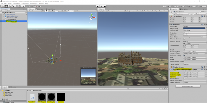
You will notice that in the inspector panel of the Main Camera GameObject there are three empty fields “Cubemap Left”, “Cubemap Right”, and “Equirect”. Will need to populate these fields with our textures in the “360 capture” folder. Drag the corresponding texture to the right place holder in the inspector panel of Main Camera as shown in the figure below:
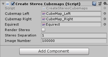
Next, double click on the “CreateStereoCubemaps” script to open it in visual studio. In the start function of this script (as shown in the figure below), you can see that we have instructed Unity to capture 25 frames per second.
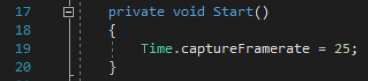
You do not need to study the rest of the script (unless you are interested in doing so), but to give you a general idea, we are capturing 25 monoscopic frames per second of the entire scene and saving each frame as a PNG file somewhere on our drive. Since the address of where the images are to be saved is hard-coded, you need to modify it to point to a location where you want the monoscopic images to be saved. On line 67, we have indicated this address (the orange text between the “ ”) along with a line of comment that tells you how to modify it (make sure you save the file after you have modified the address).

One easy way to update this address is to create a folder somewhere on your hard drive (you will need at least 1.5 GB of free space). Inside the folder click on the address bar on top and copy the address.
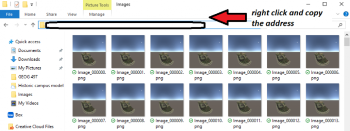
Make sure that the “\” in the address you have copied are replaced with “\\” when you replace it with the orange text in between “”.
Now if you play the scene, depending on the specifications of your computer system, the scene will perform differently. Since we are forcing Unity to capture 25 frames per second, the camera flight animation we’ve just created might not run very smoothly on older computers. If you play your scene now and notice lots of lagging, do NOT be alarmed. Let the camera flight animation finish (it could take a while on slower computers so be patient!), and then stop the scene from playing.
Now if you navigate to the folder, where you have instructed the script to save the PNG files, you will see that it is populated with around 1400-1500 images.
Creating the Video
Creating the Video
We now want to produce an MP4 movie from the individual 360° images. We will use the free command-line tool ffmpeg for this.
You can download a Windows build of the ffmpeg [104].
Extract the downloaded .zip and you get a folder with a bunch of files in it (similar to the image below). Make sure there are not two folders with the same name inside each other. The main executable ffmpeg.exe is located in the bin subfolder. We will directly run this .exe file, no installation is needed.
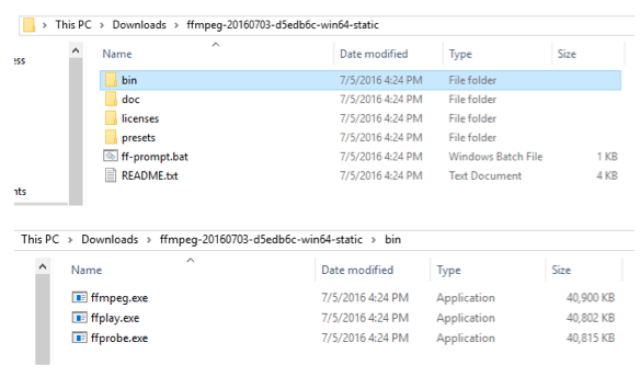
To be able to use the ffmpeg.exe as a command-line tool, let’s open a command prompt. Click on Windows and search cmd. Open cmd. You need to navigate to the location where you have extracted the content of the zip file. This is a very simple process.
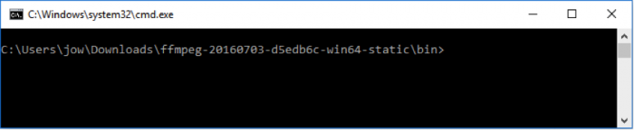
For example, I have extracted the contents of the zip file (i.e., the folder named ffmpeg-20210331-6ef5d8ca86-win64-static) to my desktop. What I need to do is to first open the command prompt. This can be done by clicking on the start button on the windows bar and type "command prompt". By default, the command prompt is at the root location for the current user of the OS (e.g., C:\Users\Pejman>). Now I need to access to the folder we have extracted to the desktop. To do so, you need to type:
cd desktop
and then press enter.
This simple command with navigating the command prompt to the desktop folder of your computer. Using a similar approach, we need to access the "ffmpeg-20210331-6ef5d8ca86-win64-static" folder. Now instead of typing the complete name of this folder which is rather long, you can simply type cd followed by a few letters of the folder name (i.e., ffmpe..) and then press the tab key on your keyboard. This will autocomplete the name based on what can be found on the desktop. The next step is to go to the bin folder using the same method. At the end of this process, you should be at this location within the command prompt:

For more help, please visit Digital Citizen [157].
The command that you need to type in now to have ffmpeg create a movie is given below, but you will have to make some small changes to adapt it to your system: The highlighted part needs to be replaced with the path to your folder where the images are saved. (In case you start by copy & pasting the command from this web page into the command prompt rather than typing it yourself, please check that the double quotes appear as straight double quotes, not curly ones and you also may have to retype hyphens and underscores as well. The safest approach is to type the complete command yourself, or paste it into a notepad and copy it from the notepad.). The last part of the address, namely “Image_%06d.png” is a pointer to the first image in this folder, and the program will then iterate through all the images based on this starting point. You do NOT need to change this last part.
ffmpeg.exe -r 25 -start_number 100000 -i "C:\Users\jow\Documents\UnityProjects\MyFirstUnityProject\LSCaptureFiles\Image_%06d.png" -vcodec libx264 -crf 15 -pix_fmt yuv420p myfirstunityproject.mp4
In the command, we tell ffmpeg that the produced video should use 25 frames per second, where the images are located and the pattern for how they are named, which video codec to use, etc. The final parameter is the name of the output file (myfirstunityproject.mp4) that will be generated. When you execute the modified command (by pressing enter), ffmpeg should start to process the images and create the MP4 video. Remember there are about 1400 frames.
When ffmpeg is done, there should now be a file called myfirstunityproject.mp4 in the bin subfolder of ffmpeg. You can move this file, for instance into your Documents folder.
Now run the video and have a look. If your standard video player is not able to display the video, we recommend that you go to VideoLan [158] to download and install VLC, a great and free video player, and then watch the video with this program.
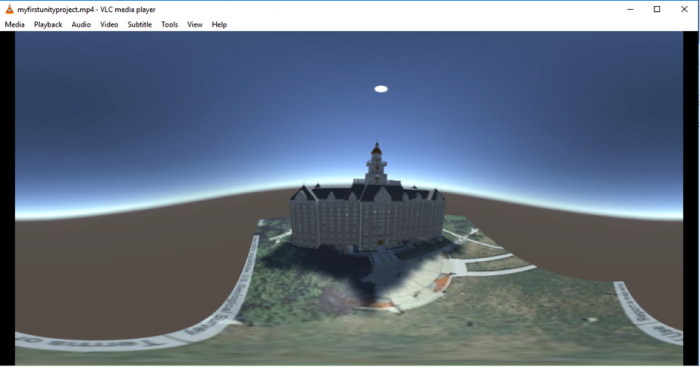
Changing the Movie Metadata
Changing the Movie Metadata
Now that we have the video our goal is to get it uploaded to a private YouTube channel and watch it with the cardboard on our smartphone. However, we first have to use yet another tool to adapt some of the metadata in the movie file so that YouTube will correctly recognize it as a 360° movie. We will follow Google’s Upload 360-degree videos [159] instructions.
- Download the 360 Video Metadata app [160] by clicking on the "360.Video.Metadata.Tool.win.zip".
- The downloaded .zip file contains a single .exe program called "Spatial Media Metadata Injector.exe". Start this program.
- In the dialog window that opens up, click the “Open” button and then navigate to our video file. After this, the name of the file should either appear in blue at the top of the dialog window.
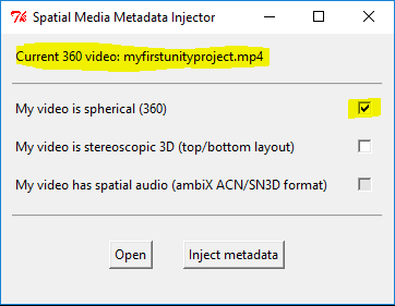 Credit: Google
 - Finally, select the "My video is spherical (360)" option at the top and then use the "Inject metadata" button to save the modified file under a new name. Let’s use “myfirstunityproject360.mp4” as the name. The resulting file is the one that we want to now upload to YouTube.
Uploading the Video to YouTube
Uploading the Video to YouTube
The final steps of this walkthrough will require that you have a YouTube account and channel. That doesn’t mean that the 360° videos produced in this course will be publicly available for everyone. It is possible to use your channel only to share these with particular people, like everyone in this class. If you do not have a YouTube account/channel yet, please follow the Create an account on YouTube [161] instructions to create these.
You should now be on the main page for your YouTube channel. Click on the “Upload” link at the top to upload a new video. Set the field to determine who can watch the movie to “Private” for now. When you later want to share a video with the class, you can instead set this to “Unlisted” and share the link to the video. Unlisted means that everyone with the link can watch the video but it won’t be visible to anyone else as part of search results on YouTube. Now, drag the video file myfirstunityproject360.mp4 from the Window Explorer on to the upload icon. The upload will start immediately. After the upload is completed, YouTube will start processing the file. After this has finished as well, you can click “Done”.
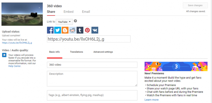
The video should now be listed in the YouTube Studio [162] under the videos tab.
Clicking on it should take you to a page as shown below, where you can play your video, or open its link in a different tab.
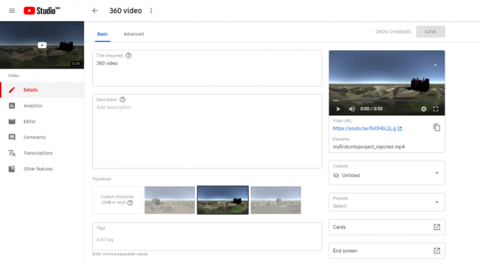
You should now be able to watch this video on YouTube like any other video. You should, in addition, be able to look around during the camera flight either by dragging with the left mouse button pressed or by using the arrows in the top left corner of the video. By clicking the Settings icon at the bottom, you may be able to increase the resolution at which the video is displayed unless it is already displayed at the highest available resolution.
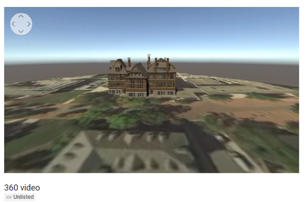
If you play this video on your phone, you will get the option to see it in VR mode when you switch to full screen. If you select that option, you can put your phone in a CardBoard and enjoy your first VR creation.
You can check out other VR videos on YouTube at YouTube Virtual Reality [163].
Note: Make sure your YouTube app is up to date!
Tasks and Deliverables
Tasks and Deliverables
Part 1: Participate in a Discussion
Please reflect on your 3D spatial analysis experience, using ArcGIS Pro; anything you learned or any problems that you faced while doing your assignment as well as anything that you explored on your own and added to your 3D spatial analysis experience.
Part 2: Assignments
The homework assignment for this lesson is to apply the techniques you learned in this lecture to the historic campus scene that you already saw in the previous lesson (it should be already in your “MyFirstUnityProject” project under the “Historic Campus” folder). You are supposed to create a nice camera animation and produce a stand-alone windows application as well as a 360° movie. The video should be uploaded to your YouTube channel and shared together with your Windows application with the rest of the class by posting the links and a short description on the forums. Finally, you are supposed to provide constructive feedback on a video created by one of your classmates and submit a write-up reflecting on this assignment.
The assignment has several tasks and deliverables with different submissions deadlines, all in week 10, as detailed below. Successful delivery of the tasks 1-6 is sufficient to earn 90% on this assignment. The remaining 10% is reserved for efforts that go "above & beyond" by improving the historic campus model, e.g. in ways suggested below, before creating the video and stand-alone Windows application.
Task 1: Create camera animation
For this assignment, you will use the historic campus scene from Lesson 8. We suggest you start with a fresh download of the Unity project: Historic Campus [164]. The campus models have already been imported and placed in a scene (main) and things should look like in the screenshot below when opening the project in Unity. You are now supposed to create a ~1.5min camera flight over the scene using what you learned about animating the camera in this lesson. But before you start with the camera flight, you may want to think about what you want to do for "above & beyond" efforts (see details below) as this may have an effect on the camera trajectory you want to create (e.g. in case you are going to add additional models to the scene).
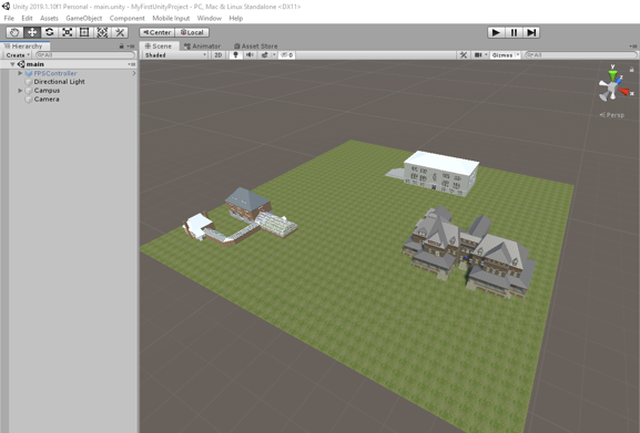
Task 2: Produce a stand-alone Windows application
Produce a stand-alone Windows application showing your camera animation as you learned in this lesson. Please note that if you put in work for above & beyond points, this needs to be done before creating the Windows application so that these efforts are included.
Deliverable 1: Create a .zip file containing all the files and folders of your built.
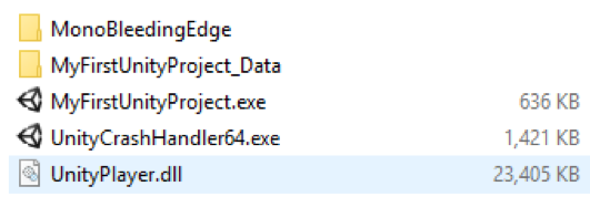
Upload the application to the PSU Box Comunity Folder [165] and include the link to your application when posting on the Lesson 8 Video Discussion (see Task 4).
Task 3: Produce 360° video
Produce a 360° video showing your camera animation as you learned in this lesson. Don't forget to adapt the meta information before uploading the video to your personal YouTube channel. Please note that if you put in work for above & beyond points that should be visible in the video, this needs to be done before creating the video so that these efforts are included.
Deliverable 2: Upload the 360° video to your YouTube channel and share it via a link. Include the link when posting on the Lesson 8 Video Discussion (see Task 4).
Task 4: Share stand-alone application & video
Deliverable 3: Create a post on the Lesson 8 Video Discussion including the links for your Windows stand-alone application & 360° video. Add a one-paragraph description of what you did to improve the model for above & beyond points, if anything. If your above & beyond efforts are only visible/audible in either the 360° video or the stand-alone application, please make this clear as well.
Task 5: Constructive feedback on other student's video
Watch a video posted by one of your classmates and write down 1-2 paragraphs in which you provide constructive feedback. If possible, please pick a video that has not yet received any feedback. Comment on the technical and aesthetic quality of the video and, if applicable, the extensions made to the model. Make suggestions on how the work can be improved or extended. If the description mentions that some additional effort is only included in the Windows stand-alone application, you can feel free to ignore that part.
Deliverable 4: Post your feedback as a reply to the respective video post on Lesson 8 Video Discussion.
Task 6: Reflection Paper
Create a ~700 words write-up reflecting on what you learned in this assignment, what problems you ran into, if and how you were able to resolve these, etc. Please also include a complete description of things you did for above & beyond efforts. Provide some final assessment of your experience with Unity.
Deliverable 5: Submit your write-up to the Lesson 8 Assignment.
Above & beyond:
This part of the assignment is for allowing you to let your creativity run free to extend or improve the historical campus scene and/or explore some features of Unity development on your own based on one of the many tutorials available on the web. What you do is up to you; the following are just two suggestions for directions in which you can think:
- Add additional models to the historical campus scene: You can extend the scene by adding additional objects. This could be your own building model from Lesson 3, some free assets you find by browsing the Unity Asset Store [121] (view How to use the Asset Store [166] for instructions), or some other free 3D models available on the web. The purpose of this assignment is to demonstrate your Unity skills to us, so realism is not important here. But what you add should generally fit the historic campus scene (additional buildings, other tree or plant models, models of people, etc. but no spaceships, robots, or the likes). If you want to include your own building model but the building is already there, feel free to import it and place your model at a different location in the scene. Please don't go overboard with the number of objects you add; a very few to show that you are able to import models and place them in the scene is all that it takes.
- Add some background music, other sound effects, or commentary: Adding sounds and background music to a scene in Unity is not complicated but you should only try to include this into the Windows stand-alone application with the standard camera object because recording sound won't work with the 360° video recording. The first four minutes of this Beginner Unity Tutorial [167] will give you a basic understanding of what needs to happen: The audio file (.mp3, .wav, etc.) you want to use needs to put into the Assets folder of your project. The main camera object needs to have an AudioListener component and this component needs to activated (checkbox at the top left). Then you can attach an AudioSource component either to the camera itself or any other GameObject in the scene. Attaching it to the camera itself works fine for background music or commentary while attaching it to objects in the scene works best for 3D sound that should get louder when the camera approaches a particular object or location in the scene. Finally, the audio track needs to be dragged from the Assets window onto the AudioClip property of the AudioSource component.
If you are looking for some relaxing background music, you can browse freesound [168]for a suitable track that is freely available. Alternatively, or in addition to using music, you can record your own commentary describing either the scene or what you did for this assignment and have this played during the camera flight. If you experience any problems with adding sound, feel free to help each other out in Lesson 8 Discussion.
Helpful advice:
We highly recommend that, while working on the different tasks for this assignment, you frequently create backup copies of your Unity project folder so that you can go back to a previous version of your project if something should go wrong.
For the camera animation, we recommend using many intermediate keyframes unless the camera is just moving in a straight line. In particular, try to not have a rotation of more than 90° between two successive keyframes in the animation.
| Criteria | Full Credit | Half Credit | No Credit | Possible Points |
|---|---|---|---|---|
| Camera flight has the correct length, is smooth and aesthetically pleasing. | 3 pts | 1.5 pts | 0 pts | 3 pts |
| Windows stand-alone application is shared via Box and shows the camera flight. | 3 pts | 1.5 pts | 0 pts | 3 pts |
| Video is shared via YouTube and shows the camera flight. | 3 pts | 1.5 pts | 0 pts | 3 pts |
| Video has been correctly created and uploaded as a 360° video allowing to look around while the camera is moving over the scene. |
3 pts | 1.5 pts | 0 pts | 3 pts |
| Above & Beyond: The number of points varies depending on how much effort was required (e.g. placing an additional 3rd-party 3D model in the scene will give fewer points than placing a self-made model or adding background music to the scene). | 3 pts | 1.5 pts | 0 pts | 3 pts |
| Total Points: 15 |
| Criteria | Full Credit | Half Credit | No Credit | Possible Points |
|---|---|---|---|---|
| Paper clearly communicates what you learned in this assignment, what problems you ran into, if and how you were able to resolve these, etc. Paper also includes a complete description of things you did for above & beyond efforts and a final assessment of your experience with Unity. | 5 pts | 2.5 pts | 0 pts | 5 pts |
| Write-up is of the correct length and is well and thoughtfully written. | 5 pts | 2.5 pts | 0 pts | 5 pts |
| The document is grammatically correct, typo-free, and cited where necessary. | 2 pts | 1.0 pts | 0 pts | 2 pts |
| Total Points: 12 |
Summary and Tasks Reminder
Summary and Tasks Reminder
In this lesson, you significantly extended your Unity skills by learning how to add a user-controlled avatar and enable colliders for the objects in the scene, and how to create a camera animation with the Animation View. We also spoke about the different ways to create VR experiences for different devices with Unity, including using 360° videos for the Google Cardboard as an efficient option for devices that may not have the hardware performance to run VR applications in real-time. We have now come full circle with regard to the 3D and VR application building workflows we discussed in Lesson 2. We hope that these last two lessons focusing on Unity and the skills you acquired in them will prove to be a helpful complement to your 3D modeling and analysis repertoire.
Reminder - Complete all of the Lesson 8 tasks!
You have reached the end of Lesson 8! Double-check the to-do list on the Lesson 8 Overview page to make sure you have completed all of the activities listed there before you begin Lesson 9.
Lesson 9: Unity III
Overview
Overview
This will be both a practical and theoretical lesson that shows you a complete Unity project with some advanced functionalities. You will be provided with a simple “City builder” unity game where you can instantiate buildings in a city and animate cars to patrol over a specified path. The objective is not to teach you how to program this game, as it will be outside of the scope of this course, but rather demonstrate to you what is possible to be done in Unity with a few classes and some built-in features of the game engine. Furthermore, we will explore some of the VR specific mechanics that are used in game engines such as Unity for making the experiences more interactive (e.g. different types of locomotion, and interaction with objects).
Learning Outcomes
By the end of this lesson, you should be able to:
- Have an impression of how much effort is needed to create a simple game such as City Builder
- Have a general understanding of some of the advanced features of Unity such as AI (artificial intelligence) and dynamic GameObject instantiation
- explain different locomotion mechanics used in VR to move the player around a scene
- explain different interaction mechanics used in VR to interact with objects
Lesson Roadmap
| To Read |
|
|---|---|
| To Do |
|
Questions?
If you have any questions, please post them to our "General and Technical Questions" discussion (not e-mail). I will check that discussion forum daily to respond. While you are there, feel free to post your own responses if you, too, are able to help out a classmate.
The City Builder Game
The City Builder Game
Introduction
Download the City Builder Unity Package [104]. The package includes all the resources used in the city builder game. This is a very simple game, where the user can select different buildings from a menu and place them in specific locations in a city (only some areas allow for placing a building) using their mouse. When selecting a building to be placed in the city, its base will change color. The red color indicates that the current location of the building is illegal (and therefore it cannot be placed there), whereas the blue color indicates a legal location. The color of the base will continuously change as the user moves the building in the city to find a location to place it. Once the building is in a legal location, the user can click down on the mouse (left click) to place the building in the city. If the user clicks on an already placed building, the base of the building will become purple, indicating that it has been selected. Once selected, buildings can be removed from the city by pressing the “D” button. Moreover, the user can move the camera along the X and Z axes using the arrow keys on the keyboard (left, right, up, and down keys). This will help the user navigate the environment when placing buildings. Lastly, there is a car that patrols a street over a specified path. A quick video of this game can be seen below:
Video: City Builder Demo (00:54) This video is not narrated.
Import this package into a new Unity project. Once the import is done, navigate to the folder “City Builder”, and open the scene with the same name “City builder”. Make sure your “maximize on play” option in your game window is enabled, and then play the scene.
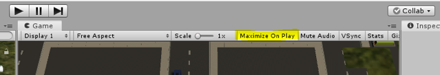
When the scene is playing, you can see a blue car patrolling over a specified path. You can use the arrow keys on your keyboard (left, right, up, down keys) to move the camera along the X and Z axes. If you click on the buttons of the menu on the left side of the screen, you can select different buildings to place in the city. Select a building, move it over a legal position and left click with your mouse to place it down. Place a few more buildings in the city. Click on a building that is already in the city. You will notice that its based will change color to purple. Press the “D” button on your keyboard to delete this building.
Setting up the City Builder from Scratch
Setting up the City Builder from Scratch
To give you an idea of how such a scene can be set up, we will go through a series of steps to recreate the City Builder scene. All the resources you need are already inside the “City Builder” folder.
- Create a new scene in the City Builder folder, and name it “My City Builder”
- Navigate to the “Prefabs” sub-folder and drag the “Plane” prefab into the scene. Reset its position to (64,-0.2,0) and change its scale to (50,1,50). Notice that the plane object already has a Box Collider attached to it.
- Select the Main Camera GameObject and set its position to (65,85,-85) and orientation to (74,0,0)
- Drag the “Roads” prefab onto the scene and set its position to (42,1.1,-17). This is a rather detailed object, with many child objects under it. If you expand this GameObject and examine its children, you will notice that some of them have the tag “Street”, and some of them do not. We use these tags later when we want to decide whether the building, we want to add to the city is being placed on the street or not. More precisely, if the building object that is following our mouse pointer collides with another object with either the tag “Street” or “Building” it is considered an illegal location.
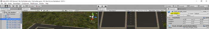 Credit: ChoroPhronesis [41]
 - Drag the “Car” Prefab onto the scene and set its position to (59.5,0,-1.2). If you look at the inspector panel of the car GameObject you have just added to your scene, you will notice that it has a script attached to it called “Car AI”. This script utilizes the AI engine of Unity which implements a path finding algorithm, so the car moves through several “Patrol points”. These points are not assigned yet, but we will do them shortly. Apart from this script, the Car object also has a component called “Nav Mesh Agent”. This is a native unity component as part of its AI engine that marks a GameObject as a navigatable agent. Since we want the car to act as such an agent, we need to have this component added it. There are many parameters that you can set for the Nav Mesh Agent including the movement and turn speed, acceleration, obstacle avoidance, etc. for more information watch NavMesh Agent - Unity Official Tutorials [169].
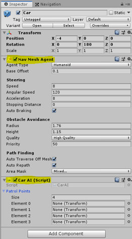 Credit: ChoroPhronesis [41]
 - Before adding the patrol Points to the Car AI script, we must tell unity which parts of our scene are “walkable” by the Nav Mesh Agent. To do this, go to the “Window” menu on top of the Unity editor, Select AI -> Navigation.
-
A new panel called Navigation will be opened on the right side of the editor. Select the “Bake” tab on this panel and click on the Bake button.
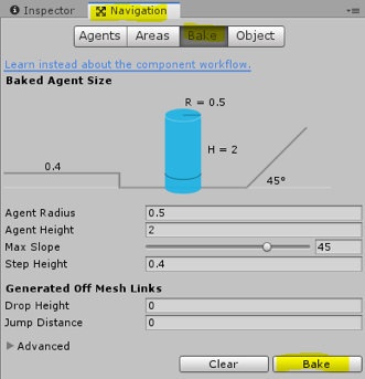 Credit: ChoroPhronesis [41]
After a few seconds your scene should look like this:
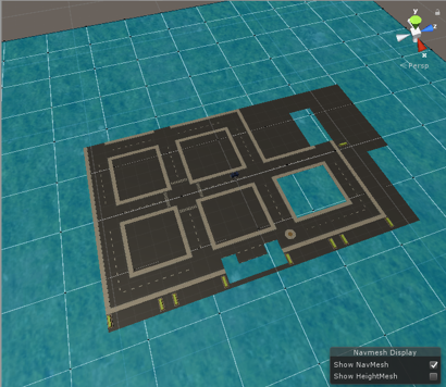 Credit: ChoroPhronesis [41]
 -
Navigate to the Prefabs folder again and drag the “Waypoints” prefab onto the scene, and set its position to (62.5,0,-70.2). This GameObject has four children, where each act as a patrol point for our Car AI script. You can inspect the position of each these points in the scene. Now, if we select our Car GameObject again, and look at its properties in the inspector menu, we can add patrol points to the Car AI script. Simply drag each waypoint (children of the WayPoint object named Waypoint 1 to 4) to each element (0 to 3) place in the Car AI script.
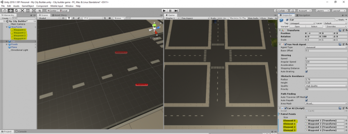 Credit: ChoroPhronesis [41]
 - Hit play, and you should have your car move from one Patrol Point to the next over a loop. As an exercise (not evaluated), change the placement of the Waypoints in the scene so the car goes around a block.
-
Inside the City Builder folder, navigate to the “Scripts” subfolder. Drag the “BuildingManager”, “BuildingPlacement”, and “MoveCamera” scripts onto the Main Camera GameObject in your scene.
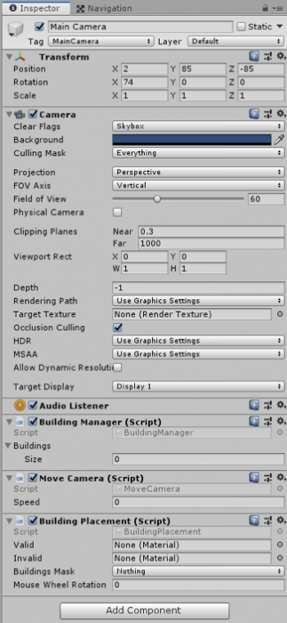 Credit: ChoroPhronesis [41]
 -
Most of our functionalities are covered by these three scripts, so we will briefly go over them. The “Building Manager” script takes care of generating the menu on the left side of the screen and adding buttons to it to the number of buildings we want to have in our menu. You can see that this script has a property called “Buildings” in the editor. If you expand this option, you will see a placeholder for “Size”. Change this value to 3. This means that we want our menu to hold three buttons each representing a different building, so we can select them and place them in the city. When you change the value to 3, you will notice that three new empty placeholders are shown. Go to the Prefabs subfolder again, and drag the Blue, Brown, and Green building prefabs to each of those placeholders.
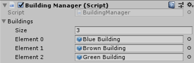 Credit: ChoroPhronesis [41]
Now to the number of buildings we have added to this list, we will have buttons with the same name as the building prefabs generated for us. Clicking on each button will inform the “Building Placement” Script, which building to generate and attach to the mouse pointer. For more detail, please examine the fully commented script of “Building Manager”.
-
Next, we will examine the “Building Placement” script. There are three properties for this script in the editor that we need to change. First, we need to add different materials for the “base” of the buildings to indicate illegal and legal positions of the building by means of color. Navigate to the “Materials” subfolder and drag the “Valid” material to its corresponding placeholder in the inspector panel. Do the same for the “Invalid”. Once the “Building Manager” script informs the “Building Placement” script which building is requested to be generated, the “Building Placement” script will instantiate (create a copy on the fly) that building and will attach it to the position of the mouse pointer. Furthermore, it will use the valid and invalid materials we’ve just added to the component, so it can change the color of the base of the buildings to red when they collide with buildings and streets (i.e. invalid), or otherwise blue (i.e. valid).
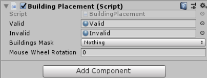 Credit: ChoroPhronesis [41]
The “Building Placement” script is also monitoring the clicking of the mouse by the user. If there is a building attached to the mouse pointer and the position is legal and the user clicks on the mouse, it will place the building on that exact location and will disable its base (so it looks realistic when placed in the city). Notwithstanding, we also want the user to be able to click on a building that is already placed in the city so they can remove it. This means that our “Building Placement” implements a second check condition to see if no building is attached to the mouse pointer at the moment when the user clicks on the left mouse button. If that is the case, it also checks whether what the user has clicked on is actually a building or not. For this check, our script uses the “Building Mask” property, as shown in the editor. All the building prefabs we have added to the “Building Manager” script already belong to the “Building” layer. All we need to do is tell unity which layer to look for when the user clicks on objects in the city. As such, we need to create a new layer and set that as our Buildings Mask. For this, click on the “Layer” dropdown menu on top of this panel, and select “Add Layer”.
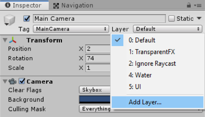 Credit: ChoroPhronesis [41]
Create a new layer called “Building” and set the Building Mask to that layer (this layer should already exist in your layer list, if not, create it).
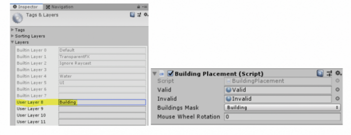 Credit: ChoroPhronesis [41]
 -
The last property we need to set in the unity editor is related to the “Move Camera” script. We need to indicate a speed value for the movement of the camera, so we can move it using the arrow keys. Set this value to 15.
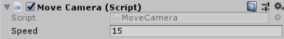 Credit: ChoroPhronesis [41]
 -
That is all you needed to do in order to set up a fully working City Builder scene with the assets that were provided to you. Press play and enjoy your creation. You should be able to move the camera around, place buildings in designated areas of the city and remove them. You may notice that we have not covered which script handles the color changing of the base of buildings when they are selected, as well as the function for deleting them. This is because, each of the building prefabs we added to the “Building Management” script has a script called “PlacableBuilding” that takes care of these functions, and we do not need to set anything up for them to work. However, in short, once a building that is already placed in the city is clicked on, the “Building Placement” script detects which exact building was clicked and triggers the “PlacableBuilding” script attached to it. This script will then change the base color of that building to purple, and if the user presses the “D” key, it will remove that building from the scene.
You can also watch this complete video tutorial on how to assemble this scene.
Video: CityBuilder Instructions (6:39) This video is not narrated.
Note: Although we did not directly go over the scripts line by line, I strongly recommend that you look at the scripts inside the “Scripts” subfolder to have a better understanding of how some of these functions are implemented in C#. All the scripts are fully commented for your convenience.
Common Mechanics Used in VR Development
Common Mechanics Used in VR Development
Most of the mechanics used in desktop experiences can also be used in VR. However, not all of them are best choices for VR experiences. Two of the most prominent examples are locomotion and interaction mechanics. In this section, we will briefly explore the different locomotion and interaction mechanics that are designed specifically for VR experience.
Locomotion in VR
Locomotion can be defined as the ability to move from one place to another. There are many ways in which locomotion can be implemented in games and other virtual experiences. Depending on the employed camera perspective and movement mechanics, the users can move their viewpoint within the virtual space in different ways. Obviously, there are fundamental differences in locomotion possibilities when comparing 2D, 2.5D, and 3D experiences. Even within the category of 3D experiences, locomotion can take many different forms. To give you a very general comparison, consider the following:
Locomotion in 2D games is limited to the confines of the 2D space (X and Y axes). The camera used in 2D games employs an orthogonal projection. Therefore, the game space is seen as “flat”. In these experiences, users can move a character using mechanics such as “point and click” (as is the case in the most 2D real-time strategy games) or using keystrokes on a keyboard or other types of controllers. The movements of the orthogonal camera in these experiences is also limited to the confines of the 2D space. Consequently, the users will not experience the illusion of perceiving the game through the eyes of the character (e.g. Cuphead [170], Super Mario Bros, [171] etc.). Evidently, the same type of locomotion can be employed in the 3D space as well. For instance, in the City Builder game, we have seen in this lesson, the camera uses a perspective projection. However, the locomotion of the user is limited to the two axes of X and Z. The three-dimensional perspective of the camera (viewpoint of the user), however, creates an illusion of depth and a feeling of existing “in the sky”. In more sophisticated 3D games, such as First-person shooters (FPS [172]) where it is desired that the players experience the game through the eyes of their character, the feeling of movement is entirely different. We stress the word “feeling” since the logic behind translating (moving) an object within a 2D space compared to a 3D space from one point to another is not that different. However, the differences in the resulting feeling of camera movements are vast (unattached distant orthogonal vs. perspective projection through the eyes of the character). In many modern games (not necessarily shooters) with a first-person camera perspective, the players can be given six degrees of freedom for movement and rotation.
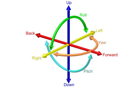
Video: Making an FPS Game with Unity using the Asset Store (3:32)
In this video, we've created a first-person shooter game in unity by using content from the unity asset store. Our goal in this video is to show the assets from the unity asset store that we've used to build this game from the ground up. The assets used in this project are all available on the unity asset store with links in the description below. Let's take a look at our first-person shooter game and see what assets are used to create it. This is a first-person game where you are armed with a single pistol and must fight the evil robots around the environment. The enemy robots are fully textured and animated and react to being damaged by the player. The environment is filled with dynamic physics props and reacts to being pushed around or shot by the player. The first-person controller functionality is provided by the ultimate first-person shooter package. We move around with the WASD keys and click the left mouse button to shoot. The UFPS package provides our game with the player movement controls and a shootable and reloadable pistol. The environment in our game is provided by the snaps prototype pack. The snaps prototype asset pack is a set of themed 3d models built using pro builder. We have set up various levels using the walls, ceilings, and floors included in the snaps asset. We then use Unity's built-in enlightened light mapper to add both precomputed and baked global illumination for additional shadowing. The props in our game are also provided by the snaps prototype pack. We've attached both the rigidbody and a mesh Collider, set to convex, to each dynamic prop, which allows the player and the enemy robots to crash through the environment in a dynamic way. Lastly, our environment is topped off with a skybox from the all-sky asset. The skybox is a nice background in our level for the player to see off in the distance and outside the windows. In addition, unity standard lighting system and built-in light mapper use the scene skybox for additional detail and more even lighting on our meshes. We've used the robot warriors asset for a robot enemies. The robot warriors asset comes with three fully textured, rigged, and animated robots. We've set up two robot enemies using the models and animations from robot warriors. To integrate our enemy robots into our game, we've hooked it up to the damage system in the UFPS so that the robot enemies take damage when we fire our pistol at them and die once they take enough damage. We've use Unity's standard built-in nav mesh agent component to allow our robot enemies to walk around the map without hitting the walls of the level. We have also used the volumetric lighting solution Aura2, to provide atmosphere. Volumetric lighting can help us simulate an environment in which light shafts can be seen. By using Aura2's volumetric lighting system, we were able to attach a red spotlight to each robots eye, giving them a menacing red cone of light wherever they look. Finally, we've used Unity's post-processing stack to provide color grading, tone mapping, bloom, and anti-aliasing over the final image. This brings our final render together visually. As you can see, by using assets from the Unity asset store, we can quickly create an environment, integrate believable characters, and also implement gameplay functionality. All of the assets shown are available now on the unity asset store. To learn more click the link in the description below. Thanks for watching.
The FPS Controller we used in the previous lessons is an example of providing such freedom (except for rotation along the Z-axis). The mechanics for the movement in such games, however, are almost all the time through a smooth transition from one point to another. For instance, in the two different locomotion mechanics we used in this course (FPS Controller, and camera movement) you have seen that we gradually increase or decrease the Position and Rotation properties of the Transform component attached to GameObjects. This gradual change of values over time (for as long as we hold down a button for instance) creates the illusion of smoothly moving from one point to another.
As was previously mentioned, there are many ways in which locomotion can be realized in virtual environments, depending on the type and genre of the experience, and the projection of the used camera. Explaining all the different varieties would be outside the scope of this course. Therefore, we will focus on the one that is most applicable in VR.
The experience of Virtual Reality closely resembles a first-person perspective. This is the most effective way of using VR to create an immersive feeling of perceiving a virtual world from a viewpoint natural to us. It does not come as a surprise that in the early days of mainstream VR development, many employed the same locomotion techniques used in conventional first-person desktop experiences in VR. Although we can most definitely use locomotion mechanics such as “smooth transition” in VR, the resulting user-experiences will not be the same. As a matter of fact, doing so will cause a well-known negative effect associated with feelings such as disorientation, eyestrain, dizziness, and even nausea, generally referred to as simulator sickness.
According to Wienrich et al. “Motion sickness usually occurs when a person feels movement but does not necessarily see it. In contrast, simulator sickness can occur without any actual movement of the subject” [1]. One way to interpret this is that simulator sickness is a form of physical-psychological paradox that people experience when they see themselves move in a virtual environment (in this case through VR HMDs) but do not physically feel it. The most widely accepted theory as to why this happens is the “sensory conflict theory” [2]. There are, however, several other theories that try to model or predict simulator sickness (e.g. the poison theory [3], the model of negative reinforcement [4], [5], the eye movement theory [4-5], and the and the postural instability theory [6]). Simulator sickness in VR is more severe in cases where the users must locomote, particularly using smooth transition, over a long distance. As such, different approaches have been researched to reduce this negative experience. One approach suggested by [1] is to include a virtual nose in the experience so the users would have a “rest frame” (a static point that does not move) when they put on the HMD.
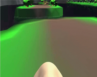
Other approaches such as dynamic field of view (FOV) reduction when moving or rotating have also shown to be an effective way to reduce simulator sickness.
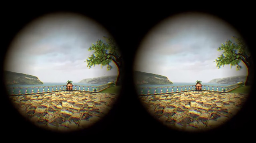
In addition to these approaches, novel and tailored mechanics for implementing locomotion, specifically in VR, have also been proposed. Here we will list some of the most popular ones:
- Physical movement: In the earlier version of VR HMDs, no external sensors were used for tracking the position of the users. As such, physically moving around a room and experiencing translation (movement) inside the virtual environment was not easily achievable (in few examples other forms of sensors such as Microsoft Kinect were used for this purpose to some extent). In the newer models of HMDs however, external sensors were added to resolve this shortcoming by providing room-scaled tracking. For instance, Oculus Rift, and HTC Vive both have sensors that can track the position of the user within a specific boundary in a physical space. This allows the users to freely and naturally walk around (as well as rotate, sit, and jump) within that boundary and experience the movement of their perspective in VR. As we have already seen in Lesson 1, the latest generations of HMDs such as Oculus Quest employ the inside out tracking technology which eliminates the need for external sensors. Using these HMDs, the users are not bound to a specified physical confine, and they can freely move around in a much larger physical space. This method of locomotion is the most natural one we can use in VR.
Video: Oculus Insight VR Positional Tracking System (Sep 2018) (02:39)
Over the last three years, the Occulus team has built revolutionary inside-out tracking technology. That's what we call Oculus insight. Insight uses four ultra wide-angle sensors and advanced computer vision algorithms to track your exact position in real-time without any external sensors. It's thanks to this technology that you can move around freely, fluidly, and fast. It's really cool. Now let's take a look at how insight works. First of all, it uses the four wide-angle sensors on the headset to look for edges, corners, and pretty much any distinct feature in the environment. It then builds a three-dimensional map that looks like a sparse point cloud. These are the green and blue dots that you see here. The system combines this map with gyroscope and accelerometer input and generates a very precise estimate of your head position every millisecond. Insight is a very flexible and robust system. It relies on all the different features in the environment for tracking. So floors and ceiling, walls, rugs, art on the wall, window fixtures, curtains, you name it, and even furniture. Now, this flexibility is important particularly in more challenging environments, like for example, a room with a super shiny floor or with bare white walls with no texture, with nothing on them. And we've tested Oculus Insight in hundreds of different home spaces and we're gonna continue to do that to fine-tune it over time. Now many of you have built room-scale experiences for Oculus Rift. Oculus Insight goes beyond room-scale and it works in much larger spaces without any external sensors. Oculus Insight also powers the Guardian system in Oculus Quest. Just like on Rift, Guardian is what helps keep you safer while you're in VR. And Oculus Insight supports multi-room guardian, so, I love this guy, so you can easily take your headset to different parts of your home, your friend's home, or your office, and it will remember the Guardian setup for each of those spaces.
- Teleportation: teleportation is still considered the most popular locomotion system in VR (although this may change soon due to the emergence of inside out tracking technology). It allows users to jump (teleport) from one location to another inside a virtual environment. There are different types of teleportation as well. The most basic form is instant teleportation where the perspective of the user is jumped from one location to another instantaneously when they point to a location and click on their controller.
Other forms of teleportation include adding effects when moving the user’s perspective from one location to another (e.g. fading, sounds, seeing a project of the avatar move, etc.), or providing a preview of the destination point before actually teleporting to that location:
Another interesting and yet different example of teleportation is the “thrown object teleported”, where instead of pointing at a specific location, the user throws an object (using natural gestures for grabbing and throwing objects in VR as we will discuss in the next section) and then teleport to the location where the object rests.
- Arm swing: this is a semi-natural way to locomote in VR. Users must swing their arms while holding the controllers, and the swinging gesture will translate their perspective in the virtual environment. The general implementation of this mechanic is in such a way that the faster users swing their arms, the fast their viewing perspective moves in the virtual environment. This is a rather useful locomotion mechanic when the users are required to travel a relatively long distance, and you do not want them to miss anything along the way by jumping from point to point.
- Grabbing and locomoting: Imagine a rock-climbing experience in VR, where the user must climb a surface. An arm swing gesture is probably not the best locomotion mechanic in this case to translate the perspective of the user along the Y-axis (as the user climbs up). By colliding with and grabbing GameObjects such as rocks however, the user can locomote on the X, Y, or Z axes in a more natural way. This locomotion mechanic is used in many different VR experiences for climbing ladders, using zip-lines, etc.
- Dragging: this is a particularly interesting and useful locomotion technique, specifically for situations where the user a top-down (overview) perspective of the virtual environment. Consider a virtual experience where the size of the user is disproportionate to the environment (i.e. they are a giant) and they need to navigate over a large terrain. One way to implement locomotion in such a scenario is to enable users to grab the “world” and drag their perspective along the X or Z axes.
There are many other locomotion mechanics for VR (e.g. mixing teleportation and smooth movement, run in-place locomotion, re-orientation of the world and teleportation together, etc.) that we did not cover in this section. However, the most popular and widely used ones were briefly mentioned.
References
[1] C. Wienrich, CK. Weidner, C. Schatto, D. Obremski, JH. Israel. A Virtual Nose as a Rest-Frame-The Impact on Simulator Sickness and Game Experience. 2018, pp. 1-8
[2] J. T. Reason, I. J. Brand, Motion sickness, London: Academic, 1975.
[3] M. Treisman, Motion Sickness: An Evolutionary Hypothesis” Science, vol. 197, pp. 493-495, 1977.
[4] B. Lewis-Evans, Simulation Sickness and VR-What is it and what can developers and players do to reduce it?
[5] J. J. La Viola, "A Discussion of Cybersickness in Virtual Environments", ACM SIGCHI Bulletin, vol. 32, no. 1, pp. 47-56, 2000.
[6] G. E. Riccio, T. A. Stoffregen, "An ecological theory of motion sickness and postural instability", Ecological Psychology, vol. 3, pp. 195-240, 1991.
Interaction in VR
Interaction in VR
Interactions with GameObjects in non-VR environments are limited to conventional modalities and their affordances. In desktop experiences, for instance, interactions are limited to pointing at objects and graphical user interface element. In certain gaming consoles, however, such as Nintendo Wii [184] and Xbox Kinect, users can perform natural gestures to interact with objects in a game or to perform actions.
Interaction with GameObjects in VR can be considerably more natural compared to desktop experiences. The immersive nature of VR HDMs combined with the possibility of locomotion in a natural point of view affords a much closer interaction experience to real-life compared to any other gaming console or desktop. Thanks to the power of sensors and controller data in VR headsets, we can constantly track the position, orientation, and intensity of hand movements in VR. As such, users can use natural gestures for interaction with different types of objects while perceiving them from a natural viewpoint.
Users can interact with objects by reaching out and grabbing them when they are in their proximity, or they can grab them from distance using a pointer. Once an object is grabbed, users can use the physics properties to place them somewhere in the virtual environment, throw them, and even change their scale and rotation.
Video: Natural Virtual Hand Interaction with Puzzle Cube in VR (1:13) This video is not narrated.
An example of grabbing an object from distance using pointers:
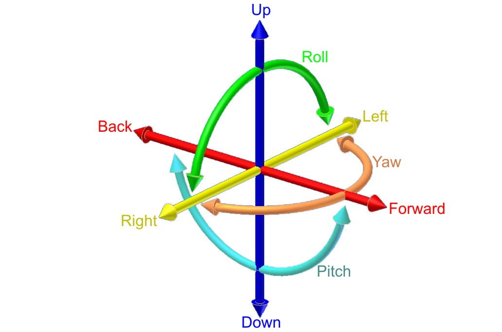
More natural forms of interaction in VR are via gestures. For instance, users can spin a wheel using a circular gesture or pull down a lever using a pull gesture. The popular VR archery game is a prime example of using natural gestures to interact with game objects.
Similar to the bow and arrow, some objects such as a fire extinguisher are used by two hands in real-life. The same principle could be applied in VR, where the user grabs the capsule with one hand and the hose with another. An overview of some of these interaction mechanics is demonstrated in the videos below from one of the most popular VR plugins for Unity called VRTK.
Video: [Basics] Grab attach mechanics (5:57)
[Music]
Hello and welcome to another VRTK tutorial. In today's tutorial, we're going to be covering the different grab attach mechanics. So to do that, I'm just going to jump into scene 21, which is 0:21 control out grabbing object with joints. And this scene already shows us the different grab attach mechanics that are on offer. And the grab attach mechanics can be seen in script, interactions, grab attach mechanics. And these are the different types. And if we click on one of these, you'll see, for instance, on here we've got the spring joint grab attach. We'll see that in action in a moment. On the red cube, we've got the fixed joint grab attach. And on the green cube, we've got the track object grab attach. If we move over to this wheel, if we look at the wheel on here, we've got the rotator track grab attach. And if we look at the gun down here, this one has got the child of controller grab attach. So the main difference between the grab attaches is they all slightly attach the object to the controller in different ways or by doing different things. So the fixed joint and the spring joint both use a joint to fix it to the controller. And this can be very useful, for instance, if you pick up a fixed joint object it holds very close to the controller, but if you bang it against something, the joint will break and it will automatically drop out your hand, which can be quite useful if you're going for that level of realism that if you bang your hand against the wall, you may drop the gun or something like that. Obviously a spring joint can give you the feeling that something is not quite being tracked directly with you, so it's always kind of springing away. And you can change all the springs settings within Unity to set that up however you want. And then the track object, it actually uses the velocities of the controller. So to move that object to follow the controller around and this can be very useful as well that it can then also interact with other rigid bodies in the scene, rather than just disconnect like the fixed joints or the spring joint does. We've also got the rotator track and this works by checking out the rotations of the controller and then rotating things accordingly. So it works really well for wheels and doors and the hinges of that sort. Then we've got the, on the gun, if I just select that, we've got the child of controller, which literally takes the object and sets it as a child of the controller that you're holding. And that gives you really, really good accuracy in tracking. It does have some downsides, which it doesn't interact brilliantly with other game objects. You can also pass it through other colliders. But that can be very useful as well that if you don't want the physics to go crazy, if you accidentally stick your gun into a door, into a wall, using the child of controller will solve all that for you. We can also add multiple grab attach mechanical objects as well. So if we look at this fire extinguisher here, we've got a track object on the actual body, so when we pick this track its object there. And then if we look at the hose on the sprayer, this is also got a tracked object so we can grab this with one controller and then we can grab this with the other controller. And these are just connected with a simple spring joint to give it like a chain look. And so we'll jump into the see now and we'll see how each of these different tracked objects looks as you're grabbing something.
So we're in the scene and as I said the blue cube uses the spring joints. So if we pick that up you can see it kind of dangles underneath and it's got a spring affect to it from the controller. And we can swap it between the two and it has kind of this pendulum style effect. We can drop that down. The red cube uses a fixed joint so that's very good tracking to the controller, it holds it quite nicely. And also if you bang it into things, you don't have to release the grab, it will automatically release. So if you was to walk into there and bang it, it just drops onto the floor. The track object uses the velocities to make sure the rigid bodies track accordingly. It's a little bit more wobbly than a fixed joint, but it's very good for things like this. If I drag it into here, it won't actually disconnect from me and we can kind of get it to move around objects with us. This is very useful if you're dealing with rigid bodies but it can also give this untoward effect of things disconnecting from the controller. We've also got the rotator track which is extremely useful for hinge joints like on this wheel. So as we grab this we can move this and it kind of tracks where the controller is to make it look like we're spinning a wheel or moving a vowel around. And then on the gun over here we've got the child of controller. So if we pick this up you can see it doesn't actually interfere with these colliders because I don't have a rigid body on these ones. With a rigid body will still move them around, but we could put this into a wall or a floor and it wouldn't actually affect anything. And also on here we've got other nested interactions, so these have got grabs on the side, so we should be able to put our controller down there and pull this back and have a grab on there. And, as I said, the same for this fire extinguisher. If we pick this up, we can also reach out and grab this other partner and then when we do something with this controller, this other controller is doing the action. So that's the simple explanation into the different grab types. There's not one that fits all scenarios, so it's always good to pick and choose which one that you feel works best for you in your scenario. I hope that's been helpful. If it has, please leave some comments, leave some likes and think about subscribing to the channel. Thanks for watching and bye for now.
[Music]
Video: Unity VRTK v3 ( VR Development ) Testing Interactables Demo Scene (10:34) This video is not narrated.
In the videos posted above, you can see that users can naturally interact with different types of objects, by sitting down and pulling out a drawer, flipping switches, etc. The same principle can be applied to graphical user interface (GUI) objects. Users can use natural gestures to collide with different GUI objects such as buttons to interact with them, or they can use pointers to point at a specific GUI element. Users can grab a selector on a slider and move their hand to the left or right to decrease/increase a value, or they can move a text element in the scene.
As the inspiration of different interaction mechanics for your assignment, you can watch the following video:
Video: Top 10 PC VR Games
Believe it or not, we're halfway through 2019. So here's a long-overdue update to my top ten PC VR games, the best as of June 2019.
VTOL is a detailed and complex flight simulator and not a casual arcadie flight game. For example, to take off from the ground, it takes all of these steps. So it feels very realistic in that regard and you'll definitely need to take your time and the training missions to get comfortable with everything. There's runway and vertical takeoff and landing. Some missions only allow a specific takeoff or landing. For example, mission 2 requires a vertical landing on a rooftop. And speaking of missions, the current state of the game has a handful of story campaign missions for the VTOL aircraft, as well as a free-flying mode. If it's a combat mission, then you need to choose your loadout for the aircraft, all within your allotted budget for that mission. [Music] Everything is done with the motion controllers, which I think is awesome. As such, you can customize the height of your chair and the main controls on either side of you so you can comfortably reach everything. On top of that, you can choose the optional fighter jet aircraft which gives you a whole new way to play and another set of missions. And thanks to the level editor, there's a bunch of community-made content like additional campaigns and custom missions to play. This game is constantly being updated. It's an early access game that always stays fresh with new updates. So even though it's already a great flight simulator, it's exciting to know that even more is on the way. In the gameplay footage here you can see my dad playing because he loves realistic flight simulators. After he got comfortable with all the training, he was in heaven and completely fell in love with this game. So if you enjoy realistic flight simulators as well then I highly recommend it. The price is $30.
Pixel Ripped 1989 begins with you living inside a Game-Boy-like world, playing a game on a TV. But after disaster strikes you'll then switch characters to become a young student playing on their game system, controlling the character that you previously were. And it's in this state that you'll spend the vast majority of the game. You need to play your portable game system while juggling responsibilities in the real world, like keeping your teacher distracted so you can keep playing the game without getting in trouble. The retro game that you're playing is a simple platformer, but needing to keep the teacher distracted, means you have to keep switching your attention constantly between the retro game and the classroom. [Music] Later things become more mixed and intense as the video game world invades the real world, like here, where you need to stop the bad guys from abducting your friends. Or here, where you play a vertical level attempting to hit TNT to attack the school headmaster. The default control scheme is with motion controllers, so you feel like you're actually holding a game system. But you can disable the tracking for motion controllers or ditch them entirely and play with a gamepad. It took me two and a half hours to beat it and I had a great time. I bought this during the Steam winter sale and I'm glad I did. Even though it's a little short, it's incredibly unique and it satisfied all kinds of retro gaming nostalgia for me. The regular price is $25 [Music]
Star Shelter is a solo space survival simulator. Your spaceship has undergone massive damage and you need to repair the ship, salvage supplies, and avoid a multitude of dangers to stay alive. And since you're in space everything is in zero gravity. You propel yourself by grabbing onto surfaces and pushing or with your oxygen thrusters. Oxygen and energy will be our two primary concerns, although there are many more things to stay on top of. You refill oxygen with blue canisters and energy with orange canisters. Inject those into your suit for supply on the go or return to your main ship for transfer to your suit. You repair your ship and salvage materials all with your magic finger. After you salvage things, you'll build up your inventory of raw materials. You'll need those raw materials to engineer new items that you'll need or even expand your ship. One of the things I enjoyed most was boarding nearby abandoned ships to see what I could salvage. Sometimes you'll need to hack a keypad to gain entry and you'll often find new dangers inside, like gun turrets or radiation. For long-term survival, you'll need to grow plants to generate oxygen and food. All in all, I think it's an impressive and addicting space survival game. And if things get too intense, you can play in creative mode, which has no dangers, and you can build anything you want. You'll get at least five hours of play to beat the game and the environments are randomly generated whenever you start a new game, so there's lots of replayability. For the regular price of $15, you get a lot of bang for your buck.
A voice from the game: A space ship has been damaged, oxygen is leaking.
I've very recently reviewed Final Assault, so a lot of this footage will probably be familiar to you. But be that as it may, it still deserves to be in the top ten because it's my new favorite strategy game in VR. It's a 1 vs 1 realtime strategy game. There's no building of structures. Each player is granted one command center that makes all of the units. And the first player to have their defense towers breached and command center destroyed loses the game. But even though there's no structures to be built, there's still lots of managing and strategy to be found in the combat itself. One of the first things I noticed about the game, is that you actually do command individual units, which I found incredibly rare in VR strategy games. Your command center steadily deploys a bare minimum of troops that march toward the enemy base, but you obviously need more than that. So, on one hand, you have a menu of units at your disposal with the simple units on the bottom and the advanced two units on the top. And to get access to the advanced units, you need to unlock those tiers with some cash. Grab a unit and then decide where in the battlefield they should start out. You can then order the unit to move around or attack a specific enemy. And the combat mechanics feature the usual rock-paper-scissors dynamic. Planes are best against infantry, rockets are best against tanks, etc. One of the most fun elements are the airplanes. It reminded me of the old Final Approach game where you can trace out exactly where they should fly. And if you trace a path on the ground that's where the planes will strafe attack. There's multiple generals to choose from, each with unique units and abilities. There is both single-player campaigns and a multiplayer. Like I said before, it's my new favorite strategy game. It's incredibly well put together with a fun light-hearted atmosphere and engaging strategy. The price is $30 and if you're an RTS fan then it's totally worth it [Music]
Transpose is a mind-bending game which records your actions so you can use loop two duplicates of yourself to solve puzzles. The goal is to get special cubes into their bases. But of course, the execution is much trickier than it sounds. Whenever you begin a level, all of your actions are recorded. After you're done with your actions, you then choose to discard or keep everything you've done. After choosing that, you then begin the level anew and your actions are recorded again. If you choose to keep the previous recording, you'll see it played out and all the actions you did will still occur. The previous recordings are called echoes. Early on, you're limited to just a few echos, but eventually, you'll be using up to eight echoes at once. Later in the game, gravity will become relative to each echo, and the physics of transferring cubes between different gravity directions adds a new challenge. I found the overall design of the game creative and refreshing, but especially with interfaces on your arms. On your left arm, you use a slider to fast-forward time, which makes waiting for echoes less tedious. On your right arm, each echo is represented by a ring. Highlighting a ring will show where that echo is and pulling a ring will destroy that echo. There's sliding movement and teleporting. Teleporting is required to cross gaps in almost every level. Based on my progress, I estimate eight hours of playtime. Personally, I had a blast playing this. And even though Transpose is number six in my overall top ten, it's my number one favorite puzzle game. The regular price is $20 [Music]
Multiplayer-only military shooters really aren't my cup of tea, but Zero Caliber really shines because it features a single-player story campaign. And, for me, that makes it stand out among the sea of VR shooters out there. The campaign is a series of progressively unlocked levels that tell the story of your fight against a worldwide terrorist organization. Each level has multiple goals to accomplish and sometimes your goals will change depending on how the story unfolds. Like here, when your team comes across a group of civilians, and you need to defend the civilians against an attack before you can continue on your original mission. The gun assembly, handling, and reloading are realistic. But the combat itself is arcadie action. For example, you have unlimited ammo. Whichever gun you're holding, your vest ammo will supply endless ammo for that gun. Switch to a different gun and your vest then supplies that ammo. If you get hit, you'll quickly heal up if you can avoid getting hit again. [Music] There's also some obstacle course elements, like needing to climb a tower to activate a radio signal. In the campaign, if you get killed, you can respawn from the previous checkpoint instead of starting the level all over again. At the beginning of every mission, there's a handful of weapons to grab, but after completing missions you'll earn cash which you can spend in the armory to choose something specific you'd like to bring with you to the mission. As an added bonus, you can also play the campaign levels in co-op multiplayer. When I originally played this I beat the campaign in three hours, but more levels have been added since then. The regular price is $25.
In Subnautica, you're super cool spaceship fails and crash lands on a water planet. But luckily for you, it's a very beautiful and lush water planet, so you need to get diving to find resources and do whatever you can to survive. There are different survival modes to choose from, so if you want the game to be a little easier without worrying about going hungry or thirsty, you can choose that. One of the most important things in the game is the fabricator. That's where all of the scavenging and harvesting is paid off by turning raw materials into resources, and resources into equipment, tools, and gear. Just about anything you find in the water can be used in some way, so just explore and grab whatever you can. There's virtually no tutorial at the beginning. This is a game that doesn't hold your hand and rewards you for having initiative. At first, it's a little frustrating how little air you have, you have to constantly go back up to the surface for air. But after creating air tanks and equipping fins for speed, it's a lot more enjoyable. One of the most important things to make is the scanner, which will allow you to collect data and quickly get more blueprints to create new gear after scanning wreckage. The graphics are amazing. It's beautiful and truly immersive. I really got hooked on the gameplay. Wanting to create just one more tool or piece of gear is addicting. I found it hard to stop playing. Since this is a VR port of a flat-screen game, that comes with the advantage of being a huge game with tons to do and see. I've barely scratched the surface and you can eventually build underwater craft and habitats. The downside is that there's no motion controller support, which is a bummer because that would make this game so much more immersive if you could use your hands. If you don't mind the lack of motion controller support, then this is an engaging survival experience with a huge amount of gameplay. The price is $25.
Blade and Sorcery is an interesting one because ironically, it isn't one of my personal favorites. I'll explain why in a minute. But this game has single-handedly changed the landscape of VR melee combat forever. This game is pure melee violence. It's all about arena combat, which normally does sound shallow and a little boring, but the sheer realism of the melee mechanics make it exceptional. All of the movement and contact with the enemy is legit. The blocking, swinging and striking feels true in a way I haven't really felt before. During combat, you can activate slow motion, which is really nice when you get overwhelmed with multiple enemies. It's tempting to compare this to Gorn, but I think there's two key differences, one being that you can cast magic in this game. The other key difference is the more realistic design of the enemy. In Gorn, it feels like you're killing stuffed cartoons, but here the enemy feels more realistic. Now I normally don't mind violence in video games, but this felt so realistic that I have to admit, it gave me some pause. Like wondering at what point does this crossover from a game to a simulator. I do enjoy fantasy violence, but I don't enjoy the feeling of actually killing another human being. This feels too real for me. The irony that I am including it in my top 10 isn't lost on me though. I'm including it because the combat mechanics are so good that it sets a whole new bar for VR combat moving forward. For that reason, I'm especially excited for the upcoming Boneworks game because that will also have advanced melee mechanics, but in a more pretend fantasy way. [Music]
In my opinion, Tin Hearts is the single most underrated VR game out there. It's one of the most beautiful VR games I've ever played, but it has so few reviews on Steam and I never hear anyone else covering it in the VR landscape. It's fundamentally a lemmings game, but I also find it to be a relaxing and meditative experience at the same time. Tiny toy soldiers marched forward and it's up to you to guide their path to the goal. You don't control the toy soldiers directly, you need to change other objects to steer them, starting with just simple blocks to make them turn, but eventually, you'll be manipulating other toys to steer them. And there's some creative contraptions that get involved as well. The levels start small but eventually you'll need to guide the soldiers through large toy shops. Sprinkled throughout you'll get lots of back story via reenactments and spoken letters. You can play seated or standing and for both modes, there's additional height adjustment so you can set it however you like. This game bleeds production quality. The visuals are outstanding and the animation is top-tier, even down to the way they crash on the floor and die. Which brings me to the time control. You can pause, fast-forward and rewind time, even after you've changed their paths. The ambiance is absolutely beautiful. It's a delightful place to dwell in. It's easy to take your time in this game because simply living in these toy shops is half the fun. This is the best lemmings game I've ever played. This early access version of the game I beat in three hours. The price is 20 bucks. [Music]
Windlands 1 was a Zen exploration and item hunting game, with a unique grappling hook traveling mechanic. Windlands 2 keeps the same unique grappling hook movement, but it's now a full-blown story campaign with exciting combat. In a beautiful abstract world, robots have run amok, so it's up to you to destroy them. The various tasks and missions begin by talking to an NPC. After hearing their story, you're given a quest marker so you know where to go. You'll be engaged in both combat missions and fetch quests, but even between combat missions when you're going from point A to point B, you'll have a good time, because simply traveling with the grappling hooks is enjoyable. The combat takes a while to get used to because you have to mentally juggle the grappling hook swinging and archery at the same time. But once you get used to it, it becomes second nature. The controls are completely customizable, so if you don't like the default controls you can make any button do whatever you want. There's both regular enemies and boss battles. The boss battles I found especially fun, swinging around to avoid fire while trying to aim arrows on the boss's weak spots, is super engaging. The later boss fights become massive engagements, giant ships to take down inside vast arenas. It took me about four hours to beat the whole campaign and I really enjoyed this because, Like I said, simply traveling with the grappling hooks is enjoyable and fun, especially with the sound design and music. They really nailed the audio mood of fantasy exploration and travel. [Music] Oh and I forgot to mention, you can play the campaign in single-player or co-op multiplayer. And after you beat the campaign, there are racing modes and hidden collectibles to find as well. Windlands 1 was fun, but it felt like half of a full game. Windlands 2 has nailed it. It's a must-own in your VR library. The price is $30. And if you only buy one game on this list make it this one.
Well, that's it for now. Thanks so much for watching. If you like what you see, please subscribe. See ya. [Music] you [Music]
Tasks and Deliverables
Tasks and Deliverables
Assignment:
The homework assignment for this lesson is to reflect on the City Builder game and think about different VR specific locomotion and interaction mechanics that can be added to it to turn it into a VR experience. You are required to write a proposal on how you think City Builder can be transformed into a VR experience.
Note that you have absolute freedom to change the conceptual design of City Builder for your new design proposal.
Task:
You are free to explore a large amount of content on the web that demos different locomotion and interaction mechanics used in VR games and other VR experiences and select the ones that you think would make City Builder a good VR experience. For each mechanic that you want to include in City Builder, write a short description of that mechanic including a screenshot or a video, why do you think it will be a good fit for City Builder, and if applicable, what existing mechanic it will replace. You are required to propose at least two locomotion mechanics (to not be used simultaneously, but interchangeably), and two interaction mechanics. Feel free to change any aspect of City Builder if you think doing so will enrich users’ experience in VR. For instance, instead of a top-down camera, you can propose to use a first-person camera, or instead of selecting buildings from a GUI menu you can propose that users could grab buildings from a pallet of items they hold in one hand.
Deliverable:
Write a two- to three-page report on your proposed changes to the City Builder.
Due Date:
This assignment is due on Tuesday at 11:59 p.m.
Grading Rubric
| Criteria | Full Credit | Half Credit | No Credit | Possible Points |
|---|---|---|---|---|
| Explanation of two locomotion mechanics to be used in your proposed design and justification as to why they are good choices | 2 pts | 1 pts | 0 pts | 2 pts |
| Explanation of two interaction mechanics to be used in your proposed design and justification as to why they are good choices | 2 pts | 1 pts | 0 pts | 2 pts |
| Write up is well thought out, researched, organized, and clearly communicates why student selected the proposed mechanics | 6 pts | 3 pts | 0 pts | 6 pts |
| Total Points: 10 |
Summary and Tasks Reminder
Summary and Tasks Reminder
In this lesson, you experienced what it takes to create a very simple game in Unity. You used some of the more advanced features of Unity such as AI and experienced setting up a semi-complex scene in the editor. Furthermore, you were provided with some slightly complex C# scripts that made the City Builder game come alive and were explained the interrelations among the scripts. In the second part of the lesson, you were introduced to the most common locomotion and interaction mechanics used in VR development. We hope that this lesson has helped to broaden your knowledge on the design and development of virtual experiences in Unity and the more novel interaction and locomotion mechanics employed in VR experiences these days.
Reminder - Complete the task on Lesson 9!
You have reached the end of Lesson 9! Double-check the to-do list on the Lesson 9 Overview page to make sure you have completed the activity listed there.
Lesson 10: Outlook
Overview
Overview
In the final lesson of this course, we ask you to reflect on the potential of 3D modeling and VR (or AR/ MR) for the geospatial sciences. We have seen in this course that there is a lot of development and advancement in technology taking place that has made 3D modeling more accessible and is pushing virtual reality into the mainstream.
This is not to say that there are no issues left or that there is not a lot of work to be done on all accounts. But, with a consumer market industry behind current developments we are looking into a future of communication, sharing, and understanding environmental information that will be vastly different from our current approaches.
Learning Outcomes
By the end of this lesson, you should be able to:
- Discuss applications of 3D/VR
- Discuss evaluating the added value of immersive VR
- Discuss how spatial sciences will change in the light of VR
Lesson Roadmap
| To Read |
|
|---|---|
| To Do |
|
Questions?
If you have any questions, please post them to our "General and Technical Questions" discussion (not e-mail). I will check that discussion forum daily to respond. While you are there, feel free to post your own responses if you, too, are able to help out a classmate.
Two Current Projects
Two Current Projects
The course has provided an overview of a number of topics surrounding 3D modeling and analysis and VR. The goal was to give students an overview of the technologies and software products that are available or emerging and how geospatial sciences will change in the near future. Many topics had to be left out, but we would like to show at least two short videos of projects done by our research team.
Historic Campus
Historic Campus
The reason to include these projects here is that they provide very natural extensions to the topics we have addressed in the course. The first project is the historic campus modeling effort that you have engaged within lesson 3, using the armory, and in the Unity lessons (7 and 8). This is an ongoing project that is self-funded and lives of contribution largely from students like yourself. The one aspect we would like to focus on here is that the model that we created and that you have explored can be used and refined in numerous ways. Using a different software tool, LumenRT, we created a more realistic rendering of the historic campus. LumenRT can transform 3D models into real-time 3D immersive scenes called LiveCubes. The LiveCubes can be shared with other people and let them navigate in the scene without installing the software. It also automatically adds accurate lighting, shadows, and reflections to the objects in the scene with real-time global illumination. For demonstration purposed please watch the following video. Keep this video in mind when you think of your audience. While many people of the younger generation are perfectly happy with game-like environments, in our experiences people of advanced age prefer a more realistic representation. While this representation is still challenging for interactive immersive VR experiences, they can be used in current technology, for example, in the form of 360-degree videos or images, which can also be shared via YouTube.
Video: Penn State Campus in 1922, new version (2:04) This video is not narrated.
LiDAR Volcano Visualization
LiDAR Volcano Visualization
The second example we’d like you to explore is from a project in collaboration with geosciences professor Peter La Femina. Pete is a volcanologist and has a repertoire of fascination journeys. Sometimes he is in the position to take students along, but this is not always the case. Virtual field trips have always been a dream of geography but so far they have never fully taken off. We are working on changing the acceptance of virtual field trips by implementing a VR experience that will allow students to explore the insight of a volcano. This is also an example of a workflow as discussed in lesson 2. Pete took a drone equipped with both LiDAR and photo cameras with him to Iceland and visited the volcano Thrinukagigur on Iceland. If you are interested, there is a lot more information on this Inside the Volcano [193], a famous volcano website. The volcano is reasonable dormant such that it is safe to fly, for example, a drone into it (you can actually visit the volcano).
Video: LiDAR Volcano Visualization (00:30) This video is not narrated.
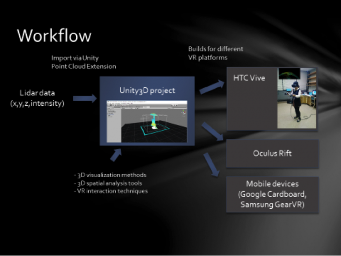
Reading Assignment
Reading Assignment
Finally, we would like you to read another article that discusses, from a more theoretical perspective, the role that using the landscape itself (especially the local landscape someone may be used to) as a means of communication. As an example, we have two projects that deal with VR and climate change. Both projects provide an opportunity to think through the options we have to communicate with people about how climate change may change their local environments, as well as what sustainable living can look like. The article is written by Stephen Sheppard and has just been published in Landscape and Urban Planning. You can download the article Making climate change visible: A critical role for landscape professionals [194] using Science Direct, through the Penn State Libraries. You may need to log in using your Penn State Access Account user id and password when you follow the link.
If you need to search for the article, the complete information is:
Journal title and issue: Landscape and Urban Planning 142 (2015) 95–105
Article title: Making climate change visible: A critical role for landscape professionals
Author: Stephen R.J. Sheppard
Deliverables
Deliverables
There are two deliverables for this lesson.
Deliverable 1: Article Reflection After reading the article by Sheppard provide a 500-word max write up reflecting on a potential paradigm shift that 3D modeling and VR induce for communicating and understanding environmental change. Guiding questions:
- What role does/can the local landscape play for communicating environmental/climate change?
- Which role do current developments in 3D modeling and VR play in allowing for an in-my-own-backyard?
| Criteria | Full Marks | Half Marks | No Marks | Possible Points |
|---|---|---|---|---|
| Write up clearly communicates how the local landscape can improve communicating environmental change. | 2 | 1 | 0 | 2 |
| Write up clearly communicates how 3D modeling and VR can improve communicating environmental change. | 3 | 1.5 | 0 | 3 |
| Write up is well thought out, organized, contains some theoretical considerations and clearly communicates why or why not this article is an example of a paradigm shift in the geospatial sciences. | 4 | 2 | 0 | 4 |
| The document is grammatically correct, typo-free, and cited where necessary. | 1 | 0.5 | 0 | 1 |
| Total Points: 10 |
Deliverable 2: Reflection Paper: Write a 750-word max reflection on the course discussing your perspective on 3D modeling and VR for the future of the geospatial sciences. Guiding questions:
- What do you consider the most exciting development in 3D modeling and VR for geospatial sciences?
- Which technology will have the greatest impact or geospatial sciences?
- Do you think that VR or AR/MR will be the dominant technology five years from now?
- Can you name three issues that are still left to be solved in current VR technology?
| Criteria | Full Marks | Half Marks | No Marks | Possible Points |
|---|---|---|---|---|
| Write up clearly communicates student’s perspective on the potential and/or pitfalls of 3D modeling and VR for geospatial sciences. | 4 | 2 | 0 | 4 |
| Write up clearly identifies key technologies in the area of 3D modeling and VR most important for geospatial sciences. | 4 | 2 | 0 | 4 |
| Write up is well thought out, organized, contains some theoretical considerations and clearly communicates why or why not this article is an example of a paradigm shift in the geospatial sciences. | 6 | 3 | 0 | 6 |
| The document is grammatically correct, typo-free, and cited where necessary. | 1 | 0.5 | 0 | 1 |
| Total Points:15 |
Summary and Tasks Reminder
Summary and Tasks Reminder
Lesson 10 provided a short outlook on how 3D modeling and VR have the potential to change how we communicate environmental change. Discussing Sheppard's article is one example of how researchers start to add theory to the technological developments that are happening. The video of the historic campus project provided a glimpse of how realistic 3D models can become with off-the-shelf software opening new possibilities for communicating with a wide audience. The Thrinukagigur example shows that immersive technologies will have an impact on a wide spectrum of geo-spatial sciences and that we are finally in the position to realize virtual field trips.
Reminder - Complete all of the Lesson 10 tasks!
You have reached the end of Lesson 10! Double-check the to-do list on the Lesson 10 Overview page to make sure you have completed all of the activities listed there. Congratulation! You have finished this course!
Undergrad
Undergrad Syllabus
Syllabus: Undergrad Course
GEOG 497: 3D Modeling and Virtual Reality
Spring 2022
It is essential that you read this entire Syllabus document as well as the material covered in the Course Orientation. Together these serve as our course "contract."
Instructor

Instructor: Mahda M. Bagher, PhD
Office: Remote
Department of Geography, College of Earth and Mineral Sciences, The Pennsylvania State University
- E-mail: mmm6749@psu.edu [195]. Please use the course e-mail system (see the Inbox in Canvas).
- Office Hours: Fridays 12:00 PM-2: 00 PM and by appointment via Zoom
NOTE: I will read and respond to e-mail and discussion forums Frequently.
Class Support Services
Penn State Online [196] offers online tutoring to World Campus students in math, writing, and some business classes. Tutoring and guided study groups for residential students are available through Penn State Learning [197].
Course Overview
Description: 3D Modeling and VR for the Geospatial Sciences is an introductory-level science course that introduces students to emerging topics at the interface of concepts and tools that capture/sense environmental information (e.g., LiDAR) and concepts/tools that allow for immersive access to geospatial information (e.g., HTC Vive). The course offers a high-level perspective on the major challenges and opportunities facing the development of current 3D technologies, differences between classic modeling and procedural rule-based modeling, the development of VR technologies, the role of game engines in the geospatial sciences. Topics that will be covered include an introduction to the 3D Modeling and 3D sensing technologies, 360 degree cameras, VR apps and tools, workflows how to integrate environmental information into VR environments, an introduction to procedural rule modeling, hands-on experience in creating 3D models of Penn State Campus, the creation of a virtual Penn State Campus, accessing and exploring a virtual campus in Unity (game engine), and the export of flyovers to platforms such as YouTube 360.
Prerequisites and concurrent courses: None.
Course Objectives
When students successfully complete this course, they will be prepared to:
- Understand and apply the concepts of 3D modeling and VR, they will be in a position to distinguish concepts such as virtual, mixed, and augmented reality.
- Explain and implement workflows to created 3D content from existing and historic and future environments.
- Use a variety of software solutions for 3D model creation such as SketchUp, CityEngine (theoretical), Unity.
- Understand the emerging possibilities of environmentally sensed information.
- Create 3D models and make them accessible in an interactive way through the use of game engines. Evaluate scenarios for the future of food considering resilience in the context of climate change, human population growth and socio-economic, and cultural factors.
Expectations
On average, most students spend 12-15 hours per week working on course assignments. Your workload may be more or less depending on your study habits.
I have worked hard to make this the most effective and convenient educational experience possible. The Internet may still be a novel learning environment for you, but in one sense it is no different from a traditional college class: how much and how well you learn is ultimately up to you. You will succeed if you are diligent about keeping up with the class schedule and if you take advantage of opportunities to communicate with me as well as with your fellow students.
Specific learning objectives for each lesson and project are detailed within each lesson. The class schedule is published under the Calendar tab in Canvas (the course management system used for this course).
Required Course Materials
Required textbooks: None
Recommended textbooks:
There are numerous books relevant to the course content. Resources are added throughout the course allowing students to follow up on specific topics.
Required materials:
D-scope Pro Google Cardboard Kit with Straps may be purchased online [198].
Online lesson content
All other materials needed for this course are presented online through our course website and in Canvas. In order to access the online materials, you need to have an active Penn State Access Account user ID and password (used to access the online course resources). If you have any questions about obtaining or activating your Penn State Access Account, please contact the World Campus Helpdesk [199].
Assessment: Assignments, Quizzes, and Exams
This course relies on a variety of methods to assess and evaluate student learning, including:
- Practical assignments - Assignments are required for each module that require students to demonstrate their understanding of topics and processes presented in each module.
- Reflective writing assignments - These writing assignments ask students to reflect on various aspects of the topics and technologies presented in the course.
- Participation - Class participation is important. Students will be expected to join the discussions on topics related to the course.
Citation and Reference Style
I personally prefer APA as a citation style but as long as you are complete and consistent you may choose any style.
It is important that your work is submitted in the proper format to the appropriate Canvas Assignment or Discussion Forum and by the designated due date. I strongly advise that you not wait until the last minute to complete these assignments—give yourself time to ask questions, think things over, and chat with others. You will learn more, do better...and be happier!
Due dates for all assignments are posted on the mini-syllabus and course calendar in Canvas.
Grading
| Assignments | Percent of Grade |
|---|---|
| Practical assignments | 60% |
| Reflective writing assignments | 30% |
| Participation | 10% |
| Total | 100% |
I will use the Canvas gradebook to keep track of your grades. You can see your grades in the Grades page of Canvas. Overall course grades will be determined as follows. Percentages refer to the proportion of all possible points earned.
| Letter Grade | Percentages |
|---|---|
| A | 93 - 100 % |
| A- | 90 - 92.9 % |
| B+ | 87 - 89.9 % |
| B | 83 - 86.9 % |
| B- | 80 - 82.9% |
| C+ | 77 - 79.9 % |
| C | 70 - 76.9 % |
| D | 60 - 69.9 % |
| F | < 60 % |
| X |
Unsatisfactory (student did not participate) |
Curve
I am not planning to curve grades.
Late Policy
I do not accept any "late work." In exceptional circumstances, you should contact me. The earlier you contact me to request a late submission, the better. Requests will be considered on a case-by-case basis. Generally, late assignments will be assessed a penalty of at least 25% and will not be accepted more than one week after the original due date.
GEOG 497 Course Schedule
![]() Printable Schedule [200]
Printable Schedule [200]
Below you will find a summary of the primary learning activities for this course and the associated time frames. This course is 15 weeks in length, including an orientation. See our Calendar in Canvas for specific lesson time frames and assignment due dates.
Weekly schedule: Lessons open on Mondays. The close date might vary depending on the course difficulty. Initial discussions posts are due on Saturday, with all discussion comments due by Tuesday. All other assignments are due on Sundays. I expect you to participate in the online discussion forums as they count toward your participation grade.
NOTE: See the CANVAS Calendar tab for a full semester calendar of events.
| Date: | Week 1 |
|---|---|
| Topics: |
|
| Readings: |
|
| Assignments: |
|
| Date: | Week 2 |
|---|---|
| Topics: |
|
| Readings: |
|
| Assignments: |
|
| Date: | Week 3 |
|---|---|
| Topics: |
|
| Readings: |
|
| Assignments: |
|
| Date: | Week 4 |
|---|---|
| Topics: |
|
| Readings: |
|
| Assignments: |
|
| Date: | Week 5 |
|---|---|
| Topics: |
|
| Readings: |
|
| Assignments: |
|
| Date: | Week 6 |
|---|---|
| Topics: |
|
| Readings: |
|
| Assignments: |
|
| Date: | Week 7 |
|---|---|
| Topics: |
|
| Readings: |
|
| Assignments: |
|
| Date: | Week 8 |
|---|---|
| Topics: |
|
| Readings: |
|
| Assignments: |
|
| Date: | Week 9 |
|---|---|
| Topics: |
|
| Readings: |
|
| Assignments: |
|
| Date: | Week 10 |
|---|---|
| Topics: |
|
| Readings: |
|
| Assignments: |
|
| Date: | Week 11 |
|---|---|
| Topics: |
|
| Readings: |
|
| Assignments: |
|
| Date: | Week 12 |
|---|---|
| Topics: |
|
| Readings: |
|
| Assignments: |
|
| Date: | Week 13 |
|---|---|
| Topics: |
|
| Readings: |
|
| Assignments: |
|
| Date: | Week 14 |
|---|---|
| Topics: |
|
| Readings: |
|
| Assignments: |
|
| Date: | Week 15 |
|---|---|
| Topics: |
|
| Readings: |
|
| Assignments: |
|
Course Policies
Instructor Information - Mahda
Mahda M. Bagher
Mahda is a doctoral candidate in Geography, specializing in GIS and Immersive technologies. She is part of the team at the Center for Immersive Experiences. Her interest is in facilitating embodied learning through designing immersive learning experiences in immersive VR. she is specifically interested in research related to memory and embodied cognition in the field of education. Her main focus has been on embodiment in the context of geospatial data visualization in VR. She also works on procedural modeling, rebuilding historical data, and integrating geospatial data in VR, including LiDAR data, DEM, shapefiles, raster data, and any point clouds. She has received several awards for academic and research achievement in her graduate research, most notably the William and Amy Easterling Outstanding Graduate Research Assistant Award and the Willard Miller Award, 1st place for the Ph.D. proposal. She will be graduating in May 2022.
Lesson 4 Tasks and Deliverables
Tasks and Deliverables
Models
This assignment has three tasks associated with it. The first task will prepare you to complete the other two successfully.
Task 1: Compare the two models of Penn State’s University Park Campus
Explore the models and software websites provided below. Working through the questions will help you prepare for Tasks 2 and 3. By now these models should be familiar to you, but you may want to take some notes to help you organize your thoughts and keep everything straight.
- What are the pros and cons of procedural modeling in comparison to hands-on modeling?
- What are the layers that have been modeled in the procedural model (Model 1)?
- Click on one of the buildings or trees in Model 1. What happens? What types of information you can get from each shape?
- Can you find the name of some tree species in the procedural model (Model 1)?
- What are the differences between hands-on models and procedural models in terms of levels of detail?
Model 1 [93]
Procedural model created at ChoroPhronesis [28] Lab using ESRI CityEngine [94] and CGA Shape Grammar rules. This model is shared with you using CE WebScene. You can turn layers on and off, zoom, rotate and explore the part of campus modeled.
Video: Procedural_2015_Jade1 (00:00)
Note: This interface may take a while to load. Please be patient. To see the full-size interface with additional options click the Model 1 link [93].
Model 2 [97]
Historical campus models (1922) created at ChoroPhronesis [28] Lab using Sketchup. These models are combined in ESRI CityEngine [94] with trees and base map generated using procedural rules. This model is shared with you as a flythrough YouTube video.
Video: Penn State campus in 1922 flythrough (non-360-degree version) (2:01) This video is not narrated.
If you want to see a larger version of the video, click the Model 2 link [97]. [203]
Task 2: Start a discussion
After reviewing the models and taking notes, start a discussion on what you believe the advantages and disadvantages are for each of the approaches. Make sure that you comment on each other's posts to help each other better understand the nuances and details of each one. Remember that participation is part of your final grade, so commenting on multiple peers' posts is highly recommended. Please also make sure to use information from the reading assignment on Shape Grammars.
Post your response to the Lesson 4 Discussion (models) discussion.
Task 3: Write a one-page paper
Once you have posted your response and read through your peers' comments, synthesize your thoughts with the comments and write a one-page paper max about the different approaches.
Submitting your Deliverable
Once you are happy with your paper, upload it to the Lesson 4 Assignment: Reflection Paper.
Grading Rubric
| Criteria | Full Credit | Half Credit | No Credit | Possible Points |
|---|---|---|---|---|
| Clearly names and describes advantages and disadvantages, including time, learning curve, accessibility, applicability, flexibility, etc. | 10 pts | 5 pts | 0 pts | 10 pts |
| Names areas of application that are best suited to each of the approaches | 3 pts | 1.5 pts | 0 pts | 3 pts |
| The document is grammatically correct, typo-free, and cited where necessary | 2 pts | 1 pts | 0 pts | 2 pts |
| Total Points: 15 |
Lesson 5 Overview
Overview
In this module, you will build a 2D map of the University Park campus including buildings, trees, roads, walkways, and a digital elevation model (DEM). You will learn how to convert 2D maps to 3D presentations. Then procedural symbology that we have created for you in CityEngine will be imported and applied to the 3D map to create a realistic scene.
Learning Outcomes
By the end of this lesson, you should be able to:
- Explain options for 3D modeling within Arc GIS Pro
- Understand ArcGIS Pro's integrated 2D–3D environment (Local and Global Scenes)
- Convert a 2D map to a 3D scene
- Explain 3D symbology
- Extrude features to 3D symbology
- Find an example of a 3D CityEngine/ArcGIS Pro model: campus model
- Compare procedural modeling rules (.cga) vs procedural rule package (*.rpk)
- Create a 3D model of elevation (DEM)
- Create a 3D scene from a 2D building footprints of campus-based on the DEM
- Employ a procedural rule symbology based on the rule package
- Link procedural rule symbology to attributes table
- Distinguish static modeling from procedural modeling
- Restructure the map and represent the 3D scene based on the imported model
Lesson Roadmap
| To Read |
|
|---|---|
| To Do |
|
Questions?
If you have any questions, please post them to our "General and Technical Questions" discussion (not e-mail). I will check that discussion forum daily to respond. While you are there, feel free to post your own responses if you, too, are able to help out a classmate.
Lesson 5 Tasks and Deliverables
Tasks and Deliverables
This Lesson tasks have 4 parts.
Part 1: Participate in a Discussion
Please reflect on your 3D modeling experience, using ArcGIS Pro; anything you learned or any problems that you faced while doing your assignment as well as anything that you explored on your own and added to your 3D modeling experience.
Instructions
Please use Lesson 5 Discussion (Reflection) to post your response to reflect on the options provided above and reply to at least two of your peer's contributions.
Please remember that active participation is part of your grade for the course.
Due Dates
Your post is due Saturday to give your peers time to comment. All comments are due by Tuesday at 11:59 p.m.
Part 2:Assignment: Reflection Paper
Instructions:
Once you have posted your response to the discussion and read through your peers' comments, write a one-page reflection paper on your experience in 3D modeling with the following deliverables as proof that you have completed and understood the process of 3D modeling for Campus.
Due Dates
Your assignment is due on Tuesday at 11:59 p.m.
Submitting Your Deliverables
Please submit your completed paper and deliverables to the Lesson 5 Graded Assignments.
Grading Rubric
| Criteria | Full Credit | Half Credit | No Credit | Possible Points |
|---|---|---|---|---|
| Paper clearly communicates the student's experience developing the 3D model in ArcGIS Pro | 5 pts | 2.5 pts | 0 pts | 5 pts |
| The paper is well thought out, organized, contains evidence that student read and reflected on their peer's comments | 4 pts | 2 pts | 0 pts | 4 pts |
| The document is grammatically correct, typo-free, and cited where necessary | 1 pts | .5 pts | 0 pts | 1 pt |
| Total Points: 10 |
Part 3: Assignment: ArcGIS Pro
If you followed the directions as you were working through this lesson, you should already have most of the last part done.
If you haven't already submitted your deliverable for this part, please do it now. You can paste your screenshots into one file or zip all of the PDFs and upload that. Task 2 will need to be a PDF, so either way, you will have two files to zip.
- Task 1: a screenshot of all layers symbolized for UP Campus (end of Section 2)
- Task 2: print a PDF map of Smoothed_DEM Layer with a legend showing the minimum and maximum elevation (end of Section 3).
Grading Rubric
| Criteria | Full Credit | No Credit | Possible Points |
|---|---|---|---|
| Task 1: Screenshot of all layers symbolized for UP Campus correct and present | 3 pt | 0 pts | 3 pt |
| Task 2: PDF map of Smoothed_DEM Layer with a legend showing the minimum and maximum elevation correct and present | 5 pt | 0 pts | 5 pt |
| Total Points:8 |
Part 4: Assignment: 3D Campus
- Task 3: print a PDF map of your 3D campus with realistic facades and trees or simply create a screenshot (end of Section 5.3)
- Task 4: print a PDF map of your 3D campus with schematic facades and analytical trees or simply create a screenshot (end of Section 5.4)
Grading Rubric Criteria Full Credit No Credit Possible Points Task 3: PDF map of your 3D campus with realistic facades and trees or simply create a screenshot correct and present5 pt 0 pts 5 pt Task 4: PDF map of your 3D campus with schematic facades and analytical trees or simply create a screenshot correct and present 5 pt 0 pts 5 pt Total Points: 10
Lesson 6 Tasks and Deliverables
Tasks and Deliverables
Assignment
This assignment has 4 parts, but if you followed the directions as you were working through this lesson, you should already have most of the first part done.
Part 1: Submit Your Deliverables to Lesson 6 Assignment: 3D Spatial Analysis
If you haven't already submitted your deliverable for this part, please do it now. You need to turn in all four of them to receive full credit. You can paste your screenshots into one file, or zip all of the PDFs and upload that. Make sure you label all of your tasks as shown below.
- Task 1: Screenshot of flooded Old Main (End of Section 1).
- Task 2: Screenshot of Campus with gradual symbology of SunShadow_January1 (End of Section 2.2)
- Task 3: Screenshot of ground shadow surface of Nursing Sciences Building (End of Section 2.3)
- Task 4: Screenshot of attributes of ground shadow surface of Nursing Sciences Building (End of Section 2.3)
Grading Rubric Criteria Full Credit No Credit Possible Points Task 1: Screenshot of flooded Old Main 4 pts 0 pts 4 pts Task 2: Screenshot of Campus with gradual symbology of SunShadow_January1 2 pts 0 pts 2 pts Task 3: Screenshot of ground shadow surface of Nursing Sciences Building 2 pts 0 pts 2 pts Task 4: Screenshot of attributes of ground shadow surface of Nursing Sciences Building 2 pts 0 pts 2 pts Total Points: 10
Part 2: Participate in a Discussion
Please reflect on your 3D spatial analysis experience, using ArcGIS Pro; anything you learned or any problems that you faced while doing your assignment as well as anything that you explored on your own and added to your 3D spatial analysis experience.
Instructions
Please use Lesson 6 Discussion (Reflection) to post your response to reflect on the options provided above and reply to at least two of your peer's contributions.
Please remember that active participation is part of your grade for the course.
Due Dates
Your post is due Saturday to give your peers time to comment. All comments are due by Tuesday at 11:59 p.m.
Part 3: Submit Your Deliverable to Lesson 6 Assignment: Google Earth
Instructions
Upload "UniversityParkCampus_Shadow.kmz" to the Lesson 6 Assignment: Google Earth.
Due Dates
Please upload your assignment by Tuesday at 11:59 p.m.
| Criteria | Full Credit | Half Credit | No Credit | Total |
|---|---|---|---|---|
| The KMZ file has all three shadows | 8 pts | 4 pts | 0 pts | 8 pts |
| Total points: 8 pts |
Part 4: Write a Reflection Paper
Instructions
Once you have posted your response to the discussion and read through your peers' comments, write a one-page paper reflecting on what you learned from working through the lesson and from the interactions with your peers in the Discussion.
Due Dates
Please upload your paper by Tuesday at 11:59 p.m.
Submitting Your Deliverables
Please submit your completed paper to the Lesson 6 Assignment: Reflection Paper.
Paper Grading Rubric
| Criteria | Full Credit | Half Credit | No Credit | Possible Points |
|---|---|---|---|---|
| Paper clearly communicates the student's experience developing the 3D spatial analysis in ArcGIS Pro. | 5 pts | 2.5 pts | 0 pts | 5 pts |
| The paper is well thought out, organized, contains evidence that student read and reflected on their peers' comments. | 3 pts | 1 pts | 0 pts | 3 pts |
| The document is grammatically correct, typo-free, and cited where necessary. | 2 pts | 1 pts | 0 pts | 2 pts |
| Total Points: 10 |
Lesson 7 overview
Overview
In this and the next two lessons, you will be working with the Unity3D game engine, simply referred to as Unity throughout the rest of the course. Unity is a rather complex software system for building 3D (as well as 2D) computer games, and other 3D applications. Hence, we will only be able to scratch the surface of all the things that can be done with Unity in this course. Nevertheless, you will learn quite a few useful skills related to constructing 3D and VR applications in Unity dealing with virtual environments. Furthermore, you will become familiarized with C# programming (the main programming language used in this engine) through a series of exercises that guide you on developing your first interactive experience in a game engine.
This lesson will begin with an overview to acquaint you with the most important concepts and the interface of Unity. It will cover basic project management in Unity, the Project Editor interface, manipulation of a 3D scene, importing 3D models and other assets, and building a stand-alone Windows application from a Unity project. Moreover, you will learn how to create a very simple “roll-the-ball” 3D game using C#, which will prepare you for more advanced interaction mechanics we will be implementing in the next lessons.
Learning Outcomes
By the end of this lesson, you should be able to:
- Explain the role of interaction for 3D/VR projects and the role of game engines for enabling access to 3D models
- Create 3D projects in Unity3D, import 3D models, and understand the basic concepts and interface elements of the Unity editor
- Manipulate scenes and add script components to game objects
- Import custom Unity packages into a unity project
- Develop a basic understanding of the physics engine of Unity (e.g. gravity, collision detection)
- Run projects inside Unity and build stand-alone applications from them
- Have a basic understanding of how to make an experience come “alive” by programming behaviours for game objects
Lesson Roadmap
| To Read |
|
|---|---|
| To Do |
|
Questions?
If you have any questions, please post them to our "General and Technical Questions" discussion (not e-mail). I will check that discussion forum daily to respond. While you are there, feel free to post your own responses if you, too, are able to help out a classmate.
Lesson 7 Tasks and Deliverables
Tasks and Deliverables
Assignment 1:Unity 3D/VR Application Review
Search the web for a 3D (or VR) application/project that has been built with the help of Unity. The only restriction is that it is not one of the projects linked in the list above and not a computer game. Then write a 1-page review describing the application/project itself and what you could figure out how Unity has been used in the project. Reflect on the reasons why the developers have chosen Unity for their project. Make sure you include a link to the project's web page in your report.
| Criteria | Full Credit | Half Credit | No Credit | Possible Points |
|---|---|---|---|---|
| URL is provided, the application/project uses Unity, is not already listed on this page, and is not a game. | 2 pts | 1 pts | 0 pts | 2 pts |
| The report clearly describes the purpose of the application/project and the application itself. | 3 pts | 1.5 pts | 0 pts | 3 pts |
| The report contains thoughtful reflections on the reasons why Unity has been chosen by the developers. | 3 pts | 1.5 pts | 0 pt | 3 pts |
| The report is of the correct length, grammatically correct, typo-free, and cited where necessary. | 2 pts | 1 pts | 0 pts | 2 pt |
| Total Points: 10 |
Assignment 2: Create the walkthrough of the Old Main
To practice Unity project management, scene editing, and project building, we want you to apply the steps from this walkthrough: Using Unity to Build a Stand-Alone Windows Application [204].
Please set up a new Unity project for this assignment. Then follow the steps from the walkthrough to add the building model to the scene, make sure that the lighting source and camera are placed in a reasonable way relative to the building model, and make the camera keyboard controlled. In the end, build a stand-alone Windows application from your project.
Deliverable 1
Three screenshots should be taken in Play(!) mode showing the entire Unity editor window. Each screenshot should show the building from a different perspective. The keyboard control of the camera will allow you to navigate the camera around to achieve this.
Deliverable 2
Uploading the zip file of the Windows stand-alone application you built (consisting of both the .exe file and the ..._Data folder) or a link to the uploaded zip file on clouds such as OneDrive or Dropbox.
| Criteria | Ratings | Pts | ||
|---|---|---|---|---|
|
This criterion is linked to a Learning OutcomeThree screenshots in Play(!) mode showing the building from three different perspectives. |
|
2 pts |
||
|
This criterion is linked to a Learning OutcomeLight source and camera are placed in a reasonable way relative to the building. |
|
2 pts |
||
|
This criterion is linked to a Learning OutcomeExtendedFlycam script for keyboard control has been applied correctly. |
|
2 pts |
||
|
This criterion is linked to a Learning OutcomeWorking Windows stand-alone application. |
|
4 pts |
||
|
Total Points: 10 |
||||
Assignment 3: “Roll-the-ball” Game
The homework assignment for this lesson is to report on what you have done in this lecture. The assignment has two tasks and deliverables with different submission deadlines, all in week 8, as detailed below. Successful delivery of the two tasks is sufficient to earn the full mark on this assignment. However, for efforts that go "above & beyond" by improving the roll-the-ball game, e.g. create a more complex play area -like a maze- instead of the box, and/or make the main camera follow the movement of the ball, you could be awarded one point if you fall short on any of the other criteria.
To help with the last suggested extra functionality, use the following script and attach it to the main camera:
using System.Collections;
using System.Collections.Generic;
using UnityEngine;

public class FollowBall : MonoBehaviour
{
    // reference to the ball game object
    public GameObject Ball;

    // a vector3 to hold the distance between the camera and the ball
    public Vector3 Distance;

    // Start is called once before the first frame update
    void Start()
    {
        // assign the ball game object
        Ball = GameObject.Find("Ball");

        //calculate the distance between the camera and the ball at the beginning of the game
        Distance = gameObject.transform.position - Ball.transform.position;
    }
    // This called after the Update finishes
    void LateUpdate()
    {
        // after each frame set the camera position, to the position of the ball plus the original distance between the camera and the ball
// replace the ??? with your solution
        gameObject.transform.position = ???;
    }
}
If you follow the detailed instructions provided in this lecture, you should be able to have a fully working roll-the-ball game.
Deliverable 1: Create a unity package of your game and submit it to the appropriate Lesson 7 Assignment.
You can do this by simply going to the Assets in the top menu and then selecting “Export Package”.
Make sure all the folders and files of your project are checked and included in the package you export (you can test this and import your package in a new Unity project to see if it runs).
If you choose to implement the functionality of the main camera to follow the ball movement, please explain your solution as a comment in your script. You can add comments (texts in green) in C# by using “//”.
Helpful advice:
We highly recommend that, while working on the different tasks for this assignment, you frequently create backup copies of your Unity project folder so that you can go back to a previous version of your project if something should go wrong.
| Criteria | Full Credit | Half Credit | No Credit | Possible Points |
|---|---|---|---|---|
| Your game runs smoothly and as intended without any errors or strange behavior | 6 pts | 3 pts | 0 pt | 6 pts |
| Your project is complete and has all the required functionalities (coin rotation, collection, and sound effect). | 3 pts | 1.5 pts | 0 pt | 3 pts |
| Your Unity package has a proper folder structure, and all the files have meaningful names like it was done in the instructions | 1 pt | .5 pts | 0 pts | 1 pt |
| Total Points: 10 |