We've just shown that the 2nd relationship between a and a' may be an extreme, but we don't know yet if this relation will result in maximized or minimized power. In order to better understand this, we have to look at the second derivative of d2f / da2.
Check the second derivative...
...from the first derivative...
...and the first derivative of eqn. (2a.30) ...
Remember the first equation (2a.30) equated the pressure differences. We now also have its first derivative, and we will take its second derivative as well and obtain:
Now we use all of the above relations in the second deriviative:
Assuming that the 1st derivative is equal to 0, we know that:
Thus, we can indeed find that …
Transcript: Maximum
If this is larger than zero, this last term here is less than zero. Agreed? 2(1-a) has a minus here. 2 is larger than zero. 1-a larger than zero. Lambda r square larger than zero. That's 1+squared larger than zero. Larger, larger, (1-2a), a is small enough, larger than zero. da'/da, I just looked at it. Larger than zero. So that's all larger than zero. There's the minus sign that makes it smaller than zero. This is all smaller than zero. So we can say at this point, indeed, the second derivative df by da square is less than zero. With the first derivative being equal to zero, second derivative less than zero, it means that we were really looking for a maximum in the power coefficient. That's all we wanted. That's probably one of the, most painful things that we're going to in the whole class, but it's in no text book. That's why I like to do that with you. So you know exactly where it comes from. Won't be everything like this. I promise.
So far we have eqns. (2a.30) and (2a.32), for a and a'. Equation (2a.30) was a result of equating the pressure drop across the disk:
And equation (2a.32) from maximizing the integral for the pressure coefficient:
Now we have 2 equations and 2 unknowns. We can take a' from eqn. (2a.32), which is a sole function of a and plug it into eqn. (2a.30) to find an explicit relation for a.
That gives us now the axial inductor induction factor a as a function of λr , which is scaled tip speed ratio, along the blade for maximum power.
Now, what is the actual CP,Max?
We take the derivitive d/da of boxed equation (2a.42) above and obtain:
Now take eqns. (2a.32), (2a.42), and (2a.44) in the relation for CP,max, and we get the following:
At the root where λr = 0, this will define the lower bound of the integral of CP,max with respect to a.
For the upper bound at the tip where λr becomes equal to the actual tip speed ratio λ, it defines the upper bound for a.
Transcript: Upper and Lower Bounds
If lambda r is zero, how does the right hand side become zero? There are two options. One of the factors has to zero, right? a=1 doesn't work for us. a=1/4 yes that's the one that's going to make it zero. That defines here now the lower bound of the integral. So a1=1/4 or 0.25 For the upper bound at the tip, where lambda r becomes equal to the actual tip speed ratio, lambda, it defines the upper bound for a and that is what? So this becomes lambda square. I can look again at equation 3. And that's not an easy equation to solve for a. So we'll do that numerically.
In the table that you see here, given different lambdas, it solves equation 3 for the appropriate upper integration bound, which is a2, and then gives you the power coefficient that is associated with it. So we can look at this table and say, depending on the tip speed ration -the tip speed ratio was tip speed divided by incoming wind speed- what's the maximum power coefficient that you get? Out of all this messy analysis. Betz limit is 0.593 something, 16/27 is the exact answer. So you can see here clearly as you go up in tip speed ratio, you're getting fairly close to the Betz limit. In other words, the quicker the rotor spins, the closer you get to the Betz limit.
Think about me being a 2-bladed rotor. And I rotate very slowly, no tip speed ratio. There's a lot of mass flow passing through the rotor disk area that the blades do not work on. It's not surprising that if the tip speed ratio is small, you do not get much power. In fact, in the limit, I'm standing still, there's no torque being produced. There's no wake change in angle of momentum associated with that. But as I move quicker and quicker in rotor speed, in a given time, the blades they work on more mass flow that passes through the rotor disk area. As a consequence the power coefficient is going to go up. What is important here is to note that you get fairly close to the Betz limit with a tip speed ratio of 10 and not 1000. That's important.
The table below provides different values for the tip speed ratio, λ, and solves eqn. (2a.42) for the appropriate upper integration bound, a2. It then provides the associated maximum power coefficient. Note that the quicker the rotor spins (λ increases), the closer it gets to the Betz limit.
| λ | a2 | CP,max |
|---|---|---|
| 0.5 | 0.2983 | 0.289 |
| 1.0 | 0.3170 | 0.416 |
| 1.5 | 0.3245 | 0.477 |
| 2.0 | 0.3279 | 0.511 |
| 2.5 | 0.3297 | 0.533 |
| 5.0 | 0.3324 | 0.570 |
| 7.5 | 0.3329 | 0.581 |
| 10.0 | 0.3330 | 0.585 |
Let us get back to the integral for Cp,max:
If we use the transformation x = 1- 3a and its derivative dx/da = -3 we obtain:
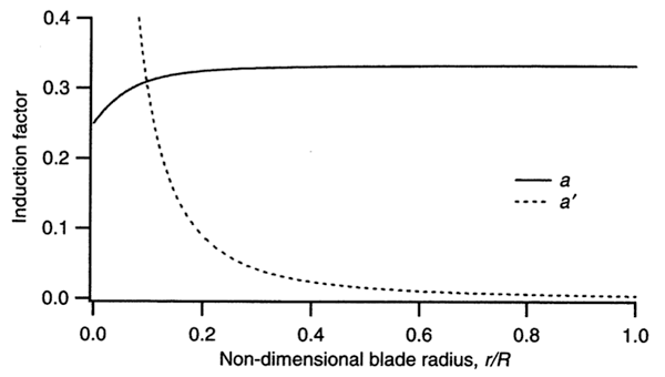
If we use this to look at the distribution, we find the induction factors a and a' as functions of the local tip speed ratio, λr, for maximum power for an example reference case of a tip speed ratio that equals 7.5.
Let us recall these numbers...
The axial induction factor where u is the axial velocity of the actuator or rotor disk, and V0 is the wind speed.
where Ω is the rotor speed.
And for the optimum case
The graph below (Fig. 2a-10) illustrates this distribution. Keep in mind that this is for a specific tip speed ratio that is fairly high at 7.5. The graph shows a and a' versus the radial position along the blade (multipy this number by the tip speed ratio 7.5. to get λr.)
The solid line represents the axial induction factor a. At the root where r or λr equals zero, the induction factor a is 0.25, and it approaches the ideal value of 1/3 towards the tip.
The dotted line represents the angular induction factor a'. In the relationship , a approaches 1/3 when a' goes to zero. Out at the tip the effect or the loss due to rotation becomes zero, and a approaches indeed the Betz limit. However, when a becomes close to 1/4, as it does at the root, we're dividing by zero and a' actually has a singularity.
Video question: In Fig. 2a-10, why does a' have a singularity?
Transcript: a' singularity
Now if you fix the tip speed ratio, the highest rotation and where you work most is out at the tip, but as you go inboard, the rotational speed becomes lesser and lesser. However, in rotor disk theory, you still have to add the swirl to the flow inboard. However, that swirl the local little omega, has a rather big portion of the actual velocity at a more inboard station. So you have capitol omega here and you add the swirl, little omega, but down here you have capitol omega times r/r, so the little omega that's acting there is larger to the actual rotation. Or another analogy, you just say well along the blade I'm sweeping over a range of tip speed ratios and you get the closest match to the Betz limit out at the tip and inboard it's less than that. Just because the local tip speed ratio is smaller there.
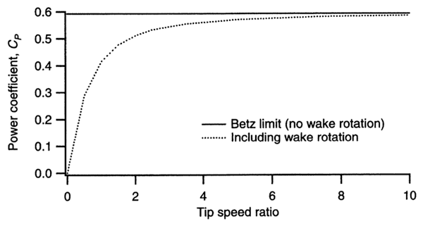
The plot below (Fig. 2a-11) illustrates the maximum power we can get including the wake rotation. We have the tip speed ratio as a free parameter λ, which equals the velocity at the tip Ω • R, divided by the wind speed V0 :
We're plotting power coefficient versus tip speed ratio. The solid line represents actuator disk theory, or the the Betz limit, which is 16/27 or approximately equal to 0.593. This is the maximum you can acheive. If your tip speed ratio is 0, the power will be zero. As you increase the tip speed ratio, the power coefficient gets closer to the Betz limit.
Video question: Is there an ideal tip speed ratio?
Transcript: Max Power
Tip speed ratio is the ratio of a tip speed to the incoming wind speed. How fast or how quick does a wind turbine have spin in order to get close to the Betz limit? Looks like from this plot, the tip speed ratio doesn't have to be 100 or 1000. This is good news. Because as you can see even for a tip speed ratio of about 5, you're already at 0.57 or so, getting pretty close to the Betz limit for a fairly low tip speed ratio. If you look at a wind turbine blade that's about 40 meters long, it weighs between 8000 and 9000 pounds. So if you double the rotor speed the centrifugal force goes with the square of the rotor speed, so that's immense. If you would have to go from 5 to 10, you're centrifugal force of this 8000 pounds that spins around gets multiplied by a factor of 4. That's significant. You don't want to do that, you want to get by with as small of a tip speed ratio as you can. Wind turbine noise is proportional between the 5th and 6th power of the tip speed. That's enormous. Any reduction in tip speed because it goes at least to the fifth power, reduces the noise significantly. And that is why for most onshore wind turbines a tip speed ratio of 4 is pretty common. Offshore in European developments in the north sea, they spin the rotors quicker. Nobody cares about the noise. But they would never go up to 10 because of structural considerations.
Validity of the Rotor Disk Model
Parameters:
The two relations between a and a':
Eliminate the λr2 by subtracting the two equations from one another and you'll find:
As we approach locally the ideal axial induction factor of a = 1/3, a' naturally goes to zero. It will also do this for high tip speed ratios. An interesting twist is that the effects of wake rotation are smallest for a quickly spinning rotor. This seems counter-intuitive at first as the loss due to wake rotation is related to the 'swirl' that's being added to the downstream flow.
In general, the higher the rotor speed, the closer one approaches the limit of the uniform-flow actuator disk. And the faster the tip speed, the smaller the relation between the ω (the swirl you're adding to the wake) and the actual rotor speed Ω.
Rotor Disk Model Summary
Let us summarize a few lines about the rotor disk model:
- 1-Dimensional, Inviscid, Irrotational, Steady
- Includes Effect of Tip Speed Ratio λ = (Ω·R) / V0
- Rotor Power still remains a function of the 3-2-1 law: P = P(V03, D2, CP(λ) )
- Approaches “Betz Limit” of CP,max ≈ 0.59 for high λ
This is the essense you should you know as well as how to sketch the relative distributions of a and a' prime versus radius and for different tip speed ratios.