
Darcy’s Experiments and Darcy’s Law
In 1855, Henri Darcy, a French hydraulic engineer (Figure 24), oversaw a series of experiments aimed to understand the rates of water flow through sand layers, and their relationship to pressure loss along the flow paths. Darcy’s experiments consisted of a vertical steel column, with a water inlet at one end and an outlet at the other. The water pressure was controlled at the inlet and outlet ends of the column using reservoirs with constant water levels (Figure 25) (denoted h1 and h2). The experiments included a series of tests with different packings of river sand, and a suite of tests using the same sand pack and column, but for which the inlet and outlet pressures were varied. For part of our in-class activity this week, we will perform our own set of “Darcy Tube” experiments, and also work with the original dataset generated by Darcy in his experiments.
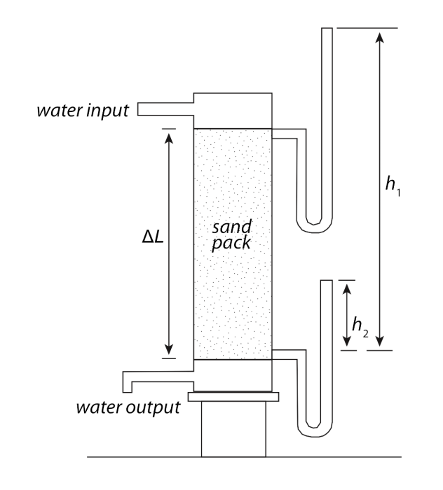
Darcy’s findings laid the foundation for the modern science of hydrogeology by quantifying the relationships between volumetric groundwater flow rate, driving forces, and aquifer properties. Specifically, Darcy’s experiments revealed proportionalities between the flux of water, Q, through the laboratory “aquifer” and different characteristics of the experimental system (refer to Figure 25 above):
(1) Q was directly proportional to the difference in water levels from inlet to outlet, h1 - h2 = Δh:
Q ∝ Δh
(2) Q was directly proportional to the cross sectional area of the tube:
Q∝ A
(3) Q was inversely proportional to the length of the column:
Q ∝ 1/ΔL
Combining these proportionalities leads to Darcy’s Law, the empirical law that describes groundwater flow:
Q = KA(Δh/ΔL)where K is a constant of proportionality that defines the water flux for a given hydraulic gradient (Δh/ΔL). The above equation can also be recast in terms of the water volume flux per unit area, Q/A (also called "Darcy flux" or "Darcy velocity" with units of length per time):
Q/A = K(Δh/ΔL)Note that in Darcy’s Law, the other terms all describe the driving forces or geometry of the experimental system; none of them would change if the sand pack in the tube were changed to gravel, silt, or another material. This is where the constant of proportionality, K, comes in: it describes the ability of the material in the column to transmit water (sound familiar?). Indeed, the constant of proportionality and hydraulic conductivity (also K) are one and the same! For example, consider the same experimental geometry, but with silt or clay in the tube rather than sand. The flow rate would be lower, and this would be described in Darcy’s Law by a smaller value of K.