4.1 Biomass Pyrolysis
The figure below shows a graphic of the four methods of thermochemical conversion of biomass, with pyrolysis highlighted. We just went over combustion and gasification, and we’ll cover direct liquefaction later on in the semester.
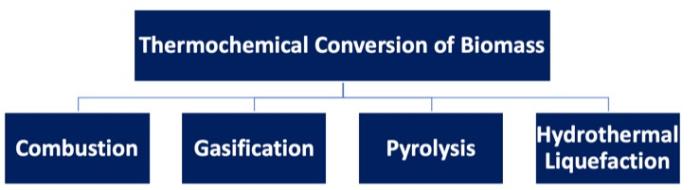
There are differences in each of the thermal processes. For combustion, the material is in an oxygen-rich atmosphere, at a very high operating temperature, with heat as the targeted output. Gasification takes place in an oxygen-lean atmosphere, with a high operating temperature and gaseous products being the main target (syngas production in most cases). Direct liquefaction (particularly hydrothermal processing) occurs in a non-oxidative atmosphere, where biomass is fed into a unit as an aqueous slurry at lower temperatures, and bio-crude in liquid form is the product.
So, what is pyrolysis? There are several definitions depending on the source, but essentially it is a thermochemical process, conducted at 400-600°C in the absence of oxygen. The process produces gases, bio-oil, and a char, and as noted in Lesson 4, is one of the first steps in gasification or combustion. The composition of the primary products made will depend on the temperature, pressure, and heating rate of the process.
There are advantages, both economical and environmental, to doing pyrolysis. They are:
- utilization of renewable resources through a carbon neutral route – environmental potential;
- utilization of waste materials such as lumber processing waste (barks, sawdust, forest thinnings, etc.), agricultural residues (straws, manure, etc.) – economic potential;
- self-sustaining energy – economic potential;
- conversion of low energy in biomass into high energy density liquid fuels – environmental & economic potentials;
- potential to produce chemicals from bio-based resources – environmental & economic potentials.
Pyrolysis was initially utilized to produce charcoal. In indigenous cultures in South America, the material was ignited and then covered with soil to reduce the oxygen available to the material – it left a high carbon material that could stabilize and enrich the soil to add nutrients ([Discussion of applications of pyrolysis], (n.d.), Retrieved from MagnumGroup.org). It has also been used as a lighter and less volatile source of heat for cooking (i.e., “charcoal” grills) in countries where electricity is not widely available and people use fuel such as this to cook with or heat their homes (Schobert, H.H., Energy, and Society: An Introduction, 2002, Taylor & Francis: New York). Not only is there a solid product, such as charcoal, but liquid products can also be produced depending on the starting material and conditions used. Historically, methanol was produced from the pyrolysis of wood.
This process for pyrolysis can also be called torrefaction. Torrefaction is typically done at relatively low pyrolysis temperatures (200-300°C) in the absence of oxygen. The feed material is heated up slowly, at less than 50°C/min, and is done over a period of hours to days – this way the volatiles are released and carbon maintain a rigid structure. In the first stage, water, which is a component that can inhibit the calorific value of a fuel, is lost. This is followed by a loss of CO, CO2, H2, and CH4, in low quantities. By doing this, approximately 70% of the mass is retained with 90% of the energy content. The solid material is hydrophobic (with little attraction to water) and can be stored for a long period of time.
Classification of pyrolysis methods
There are three types of pyrolysis: 1) conventional/slow pyrolysis, 2) fast pyrolysis, and 3) ultra-fast/flash pyrolysis. The table and figure below summarize how each method differs in temperature, residence time, heating rate, and products made.
As mentioned earlier, slow pyrolysis is typically used to modify the solid material, minimizing the oil produced. Fast pyrolysis and ultra-fast (flash) pyrolysis maximizes the gases and oil produced.
Fast pyrolysis is a rapid thermal decomposition of carbonaceous materials in the absence of oxygen at moderate to high heating rates. It is the most common of the methods, both in research and in practical use. The major product is bio-oil. Pyrolysis is an endothermic process. Along with the information listed in the table, the feedstock must be dry; of smaller particles (< 3 mm); and typically done at atmospheric temperature with rapid quenching of the products. The yields of the products are: liquid condensates – 30-60%; gases (CO, H2, CH4, CO2, and light hydrocarbons) – 15-35%; and char – 10-15%.
Ultra-fast, or flash pyrolysis is an extremely rapid thermal decomposition pyrolysis, with a high heating rate. The main products are gases and bio-oil. Heating rates can vary from 100-10,000° C/s and residence times are short in duration. The yields of the products are: liquid condensate ~10-20%; gases – 60-80%; and char – 10-15%.
| Method | Temperature (°C) |
Residence Time |
Heating rate (°C/s) |
Major products |
|---|---|---|---|---|
| Conventional/slow pyrolysis | Med-high 400-500 |
Long 5-30 min |
Low 10 |
Gases Char Bio-oil (tar) |
| Fast pyrolysis | Med-high 400-650 |
Short 0.5-2 s |
High 100 |
Bio-oil (thinner) Gases Char |
| Ultra-fast/flash pyrolysis | High 700-1000 |
Very short < 0.5 s |
Very high >500 |
Gases Bio-oil |
Credit: Boyt, R., (November 2003), Wood Pyrolysis. Retrieved from Bioenergylists.org
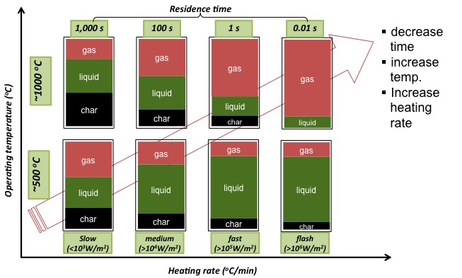
| Heating rate | Time | Temperature (ºC) | Char | Liquid | Gas |
|---|---|---|---|---|---|
| Slow (<103 W/m2) | 1000s | ~500ºC | 25% | 35% | 40% |
| Medium (>104 W/m2) | 100s | ~500ºC | 17% | 58% | 35% |
| Fast (>105 W/m2) | 1s | ~500ºC | 15% | 65% | 20% |
| Flash (>106 W/m2) | 0.01s | ~500ºC | 10% | 70% | 20% |
| Slow (<103 W/m2) | 1000s | ~1000ºC | 40% | 35% | 25% |
| Medium (>104 W/m2) | 100s | ~1000ºC | 20% | 37% | 43% |
| Fast (>105 W/m2) | 1s | ~1000ºC | 15% | 20% | 65% |
| Flash (>106 W/m2) | 0.01s | ~1000ºC | 0% | 15% | 95% |
Bio-oil Product Properties
Crude bio-oils are different from petroleum crude oils. Both can be dark and tarry with an odor, but crude bio-oils are not miscible with petro-oils. Bio-oils have high water content (20-30%); their density is heavier than water (1.10-1.25 g/mL); their heating value is ~5600-7700 Btu/lb (13-18 MJ/kg). Bio-oils have high oxygen content (35-50%), which causes high acidity (pH as low as ~2). Bio-oils are also viscous (20-1000 cp @ 40°C) and have high solid residues (up to 40%). These oils are also oxidatively unstable, so the oils can polymerize, agglomerate, or have oxidative reactions occurring in situ which lead to increased viscosity and volatility. The values in the table below compare the properties of bio-oil to petroleum-based heavy fuel oil.
| Physical Property | Bio-oil | Heavy fuel oil |
|---|---|---|
| Moisture Content | 15-30 | 0.1 |
| pH | 2.5 | -- |
| Specific gravity | 1.2 | 0.94 |
| Elemental composition (wt%) | - | - |
| C | 54-58 | 85 |
| H | 5.5-7.0 | 11 |
| O | 35-40 | 1.0 |
| N | 0-0.2 | 0.3 |
| Ash | 0-0.2 | 0.1 |
| HHV, MJ/kg | 16-19 | 40 |
| Viscosity (cp, @50°C) | 40-100 | 180 |
| Solids (wt %) | 0.2-1 | 1 |
| Distillation residue (wt%) | Up to 50 | 1 |
Credit: Czemik, S. and Bridgewater, A.V., 2004. Overview of Applications of Biomass Fast Pyrolysis, Energy Fuels 18, 590-598.
Process Considerations
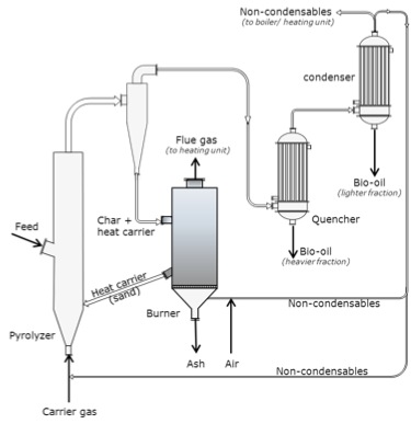
Several components are necessary for any pyrolysis unit, outside of the pyrolyzer itself. The units and how they are connected are shown in the figure below.
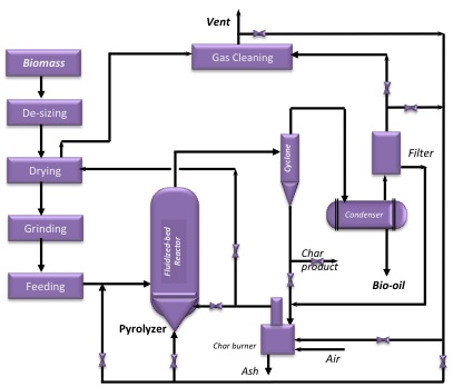
The goal of the process is to produce bio-oil from the pyrolyzer. The bio-oil that’s generated has potential as a transportation fuel after upgrading and fractionation. Some can be used for making specialty chemicals as well, especially ring-structure compounds that could be used for adhesives. The gases that are produced contain combustible components, so the gases are used to generate heat. A biochar is produced as well. Biochar can be used as a soil amendment that improves the quality of the soil, sequesters carbon, or can even be used as a carbon material as a catalyst support or activated carbon. There will also be a mineral-based material called ash once it’s been processed. Typically, the ash must be contained.
The next units to be considered are separation units. Char is solid, so it is typically separated using a cyclone or baghouse. It can be used as a catalyst for further decomposition into gases because the mineral inherent in the char as well as the carbon can catalyze the gasification reactions. The liquids and gases must also be separated. Usually, the liquids and gases must be cooled in order to separate the condensable liquids from the non-condensable gases. The liquids are then fractionated and will most likely be treated further to improve the stability of the liquids. At times, the liquid portion may plug due to heavier components. The non-condensable gases need to be cleaned of any trace amounts of liquids and can be reused if needed.
The next consideration is the heat sources for the unit. Hot flue gas is used to dry the feed. As the flue gas contains combustible gases, they can be partially combusted to provide heat. Any char that is left over is burned as a major supply of heat. And, biomass can be partially burned as another major source of heat.
Another important process to consider is the means of heat transfer. Much of it is indirect, through metal walls and tube and shell units. Direct heat transfer has to do with char and biomass burning. In the fluidized bed unit, the carrier (most often sand) brings in the heat, as the carrier is heated externally and recycled to provide heat to the pyrolyzer.
Types of Pyrolyzers
So, what types of pyrolyzers are used? The more common types are fluidized-bed pyrolyzers. The figures below show schematics of two different types. The advantages of using fluid beds are uniform temperature and good heat transfer; high bio-oil yield of up to 75%; a medium level of complexity in construction and operation; and ease of scaling up. The disadvantages of fluid beds are the requirement for small particle sizes; a large quantity of inert gases; and high operating costs. The circulating fluid bed pyrolyzer, (CFB), shown below, has similar advantages, although medium-sized particle sizes for feed are used. Disadvantages include a large quantity of heat carriers (i.e., sand); more complex operation, and high operating costs.
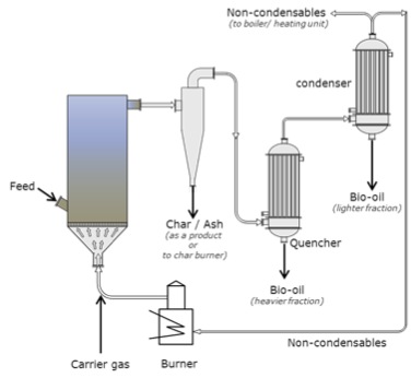
Schematic of a fluid bed with electrostatic precipitator. The carrier gas enters the fluid bed that has an intake feed. The gas then goes through a cyclone and the char and ash are removed as a product or taken to the char burner. The gas then passes through the quencher and the heavier fraction is removed as bio-oil, it then passes to the condenser where the lighter fraction is condensed as bio-oil and the non-condensable are taken to the boiler or the burner. Any gases created at the burner are used as carrier gas.
Schematic of a fluid-bed with circulating heat carrier (circulating fluid-bed (CFB) pyrolyzers. The carrier gas enters the bottom of the fluid bed through a pyrolyzer. The fluid bed also has an intake feed halfway up. The gas then goes through a cyclone and the char and heat carriers are removed and taken to a burner. The heat carriers (sand) are returned to the fluid bed/pyrolyzer. The ash is removed and flue gas is taken to the heating unit. The gases that come out of the cyclone then pass through the quencher and the heavier fraction is removed as bio-oil, it is then passed to the condenser where the lighter fraction is condensed as bio-oil, and the non-condensable is taken to the boiler or the burner. Any gases created at the burner are used as carrier gas.
Two other types of pyrolyzers are the Rotating Cone and the Auger pyrolyzers. The rotating cone creates a swirling movement of particles through a g-force. This type of pyrolyzer is compact, has a relatively simple construction and operation, and has a low heat carrier/sand requirement. However, it has a limited capacity, requires feed to be fine particles, and is difficult to scale up. Auger pyrolyzers are also compact, simple in construction, and easy to operate; they function at a lower process temperature as well (400 °C). The disadvantages of Auger pyrolyzers include long residence times, lower bio-oil yields, high char yield, and limits in scaling up due to heat transfer limits.
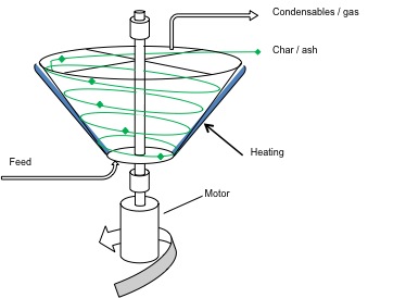
Schematic of a rotating cone pyrolyzer. The cone has feed at the bottom and heat is applied to the outside walls of the cone. A motor spins the cone and the gas/condensables come out the top as does the char/ash.
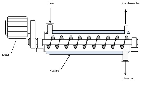
Schematic of an Auger pyrolyzer. The diagram looks like a cylinder with a corkscrew inside. A motor is attached to the rotating corkscrew. The walls of the cylinder are heated and at one end there is a feed. On the other end, there are outtake ports for condensables to come out the tops and char/ash to come out the bottom.
Bio-Oil Upgrading
As noted earlier, bio-oil has issues and must be upgraded, which means essentially processed to remove the problems. These problems include high acid content (which is corrosive), high water content, and high instability both oxidatively and thermally (which can cause unwanted solids formation).
The oils must be treated physically and chemically. Physical treatments include the removal of char via filtration and emulsification of hydrocarbons for stability. Bio-oils are also fractionated, but not before chemical treatments are done. The chemical treatments include esterification (a reaction with alcohol to form esters – this will be covered in detail when discussing biodiesel production); catalytic de-oxygenation/hydrogenation to remove oxygen and double bonds; thermal cracking for more volatile components; physical extraction; and syngas production/gasification.
Catalytic de-oxygenation/hydrogenation takes place. A catalyst is used along with hydrogen gas; specialty catalysts are used, such as sulfides and oxides of nickel, cobalt, and molybdenum. Hydrogenation is commonly used in petroleum refining for the removal of sulfur and nitrogen from crude oil and to hydrogenate the products where double bonds may have formed in processing. Catalytic processes are separate processes and use specific equipment to perform the upgrading. One problem can be that there may be components of bio-oil that may be toxic to catalysts.
Esterification reacts to the corrosive acids in bio-oils with alcohol to form esters. An ester is shown below. A discussion of the esterification reaction will be discussed in the biodiesel lesson.
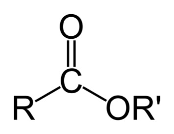
Bio-oil can also be thermally cracked and/or made into syngas through gasification. Please refer to Lesson 2 for the thermal cracking discussion and Lesson 4 for the gasification discussion. One other process that can be utilized is physical extraction, although extraction takes place due to the affinity of some of the compounds to a particular fluid. One example is the extraction of phenols. Phenols can be extracted using a sodium solution such as sodium hydroxide in water; the phenolic compounds are attracted to the sodium solution, while the less oxygenated compounds will stay in the organic solution. Again, this will be discussed in more detail in later lessons. The figure below shows a schematic of a typical processing unit to upgrade bio-oil.
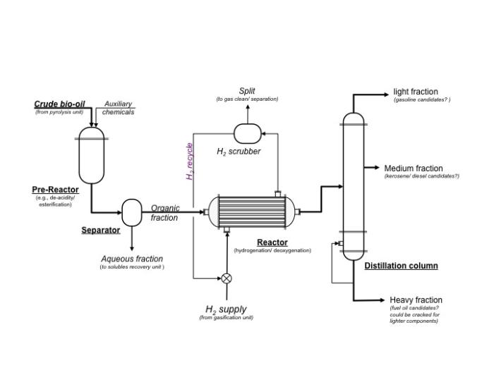
Schematic of a typical processing unit to upgrade bio-oil. Crude bio-oil and auxiliary chemicals ender the pre-reactor which does things such as de-acidify or esterify. From the pre-reactor, the crude bio-oil goes to the separator. The aqueous fraction is removed and goes to the solubles recovery unit. The organic fraction goes to the reactor where hydrogen gas is pumped in to do hydrogenation and deoxygenation. The gases are removed to a hydrogen scrubber which cleans and separates the gases. The hydrogen gas is recycled. The bio-oil then goes to a distillation column. The heavy fraction is a fuel oil candidate and could be cracked for lighter components. The medium fraction can become kerosene or a diesel candidate. The lightest fraction can become a gasoline candidate.
Biomass Pretreatment
Current methods of generating biofuels are primarily from starch or grain, and starch hydrolysis is fairly straightforward. However, because the starch feedstocks are typically food-based, the goal is to develop technologies to produce ethanol from cellulose; cellulose is obtained from lignocellulosic biomass sources and must be pretreated before breaking down into ethanol. Below is a schematic of the differences in processing for starch (current) and cellulose (emerging). Before we go any further, we will have a short tutorial on the various components of lignocellulosic biomass.
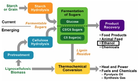
Schematic of processing differences for cellulose and starch. For starch or grain, it goes through starch hydrolysis and then the fermentation of glucose to recover the final product. The final products are food products, animal feed, ethanol, and chemicals.
For cellulose (lignocellulosic biomass) it must go through a pretreatment before entering cellulose hydrolysis and then the fermentation of carbon 5 and 6 sugars to recover the final products. The final products are food products, animal feed, ethanol, and chemicals. Any lignin residue goes through thermochemical conversion to become heat and power, and fuels and chemicals: pyrolysis oil and synthesis gas.