8.4.1a Cut and Fill Stoping
Cut and fill is a very expensive method, but is very selective. You might predict the type of deposits in which it would be employed as the principal mining method. High value metalliferous ores such as gold or silver are often mined by this, and when the high-grade ore is in veins, the high degree of selectivity of this method is a real asset.
The basic concept of cut and fill is straight forward: we mine a portion of the stope, and then we completely backfill the mined portion. The backfill may simply be broken rock, but more likely is a mix of cement and waste rock. This backfill serves to support the stresses that were originally borne by the ore, and we’ll talk more about the backfill material in a while. Deciding how much ore to recover before beginning the backfilling is an important engineering decision. If you take too much or leave the opening unsupported for too long, it will fail. If you error on the conservative side, your productivity will suffer, and the mining cost will escalate.
So, let’s take a look at one implementation of the cut and fill method. We define a stope by driving an upper and lower haulage level. This defines the height of the stope, and a height of 150’-300’ is typical. The length of the stope is running left to right in the figure below, and may be on the order of 200’-2000’. The width of the stope is going into the page, and in this drawing you cannot tell anything about the width. The width would need to be at least 6’ and may be as much as 100’.
What determines these dimensions? First, you will try to keep your stope within the mineralized zone of the orebody. Second, ground control considerations will prevent you from making the stope too large. Third, the equipment that you are using will require certain minimum dimensions. If the equipment is 8’ wide, then the narrowest dimension of the stope, which is the width, must be greater than 8’.
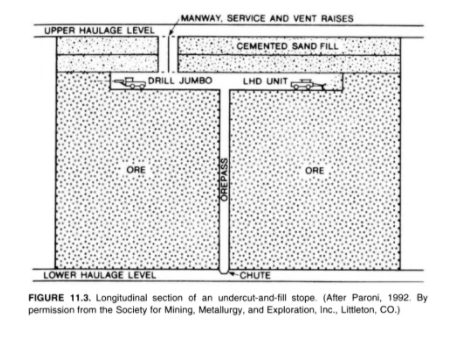
Looking at the figure, you can see the progression of mining activity. This figure is representing an undercut and fill cycle. Drifting or breast stoping is started with the jumbo drill. The holes are charged and shot, and then the LHD loads out or mucks the broken ore, and drops it down the orepass. The orepass is a raise that has been excavated for that purpose, and typically the raise will be protected with a grizzly at the top. This is done to prevent a large rock from plugging the orepass. If that happens, it is very dangerous. Someone has to go down into the orepass to drill and blast the plug. Anyway, as soon as we’ve completed mining the slice of ore, we will begin to backfill. The height of the slice that we take will be determined by ground control considerations, and is likely to be at least 10’ but no more than 30’. The ore will be collected at the lower haulage level and taken out of the mine. It is likely that mine trucks will be used, and there may or may not be a hoist involved in the operation.
Ok, now that you have the basic concept, there are a few variations. The figure illustrates mining moving downward, which we know as underhand stoping, and, in this case, we modified the term cut and fill to undercut and fill. In some deposits, we may choose to mine the orebody in an upward direction, which we know as overhand stoping. In this case, we modified the term cut and fill to overhand cut and fill. Finally, there are times when we progress in small slices, with an ultimate direction of up or down in the deposit; but, in this case, we often call it drift and fill. Don’t stress over the nuances of these terms, but you should already know what we mean by: overhand, underhand, and breast stoping; undercut and fill; and overhand cut and fill.
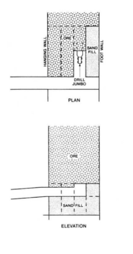
Here, below, is a deposit in which the ore is so weak that we cannot take a slice across the entire length of the stope, and have to take it in small slices – backfilling each as we go. This is an example of a drift and fill operation.
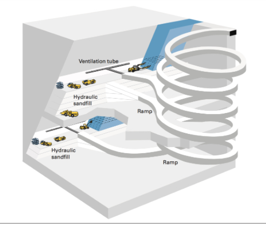
Next, we have a diagram of a modern cut and fill operation with a ramp in place. If you were to go into the underground gold mines in Nevada, for example, you would see mines similar to this. This particular example is using overhand cut and fill, but you will also see undercut and fill in practice there.
Fill and Backfilling
Significant research has gone into the development of fill materials, the engineering practices to use backfill, and the design of cut and fill mines. Let’s take a closer look at the fill.
Historically, waste rock mined underground, tailings from the prep plant, or rock quarried from a nearby location on the surface were used as backfill. In the former two instances, backfilling serves a secondary purpose of disposing of useless byproducts. Rather than accumulate large mountains of tailings on the surface near the mineral processing plant, we can use them productively in the active mine. Over the years, the practice of adding cement to these raw materials was incorporated into most operations. The addition of cement allows for a stronger backfill to be formulated and placed. It also can be used to provide a smooth working surface. If you are overhand stoping, for example, your equipment will be working from the last backfilled surface. By adding extra cement to this top layer, the equipment and miners will work more productively and safely.
Engineers generally consider three types of fill
- Hydraulic fill: tailings (55 - 70% solids) and 3-4% cement, with a 10% cement mix to top off the fill (smooth hard surface). Pumped underground as a slurry.
- Paste fill: unclassified tailings (up to 88% solids) with only a few percent cement. Requires precise mix and a more expensive plant but offers a stronger backfill and the use (recycling) of a higher percentage of tailings.
- Cemented rock fill: originally waste rock was used to fill the stope, and then hydraulic fill was sprayed on top to form the working surface. Today, the cement is often added at the surface, and then the backfill is dropped down a winze.
You don’t have to memorize these three types, but I’d like you to have an approximate idea of the mix for hydraulic fill.
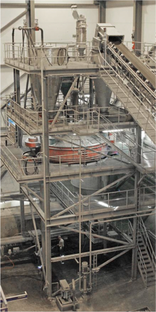
Here, below is a photo of a paste fill plant, where the tailings are dewatered and mixed with the cement, and then pumped into the mine for placement.
It is important to note that backfill can represent 10 - 20% of the mining cost, and of that cost, nearly 75% is the cost of the cement!
Cut and fill is an important mining method because it enables the recovery of high-value metal deposits in weak rock. The ability to be very selective with this further enhances its usefulness in many of these deposits, in which the spatial characteristics of the deposit require a more selective method. There is another important use of the method, and that is in pillar recovery.
I did mention earlier that often there is a significant value in the pillars that remain after the stope has been mined. In shrinkage stoping or open stoping, the crown and sill pillars as well as the pillars separating the production stopes contain significant ore. But how do you safely recover them? They are there to support the mine openings, and if you attempt to remove them, the openings will collapse. The solution is to backfill the mined-out area around the pillars. Then, with the backfill supporting the weight of the overlying rock, you can safely extract the pillars. Of course, the economics of doing so must be analyzed carefully.
This method of pillar recovery is also practiced in some metal mines employing the room and pillar method. A notable example is in the Viburnum Trend in Missouri – a famous lead-zinc mining region in the U.S. There they have roughly one million dollars of ore tied up in one pillar. Using a cut and fill approach, which is expensive, they are able to recover the pillars profitably.