A. Download the Lesson Data
My story:
As I acquired data for my project, I encountered quite a few manipulations that I had to do in order to make all the data work together. I found some data in different software formats. I found some data in different projections (undefined with no metadata to tell me what the projection was). I downloaded data in interchange formats that needed to be imported. We'll go through the process I used to bring some of the data together.
Registered Students download from ANGEL the Lesson 5/6 data (lesson5_6files.zip) to a new folder (e.g., C:\MGIS\GEOG488\Lesson5_6).
The data in this exercise are used by permission of the State College Borough Water Authority, Centre County GIS, and Meridian GeoSystems Inc.
B. Load the Basemap Data
We will be adding data from many different sources (e00 file, xy data from a GPS, Mapinfo Data by import), and first we will be transforming CAD data to the coordinate space of the Centre County basemap data.
- The basemap data are the reference layers to which we want to transform the CAD data. In ArcMap, add the buildings and streets layers to the data frame. These data are already defined as NAD 1983 State Plane Pennsylvania North (Feet).
- Rename the data frame to Basemap.
- Make sure that the projection is set for the base map data and that it is not in "Geographic Projection." CAD data cannot be aligned with non-projected data because CAD data is flat, so must the data that is used for the transform be also flat. More information before you start is available at the Esri Support Site: Transforming CAD Data and Projecting CAD Data
- Problems can arise if you are not using ArcView 9.3 or do not have the service packs up to date for 9.2 (Sp3 required)
C. Integrate CAD Data
Load Data
- The CAD drawing is the same data that you downloaded in Lesson 1, but it has been renamed to SCBWA_PGM.
- Open ArcCatalog and navigate to your Lesson5_6 folder.
- This folder should now contain the CAD drawing from lesson 1 and shapefiles for Centre County, PA. The CAD data consists of a CAD drawing file and a CAD feature dataset.
- Preview the CAD drawing in ArcCatalog. You see all of the features within all of the layers of the drawing. The symbology you see is the same as that defined in the drawing. Also notice that you are only allowed to preview the geography.
- Preview the CAD feature dataset in ArcCatalog. Notice that now the drawing is divided into CAD feature classes: points, lines, polygons, and annotation.
- Use the Identify button to identify some of the features.
- In ArcMap, insert a new data frame into your map document and name it CAD. Drag the SCBWA_PGM.dwg CAD feature dataset into ArcMap's map display area. Click OK if you get a message that the layer is missing spatial reference information.
Set Transformation
The CAD feature dataset is not in the same coordinate space as the Centre County basemap data layers. It needs to be transformed into geographic space. In ArcMap at 9.2 there are a number of ways to do this. One method is to use the georeferencing toolbar and move and manipulate the cad drawing as if it were a raster or orthophoto image file. There are a number of tools on the bar to fit the drawing to the display and rotate and move it. The final step is to click the Update Georeferencing; This will lock the CAD drawing to the geo-coordinate system and generate a Worldfile. Another method is to look at the drawings properties by right clicking in the TOC. Under the property Transformations you can set up a worldfile directly. To see all the range of ways of working with CAD Drawing transformations I suggest that you look at Esri Help File for CAD Transformations or look at it online here.
We are going to use a Worldfile, as this method is permanent, and suitable for ArcGIS 9.1 and earlier. The accuracy of the transformation in all methods depends upon the accuracy and precision of locating common points between the Cad Drawing and the feature set used as a coordinate source. Sometimes, doing this manually is more accurate than the interactive method in the georeferencing tool set.
By using a world file, the SCBWA data can be positioned in the same coordinate space as the Centre County basemap data. In the next few steps, you will create a CAD world file to apply a coordinate transformation to the CAD layer to make sure it overlays with your other data. The CAD world file is a simple text file that contains four coordinate pairs.
You will identify a pair of common control points that are easy to identify in both the CAD feature dataset and the reference dataset. It's always a good idea to use fixed features such as road intersections or corners of buildings as control points because they are unlikely to move with time. You can document this in the Metadata, too, so that people know how you derived the coordinate system.
Make a WorldFile
- You will use buildings to define your control points.
- Turn off all the layers except the Polyline layer.
- We will change the visibility to display only buildings. Double-click the SCBWA_PGM.dwg Polyline layer in the ArcMap Table of Contents. In the Layer Properties dialog, go to the Drawing Layers tab, click Disable All, then check the box next to EX_BUILDING and EX_ROAD. Click OK.
- Change the symbology of the layer so the roads and buildings show up in different colors. Open Layer Properties. Click the Symbology tab. Choose Unique Values under Categories. Choose Layer for the Value Field. Click Add All Values and change the symbols of the two values.
- Zoom in on the building that is inside the bend in the road in the Northeast corner of the layer. [See Figure 1] Zoom to the northern corner of the larger building [See Figure 2] to the extent where the coordinates do not change when you move the mouse slightly. [See Figure 3]
- Identify the x,y coordinates from the CAD data frame by holding the mouse pointer over this corner. Open a text editor such as Notepad or Wordpad and record the coordinates shown in the bottom right corner of your display window, separating the x coordinate and y coordinate with a comma. e.g., 52961.71, 46873.18.
- Now we will identify the x,y coordinates from the Basemap data frame. Activate the Basemap data frame. You will be switching back and forth between data frames. There are shortcuts to do that. The F11 key activates a selected data frame. You can also hold down the Alt key and click a data frame to activate it.
- Discover more shortcuts in the ArcGIS Desktop Help. From the Help menu, selectArcGIS Desktop Help. Click the Index tab, type shortcuts and double-click for ArcMap in the list that appears in the Help window.
- Locate the same building and zoom in on the same corner shown. You can search the streets layer for Scott Rd. and then zoom to that feature to get in the general area. Hover your mouse over the corner and enter the x,y coordinates into the text editor the same as you did above.
Tip: You can use snapping to assist with the accurate creation of the control points. Snapping requires an active session, so you will need to have an editable vector layer in the map (preferably the editable layer will serve as the snapping layer).
- Format the coordinates you just collected in your text editor as follows: cadx,cady refx,refy. The coordinate values themselves don't contain commas. There is only one space character in this file and it is between the CAD values and the reference file (Basemap) values (cadx,cady refx,refy).
- Locate a second control point. Using the same procedure you used above, obtain a second pair of control points using the building found at the intersection of Butternut St. and Water St. [See Figure 4 for a view of the building in the CAD data frame and Figure 5 for a view of the building in the Basemap data frame.]
- Remember to identify the x,y coordinates from the CAD data frame first, followed by the corresponding x,y coordinates in the Reference (Basemap) data frame.
- Add the second set of point values to the second line of the text editor so the values are in the following format (The words "cad" and "ref" are used here only to distinguish the difference between the coordinates. Do not use them in your table.):
cadx,cady refx,refy
cadx,cady refx,refy
- Save the text file as SCBWA_PGM.wld in your Lesson5_6 folder. The world file is named the same as the CAD file, so it will be applied automatically whenever it is added to ArcGIS. This file must have exactly the same name (case sensitive) or it won't be recognized as part of the CAD files.
- When you save the file, be sure the file type specified is All files or (*.*), or the text editor will append a .txt extension onto the file, making the world file unrecognizable by ArcMap.
- We will now apply the transformation. Activate the CAD data frame.
- Display the Layer Properties for SCBWA_PGM.dwg. Click the Transformations tab and check Enable Transformations.
- For World File Name, click Browse, navigate to your Lesson5_6 folder, and open SCBWA_PGM.wld.
- Click OK to close the Layer Properties dialog.
- As the two line world file rotates, re-scales, and moves the CAD data to the new coordinate space, you no longer see SCBWA_PGM.dwg displayed. You'll get to see this at the end of the next step.
This is called an affine transformation and it changes the display by scaling and rotating, it is the moving the cad drawing to be concordant with the lines in the shape file. It is important that this method of moving CAD files only uses two reference points, unlike spatial adjust or georeferencing imagery. Done as an affine transformation parallel lines stay parallel and angles are correct, the strengths of the CAD system are preserved and the drawing is fitted to geographic space. What if they do not line up exactly? Well, data integration will not solve every problem. Unless you know for certain which is correct there is no basis for changing the drawing or the shapefile. - We will now define a spatial reference. The CAD layer is now in the correct coordinate space, but you still need to define a spatial reference for the data. Be aware, however, that defining a coordinate system is not the same as changing the coordinate system. The coordinate system you specify must be that used by the data. It is the same coordinate system used by the Basemap data.
- In ArcCatalog, right-click the SCBWA_PGM.dwg CAD feature dataset and click Properties. The CAD Feature Dataset Properties dialog appears.
- Click the Spatial Reference tab.
- Click Edit. The Spatial Reference Properties dialog appears.
- Click Import. The Browse for Dataset dialog box appears.
- Browse to one of the basemap layers and click Add.
- Click Save As. The Save Coordinate System dialog appears.
- Save the file as SCBWA_PGM.prj in your Lesson5_6 folder.
- Click OK to close the Spatial Reference Properties dialog.
- Click OKto close the CAD Feature Dataset Properties.
- Confirm that your data is in the correct coordinate space. In ArcMap, insert a new Data frame named Centre_County. Add both the buildings.shp file as well as the SCBWA_PGM.dwg CAD feature dataset to your map. The data should now line up.
- Browse over the image to see how they do line up. You will see that the CAD Drawing buildings are not identical to those in the Building Feature Set. The CAD buildings are more generalized, and appear to be more out of date. These kinds of Problems are common in mixing data sets, interoperability means that we can operate with both, but should not be assumed to mean data identity.
Optional Conversion
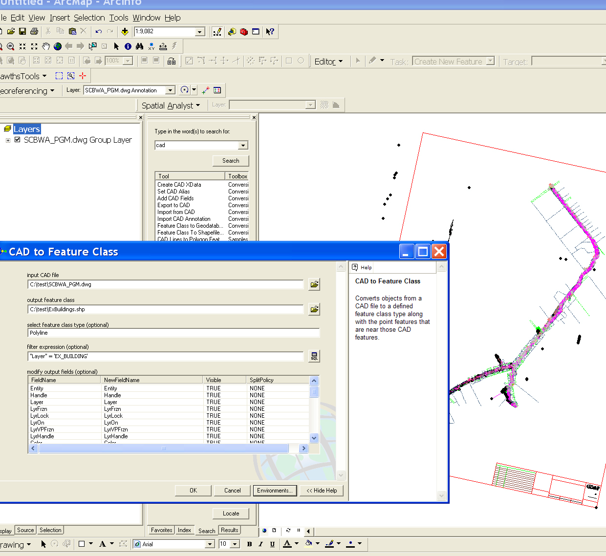
The easiest way to convert CAD files into ArcGIS shape or geodatabase is to use the CAD tool (example). Make sure to export using the data frame coordinate system, not the source, or they will revert to CAD space instead of geographic space. You will need to set the projection for the files after as the Esri tool does not support this function. With this tool you can run a selection SQL statement to choose just the features you require. If you do not do this, all the lines will end up in the same shape file. You have to repeat this action for each geometry type, point, line, polygon, annotation.
D. Integrate Coordinates from a GPS
These are a few points of interest on the Penn State Campus.
- Add the table campus_loc.txt to your Centre_County data frame.
- Click Tools > Add XY Data.
- Choose x for the X Field and y for the Y Field and click OK.
- Export the Events layer to a shapefile or feature class.
E. Integrate .e00 Files
These are school district data for Pennsylvania. Again you will see that there is no metadata and no coordinate system defined.
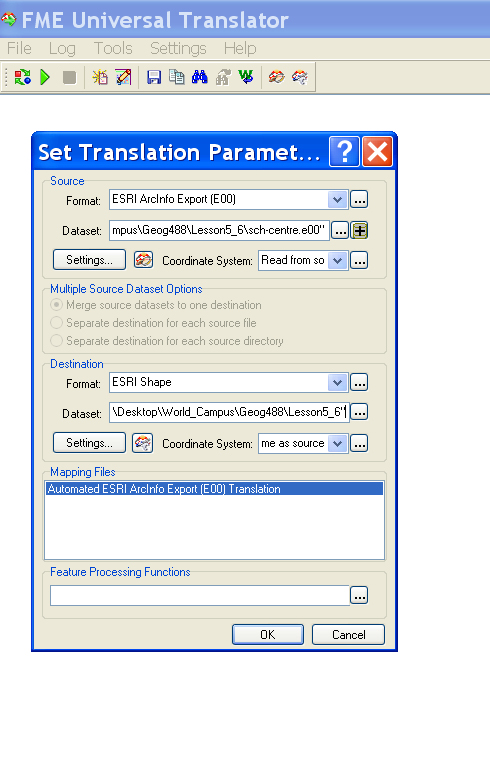
- Open the FMS Universal Translator.
- Under file menu pick Translate
- In the window set format from the format gallery to Esri e00
- Pick the data set as sch-centre.e00 from the Lesson 5_6 folder where you extracted the data
- Leave Coordinate System as read from source ...
- Choose the destination format as Esri Shapefile.
- Choose the destination dataset as a folder of your choice.
Hint e.g. Schools Example, Figure 6. - Set the destination projection to be the same as the streets, which in this case is EPSG-2271 or PA83 NF
- Run translation
- Open ArcCat and navigate to new folder.
- Delete points shapefile that were converted but are not needed
- Rename Polygon output to SchoolDist
- Change to ArcMap and add the new Shape file
- Make sure they line up with streets shapefile
- FME also supports buttons and drag drop for lots of functions. Also the translator will let you increase the density of vertices, clip to a subsection and many other functions that we do not need here.
F. Integrate MapInfo Data
This is forest data for Pennsylvania. Again, devoid of the information, you need to be able to easily utilize the data. (I personally recommend noting when data is received without metadata and the assumptions you made to utilize the data in your own metadata you create. This will partly cover you if your guess turns out to be wrong.)
- Open the FME Universal Translator
- Under file menu, pick Translate
- In the window, set format from the format gallery to MapInfo MID/MIF
- Pick the data set as pa_forest.MIF from the Lesson 5_6 folder where you extracted the data
- Leave Coordinate System as read from source ...
- Choose the destination format as Esri GeoDatabase (Personal).
- Choose the destination dataset as a folder of your choice.
- Set the destination projection to be the same as the streets, which in this case is EPSG-2271 or PA83 NF
- Run translation
- Change to ArcMap and add the new Feature Set from the Geodatabase
- Make sure they line up with streets shapefile.
Optional
Take time to look around in the many features and help files in FME Universal Translator. In particular go through the supported feature types and look at their attributes.
CAD users who need to move data constantly between GIS and CAD programs must follow naming conventions as outlined in the guidelines of United States National CAD Standard. The documentation of the standard is costly to buy but they are based on those of the Department of Homeland Security Geospatial Data Model that can be viewed here DHS CAD Standard. If you have time look at the standard to get an idea of the requirements.
That's it for Part I!
You have just completed Part I of this module, which involved integrating ArcView shapefiles, an ArcInfo coverage (.e00), a MapInfo layer (.mif), and CAD data. In Part II, you will explore additional data formats.