Interferometry
To understand interferometry, you need to understand interference, phase, and waves. The basic idea is to take a beam of light, split it into two equal halves, send one down a reference path, the other down a test path, and collect the reflected light at a detector.
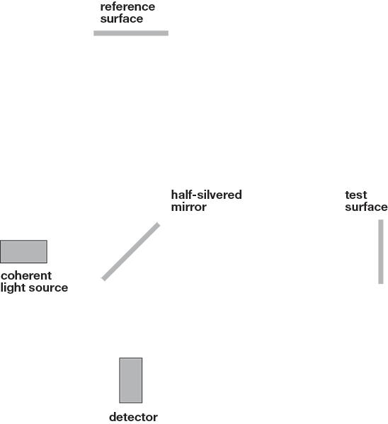
In our static example to the left: the beam leaves the light source, hits the beam splitter which creates two equal beams. Each of these beams travels a different route, called a path, and they are recombined before arriving at a detector. The path difference, the difference in the distance traveled by each beam, creates a phase difference between them. It is this introduced phase difference that creates the interference pattern between the initially identical waves.
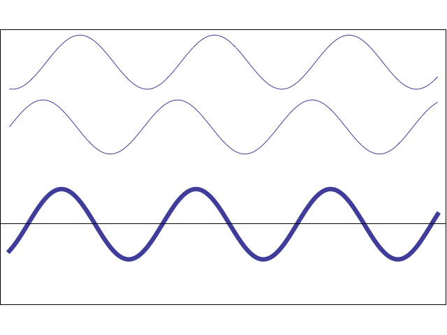
In the example above, the system is static, neither path length is changing. The image below gives a better example of what is happening in the profilometer. The top wave represents the reference path to the detector. Since its path length does not change, the phase of the light in that path does not change. The middle wave represents the test path to the detector. The scanner is moving through Z, changing the path length, which changes the phase of the arriving light at the detector. The resultant wave (bold bottom) shows the intensity of the measured light at the detector.