Well Drilling Operations
Once the well pad has been constructed it's time mobilize the drilling rig and assemble it on the well pad to allow well drilling operations to begin. Most energy companies do not own or maintain their own drilling rigs and therefore they lease rigs from a drilling service company. In fact, energy companies generally outsource the majority of the specialty services they need to develop oil and gas, everything from the seismic work, well site development, drilling, and fracturing, but they do provide technical direction, project management and the money to fund the operation. For shale well drilling specialized drilling rigs are required to handle long and heavy drill strings in order to drill thousands of feet into the ground vertically and then thousands more feet horizontally. These rigs may cost $50,000/day or more to lease, along with the costs of drilling the well with a crew and materials such as casing and cement. A typical well in the Marcellus shale may cost $3-5 million to drill and construct, along with another $3-5 million to hydraulically fracture, so a well may cost between $6-10 million dollars to develop before any oil or gas can be produced, on top of all the upfront exploration, leasing, and well pad construction work.
The drilling rigs used in shale development are usually "top-drive" rigs that are capable of "walking" short distances (on the order of 20 feet) in order to drill multiple wells on one well pad without the need to dis-assemble and re-assemble the rig between each well. Drilling rigs have a lot of moving parts and it can be confusing to know what everything does, especially when drillers use funny-sounding names like monkeyboard and doghouse to describe some of the major components. Below is a graphic with the major components of a drilling rig labeled.
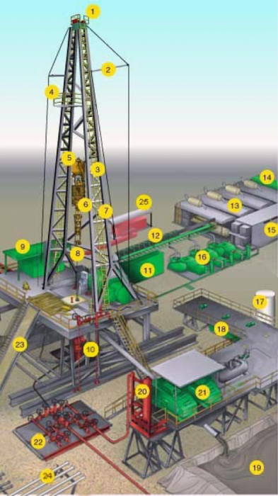
- Crown Block and Water Table
- Catline Boom and Hoist Line
- Drilling Line
- Monkeyboard
- Traveling Block
- Top Drive
- Mast
- Drill Pipe
- Doghouse
- Blowout Preventer
- Water Tank
- Electric Cable Tray
- Engine Generator Sets
- Fuel Tanks
- Electric Control House
- Mud Pump
- Bulk Mud Components Storage
- Mud Pits
- Reserve Pits
- Mud Gas Separator
- Shale Shaker
- Choke Manifold
- Pipe Ramp
- Pipe Racks
- Accumulator
Now we need to develop an understanding of the well drilling process and the safety and environmental protections utilized. A first step in preparing the surface for the drill hole is to install structural casing, commonly known as the cellar, which is typically a 6-10' diameter circular excavation or boring that is lined with a corrugated pipe to stabilize near-surface unconsolidated materials (soil) and to provide sufficient working area for drilling equipment. Drilling requires a drilling bit at the end which is attached to drill string that can be added in segments (typically 30-feet) as the borehole is advanced deeper into the earth as the drilling bit chips and grinds the rock. Drilling bits vary in design, but either a roller-cone bit with three rotating cones or a fixed cutter bit depending on geologic conditions. The steel cones or fixed cutting surfaces are studded with harder tungsten carbide or even diamonds to improve cutting, abrasion, and durability. The drill rig needs to have considerable strength to hold and pull thousands of feet of drill pipe and the drilling bit which is suspended from the rig, this is actually in tension rather than compression.
A drilling fluid is necessary to circulate in the borehole around the drill bit for at least three reasons: 1) to cool the bit and provide lubrication; 2) to lift cuttings (the rock fragments formed during drilling) to the surface (otherwise they would clog the hole); and 3) to counteract the higher gas and fluid pressure in deeper horizons that would cause the well to "blow out." In the shallower part of a hole, drilling must be done with air, fresh water or water-based mud to prevent contamination of the shallow freshwater aquifers. Generally, the salt content (salinity) of fluids trapped in small voids (called pores) in sedimentary strata increases with depth from near-surface drinking-water quality groundwater (less than 500 parts per million dissolved solids), to waters that may have nearly 10 times the salt content of ocean water (ocean water averages about 35,000 parts per million dissolved solids). Deeper in the well, the fluids circulating in the hole must be more and more dense so that their weight will counteract the pressure of gases encountered during drilling that will attempt to rise up the hole. These fluids are actually specially-formulated drilling "mud", a mixture of water, clays, and, commonly a dense mineral called "barite." Drillers monitor subsurface pressure while drilling and constantly adjust the mud density to match the pressure to avoid blowouts and other drilling complications. The driller is in charge of advancing the well into the earth, and sits in the "doghouse" (sounds like they may be in trouble, but they're not!) which is a control room that monitors downhole conditions, drilling depth, drilling direction, weight-on-bit, mud weight, and other data with a clear view of operations on the rig floor.
The process of actually drilling a well begins with drilling in and setting the "conductor casing" which is the largest diameter casing (typically 20-24" in diameter) in the wellbore. Casing must meet American Petroleum Institute (API) strength standards and is fabricated from strong, low-carbon steel. The conductor casing helps to maintain borehole stability in soils and weathered bedrock. The conductor casing provides a connection for the installation of the casing head and blowout prevention stack. A "blowout preventer" will be installed on the conductor casing to prevent any higher pressure zones encountered during deeper drilling from causing a loss of well control incident, otherwise known as a blowout. Subsequent strings of casing (surface, intermediate, and production casing) have decreasing diameters and are hung inside the conductor casing to isolate water from producing formations and to control well pressures during drilling and production. The size of the drilling bits used to drill vertical sections of borehole decrease with depth as does the associated casing diameter installed within in each size borehole, some would describe it as telescoping. Surface casing is set to isolate fresh groundwater from the deeper portion of the well, and prevent lost circulation (drilling fluids flowing into low-pressure, porous formations). The intermediate casing provides protection from deeper low-pressure, gas, oil or brine-bearing zones if they are encountered before the target horizon. Production casing is the last string installed and is set from the surface to the end of the horizontal part of the hole (5.5-inch diameter). This figure provides a cross-section of a typical horizontal well, showing typical casing sizes and depths along the with the purpose of each casing string.
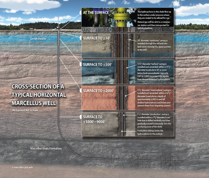
- At the Surface: The hydrocarbons in the shale flow up to the surface under pressure where they are routed to be refined for use.
- Natural gas will be sent to a compressor station and then transported for use via pipelines
- Surface to ± 50': 20" diameter "conductor" casing is installed through the soil and into bedrock to stabilize the upper portion of the well.
- Surface to ± 500': 13 3/4" diameter "surface" casing is installed and cemented within a 17 1/2" diameter borehole to 50' or more below fresh groundwater (typically 500' to 1,000') to protect the aquifer from brine and hydrocarbons.
- Surface to ± 2,000': 9 5/8" diameter "intermediate" casing is installed and cemented within a 12 3/5" diameter borehole to a depth of approximately 2,000' to seal off shallow hydrocarbons and brines and prevent them from migrating upward.
- Surface to ± 5,000' - 9,000': 5 1/2" diameter "production" casing is installed with a 7 3/8" diameter borehole that is drilled vertically and then gradually turned horizontally into the producing zone of the shale.
- Production tubing carries the hydrocarbons to the surface.
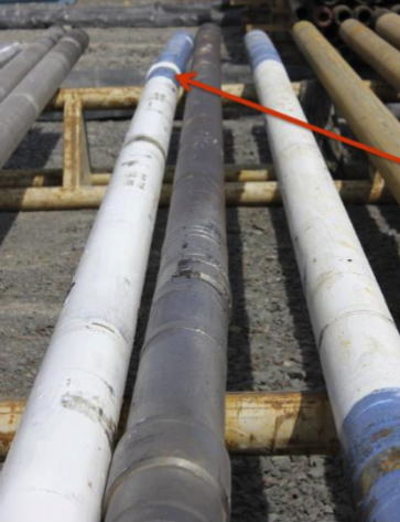
From the "kick-off" point, where the well begins the transition from vertical to horizontal, a different drilling technique is used, with a special drill collar and "mud motor" that can bend at a maximum angle of 3 degrees as shown in the figure below. The angle of the drilling bit/mud motor allows the well to be steered in the direction the drilling bit is pointing. As shown above, in the well cross-section, it takes some vertical distance to actually go from the vertical hole to a horizontal segment, typically about 1,000 feet. The mud motor is driven by a specially-formulated drilling mud pumped at high pressures through the mud motor system causing the bit to rotate. However, the speed of rotation is slower (about 50 rpm) than for the vertical drill bit because of the eccentric nature of the angled system, which would cause excessive wear if rotation rates were greater. Just above the drilling bit/mud motor is the "bottom-hole assembly" which houses a telemetry system with magnetic sensors that can transmit position information to the surface sensors near the drilling bit, including gamma radiation detector, gas sensor, resistivity, and density. Getting this information in real time allows the drilling engineering team to steer the drill bit and well borehole through the most desirable sections of the shale, which is known as "geosteering".
The vertical depth and length of a shale well vary depending on geologic conditions. In the Marcellus shale, the vertical section of a well is commonly 5,000-9,000 feet deep while the horizontal section, also known as the lateral, may be several thousand to upwards of 20,000 feet long! The trend in the Marcellus and other shale plays is for longer laterals to be drilled, which intercepts more shale and therefore can make the well more productive.
This video describes the process of drilling a well, installing casing and cementing each section in place prior to the hydraulic fracturing process.
Video: Well pad preparation and drilling in the Marcellus Shale (8:55)
Narrator: Before drilling begins, we prepare a temporary drill site called a well pad. Our operations are confined to small, controlled sites, in mostly rural areas. We run a very low risk of large-scale damage to the environment. As we create the well pad, you'll start seeing Chesapeake's environmental safety measures at work. A 30-millimeter liner underlines the majority of the well pad. Under the rig itself, there's a rubber composite mat that further protects the surface of the ground, with trenching around mats to collect any fluid migration. Any container or pump on site, holding a potentially harmful material, is stored in secondary containment. Diesel fuel tanks have five redundant levels of containment. A super powerful vacuum that can suck up anything that might need to be contained is also on location. And the well pad itself is surrounded by a 30-inch earthen berm.
Stan Cherry, Chesapeake Energy: The earth berms are designed and constructed around all of our locations here in the Marcellus Shale. They totally surround the location. They are used to direct the runoff, such as rain water or snowmelt, to the sump pump. Which we use that sump pump to redirect that flood to the drilling rig for reuse. If that fluid is not usable, then we dispose of it properly. This level of protection is on every well site that Chesapeake has in the Marcellus Shale.
Narrator: Now that you know a little about what's being done to ensure each Chesapeake well pad and rig are environmentally safe, we'd like to give you an overview of how the drilling process works. There are two ways to drill for natural gas. Vertically, which was how drilling was done for the first hundred years or so, and horizontally, which technological advancements have made possible today. Vertical drilling is just like it sounds, drilling straight down. But in horizontal drilling, the drill bit is actually propelled parallel to the Earth's surface, after reaching a desired depth. Horizontal drilling has become one of the industry's most valuable technologies, because it allows better formation recovery, with the biggest concentrations of clean natural gas, with minimal surface disturbance.
Stan Cherry, Chesapeake Energy: We utilize horizontal drilling to recover the natural gas off of one pad that it would require 36 pads for vertical drilling, that we can do with horizontal drilling. This also reduces the need for multiple access roads and reduces the environmental impact.
Narrator: It's obvious, drilling has evolved significantly since its origin in Titusville Pennsylvania back in 1859, when the placement of a rig was largely hit or miss. Today there's a lot of technology involved that eliminates guesswork, further enhancing the prospects for successful drilling and minimal surface disruption. Chesapeake has its own reservoir Technology Center where we determine whether an area is a viable natural gas production resource or not. For the landowners, that means we know quickly if their land is worth drilling.
Drilling one well lasts about three to four weeks, running 24 hours a day and seven days a week. The process alternates between drilling the hole and installing casing in the drilled hole. Part of the installation process includes cementing each layer of casing into place. Casing provides a strong protective steel pathway for the production tubing that transports the gas. And casing offers layers of separation between the production tubing and the surrounding earth. We repeat the processes of drilling and running casing until the drill bit reaches the depth selected by geologists, known as total depth. The drilling process is controlled by the rig.
Stan Cherry, Chesapeake Energy: We move the drilling rig into the location and we utilize the drilling rig to hoist the drill pipe and drill collars in and out of the hole. The mast and the substructure are designed to handle heavy equipment that allows us to move the drill pipe and drill collars in and out of the hole. Now when we run the drill pipe and collars in the hole we call that tripping in the hole, when we pull the pipe out, then we call that tripping out of the hole. Now when we get through tripping the drill pipe and collars in the hole, we utilize a top drive unit to drive the drill string and it drives many, many thousands of feet of drill pipe and collars while we're drilling.
Narrator: That's the big picture, now some drilling details. Before we even bring the rig on-site, we drill a hole 50 to 80 feet deep. Here we install conductor casing, the first of at least seven layers of protection, ensuring the well is safely and securely isolated from the surrounding earth and shallow drinking water aquifers. The first layer of casing also ensures the wellbore is stable.
Josh Bradford, Chesapeake Energy: Casing provides stability to the wellbore. Our wells contain seven layers of protection. The first three contain steel casing that's run in the hole, there's cement sheathing placed around them. The seventh layer is production tubing which is run in the hole during completion operations.
Narrator: When the rig is on site, surface casing is installed and cemented inside the conductor casing for additional protection. Although it's called surface casing, it actually extends from the ground surface to depths typically between 1,000 and 1,400 feet down. The surface casing and cement completely isolate the well from even the deepest drinking water zones.
Josh Bradford, Chesapeake Energy: Here in the Marcellus, when we drill our holes for surface casing, we drill through a porous rock containing water. Chesapeake uses advanced technology, called air drilling. Air drilling consists of compressors that pump air down the hole to lift rock cuttings and water up out of the wellbore quickly. This minimizes our time drilling in the freshwater zone, guards against shallow formation invasion, and also as extra Environmental Protection.
Narrator: We drill down inside the surface casing to a total depth of up to 8,000 feet. Below the freshwater zone we use conventional drill bits like this. The deeper we go, the smaller the drill bit. Each time we changed the drill bit, we trip out what can be thousands of feet of pipe. After we reach the total planned depth of the well, we install even more steel pipe casing, called production casing. The production casing lines the entire length of the well, inside the other protective layers of casing. It's cemented in place from the very bottom to about 2,500 feet above the production zone, the area producing gas. In some cases, the cement runs all the way to the surface.
Josh Bradford, Chesapeake Energy: In some locations of the Marcellus, there's a fourth string of casing called intermediate casing. Once the cement is placed around it, it is pressure tested for integrity. This brings our total protection to nine layers in our wellbores.
Narrator: As you drill, the heat on the bit is very intense. Drilling fluid or mud is used as lubrication.
Stan Cherry, Chesapeake Energy: The mud consists of non-hazardous magnetic clays and synthetic thickeners. The mud has several functions. It transports rock cuttings to the surface, cools the drill bit, hole stability, and controls downhole pressure. By circulating the mud down the drill pipe, up the wellbore, it will transport rock cuttings to the shakers, where the shaker cleans the mud, disposes of the rock cuttings, and reuses the mud.
Narrator: The mud is further filtered and circulated back down home. The cuttings along with rock cuttings from the air drilling earlier, go in double line steel bins. The cuttings are disposed of according to strict local and state regulations. There's one more important part of a rig that everyone needs to know about because it's yet another kind of protection. It's called the blowout preventer or BOP. A function test is performed on the BOP on a routine basis. This further ensures that the BOP is capable of handling any type of well control incident. In all cases, comprehensive company, federal, and state guidelines regarding proper well control practices are strictly adhered to at all times.
Densiel Bottger, Chesapeake Energy: The blowout preventer is installed right after we run the surface casing. The blowout preventer guards against the uncontrolled release of any gas while drilling. The BOP has valves and seals that line up to the top of the casing. The controls regulate the pressure of the well from the surface and help prevent surface releases. The BOPs are tested every time they're installed.
Narrator: Once drilling is done, it's time for the completion and production processes, when a wellhead is installed and the gas starts flowing, eventually towards your home or business.
All of the casing strings must be centered in the hole (practically and by regulation). This is accomplished by strategically spaced "centralizers" that are attached to the outside of the casing. Casing centralization is critical to the later cement job such that specially formulated cement will ideally fill the "annulus", which is the gap between the formation and the casing, to prevent upward migration of hydrocarbons to the surface or groundwater. Note that poor centralization of casing and cementing was one of the significant factors in the failure of the BP "Macondo Well" in the Gulf of Mexico in 2010.
Cementing is performed on each string of casing. The API recommends different cement formulations, depending on downhole conditions such as temperature, pressure, etc. The cement is mixed and sent down the inside of the casing, followed by a "wiper plug" that pushes the cement downward, through the casing shoe, and up the outside of the casing (the annulus) towards the surface. The volume of cement used is calculated for the depth of the casing string and the average annulus spacing and, by practice and regulation, cement must appear at the surface to provide assurance that the annulus is filled with cement and sealed. The cement, by regulation, must be allowed a minimum of 8 hours to set, during which there can be no other operations in the well that might disturb the casing, and must reach a required minimum compressive strength of 1,200 psi within 72 hours according to Pennsylvania standards.
There are certain downhole logs that can evaluate the efficacy of cement emplacement. These are generally referred to as "cement bond logs" (CBL) and have the capability of sensing if cement has filled the entire annular space between the casing and formation. The CBLs are sonic logs that are run through the casing strings and can be interpreted in terms of the transmission of sound waves through solids. If there are gaps between cement and either the casing or the formation or fluids present in these gaps certain sound waves will not propagate through them and will not be detected by the logging tool. Such logs are not infallible but are critical to evaluating cement jobs that protect against environmental impacts on the environment—either contamination of fresh-water aquifers or direct emissions of greenhouse gases to the atmosphere.
Once the well has been drilled and constructed with steel casing that has been cemented in place, it is time to begin to "complete" the well with the hydraulic fracturing process, which we will explore in the next section.