Hydraulic Head and the Direction of Groundwater Flow
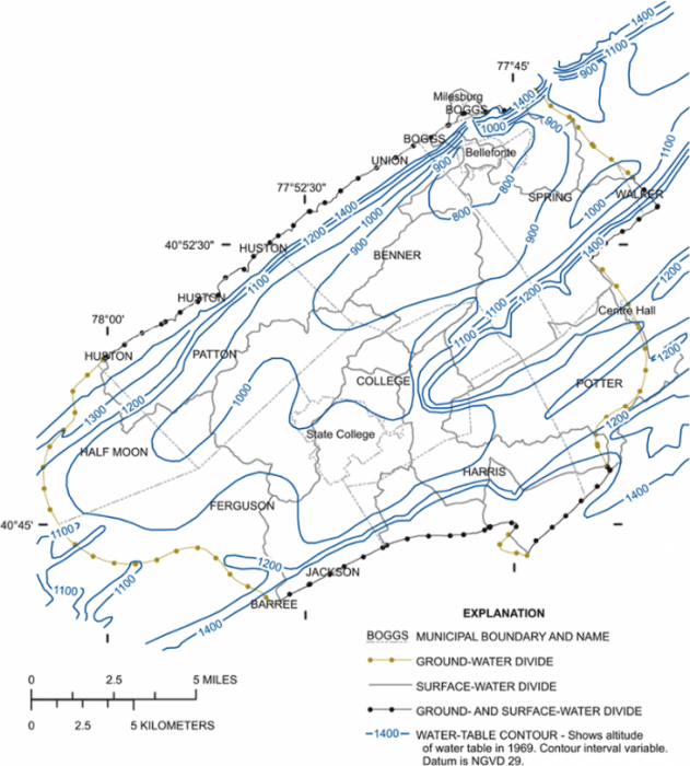
In order to define groundwater flow directions and rates through aquifers, individual measurements of hydraulic head are combined to generate contour maps of water level – or potential energy (Figure 29). These maps define the potentiometric surface, which is much like a topographic contour map but defines the distribution of potential energy in the groundwater system. Each contour, or equipotential, represents a line of equal hydraulic head.
To first approximation, groundwater flows down-gradient (from high to low hydraulic head). As is the case with surface water, or a ball rolling down a hill, the water flows in the direction of the steepest gradient, meaning that it flows perpendicular to equipotentials. There are exceptions to this – for example, if the hydraulic conductivity of the aquifer is much higher in one direction than another, or dominated by fractures with particular orientations, then these can redirect groundwater flow askew to the maximum gradient.
The potentiometric map also provides clues about the rate of groundwater flow. If you think back to Darcy material and our in-class activity from last week, you will recall that groundwater flow rate depends on the head gradient (i.e. the hydraulic gradient) and hydraulic conductivity. In a simple one-dimensional Darcy tube experiment, the head gradient is just the difference (h1-h2)/L. In two dimensions, the head gradient is defined by the slope of the potentiometric surface – just as the slope of the land surface is defined on a topographic map. The path that water takes in the aquifer, defined as a continuous line tracing the maximum gradient on a map of the potentiometric surface, is known as a flowline.