Preliminaries
There are two Inverse Distance Weighting (IDW) tools that you can use to work with this data. The IDW tool can be found in the Spatial Analyst and Geostatistical Analyst tools. While each IDW tool creates essentially the same output, each tool includes different parameters. Both tools include the ability to specify the power, number of points to include when interpolating a given point, whether the search radius is fixed or variable, etc. However, the IDW tool found in the Geostatistical Analyst includes the parameters to change the search window shape (from a circle to an ellipse), change the orientation of the search window, change the length of the semi-major and semi-minor axes of the search window, etc. to enable more of a customizable search window. You can use either tool to complete this lesson. In fact, I would encourage you to experiment a bit with both IDW tools for the first part of this lesson and see what differences result.
To enable the Spatial Analyst:
- Select the menu item Analysis - Toolboxes... and select either the Geostatistical Analyst - Interpolation - IDW or the Spatial Analyst - Interpolation - IDW tool.
Performing inverse distance weighted interpolation
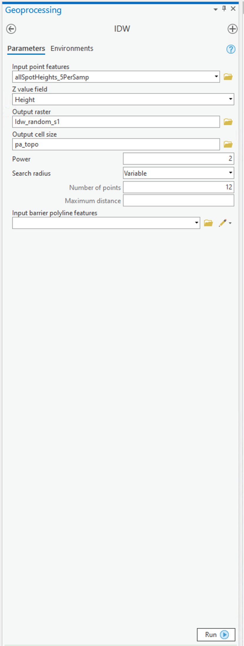
Figure 6.6 shows the IDW dialog for the Spatial Analyst tool.
To set up the Spatial Analyst options:
- Select the Environments... tab item on the tool window - set the Mask to match the allSpotHeights layer. Set the Output Cell Size to be the Same as layer pa_topo.
- Select the Parameters... tab item on the tool window.
- Here are the options on the Parameters tab that you can specify that as discussed in the text:
- Input points specifies the layer containing the randomly sampled control points.
- Z value field specifies which attribute of the control points you are interpolating (in our case, it should be Height).
- Output raster. To begin with, it's worth requesting a <Temporary> output until you get a feel for how things work. Once you are more comfortable with it, you can specify a file name for permanent storage of the output as raster dataset.
- Output cell size. This cell size should be defined as 500 meters already (when you set the Environments... values (see above)).
- Power is the inverse power for the interpolation. 1 is a simple inverse (1 / d), 2 is an inverse square (1 / d2). You can set a value close to 0 (but not 0) if you want to see what simple spatial averaging looks like.
- Search radius type specifies either 'Variable radius' defined by the number of points or 'Fixed radius' defined by a maximum distance.
- Search radius settings here you define Number of points and Maximum distance as required by the Search radius type you are using.
- You can safely ignore the Barrier polyline features settings.
Experiment with these settings until you have a map you are happy with.
Deliverable
Make an interpolated map using the inverse distance weighted method. Insert the map into your write-up, along with your commentary on the advantages and disadvantages of this method and a discussion of why you chose the settings that you did.