Hello! And welcome to Lesson Five in the course. This lesson will be about geodetic reference frames (datums), because it is not possible to use GPS/GNSS without engaging in geodesy.
Therefore, it is necessary to understand the native format of GPS/GNSS coordinates, and how the elements of geodesy influence those coordinates. Geodesy is a complicated subject, but we will be talking about just a few elements of the science.
GPS/GNSS and Geodesy
Today, GPS/GNSS has thrust us into the thick of geodesy, which is no longer the exclusive realm of distant experts. Thankfully, in the age of the microcomputer, the computational drudgery can be handled with software packages. Nevertheless, it is unwise to venture into GPS/GNSS believing that knowledge of the basics of geodesy is, therefore, unnecessary. It is true that GPS/GNSS would be impossible without computers, but blind reliance on the data they generate eventually leads to disaster.
Some Geodetic Coordinate Systems
Three-Dimensional (3-D) Cartesian Coordinates
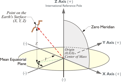
A spatial Cartesian system with three axes lends itself to describing the terrestrial positions derived from space-based geodesy. Using three rectangular coordinates instead of two, one can unambiguously define any position on the Earth, or above it for that matter. The three-dimensional Cartesian coordinates (x,y,z) derived from this system are known as Earth-Centered-Earth-Fixed (ECEF) coordinates. It is a right-handed orthogonal system that rotates with and is attached to the Earth, which is why it is called Earth fixed.
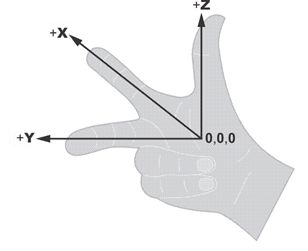
A three-dimensional Cartesian coordinate system is right-handed if it can be described by the following model: the extended forefinger of the right hand symbolizes the positive direction of the x-axis. The middle finger of the same hand extended at right angles to the forefinger symbolizes the positive direction of the y-axis. The extended thumb of the right hand, perpendicular to them both, symbolizes the positive direction of the z-axis.
But such a system is only useful if its origin (0,0,0) and its axes (x,y,z) can be fixed to the planet with certainty, something easier said than done.
This illustration shows the three-dimensional Cartesian coordinate system. It is possible to express a point on the Earth's surface in terms of these x, y, and z-coordinates in this Earth-Centered, Earth-Fixed, or ECEF system. This is the native system in which GPS/GNSS coordinates are expressed; obviously, the plane of the equator, the mean equatorial plane, and the zero meridian (aka Prime Meridian), are vital elements of this system. The usual arrangement is known as the Conventional Terrestrial Reference System (CTRS), and the Conventional Terrestrial System (CTS). The latter name will be used here. The origin is the center of mass of the whole Earth including oceans and atmosphere, the geocenter. Since the satellites orbit around the center of mass of the Earth, it is sensible to have the coordinate system derived from satellites with its origin at the center of mass. It can be used to define a position on the Earth's surface or, for that matter, a position above the Earth's surface. It is possible to have an XYZ coordinate in this system of an orbiting satellite. The x-axis is a line from that geocenter through its intersection at the zero meridian, also known as the International Reference Meridian (IRM), with the internationally defined conventional equator. The y-axis is extended from the geocenter along a line perpendicular from the x-axis in the same mean equatorial plane toward 90° East longitude. That means that the positive end of the y-axis intersects the actual Earth in the Indian Ocean. In any case, they both rotate with the Earth around the z-axis, a line from the geocenter through the internationally defined pole known as the International Reference Pole (IRP).
Polar Motion
The abstract idea of a three-dimensional coordinate system is perfect in the theoretical sense, but when you attach it to the actual, physical Earth, difficulties arise. For example, the Earth's rotational axis just won't hold still. The Earth wobbles so the z-axis of this Earth-Centered, Earth-Fixed three-dimensional Cartesian system is fixed by international agreement.The Earth is constantly moving, of course. While one can say that the Earth has a particular axis of rotation, equator, and zero meridian for an instant, they all change slightly in the next instant. Within all this motion, how do you stabilize the origin and direction of the three axes for the long term? One way is to choose a moment in time and consider them fixed to the Earth as they are at that instant.
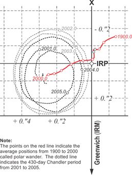
Here is an example of that process of definition. The Earth’s rotational axis wanders slightly with respect to the solid Earth in a very slow oscillation called polar motion. The largest component of the movement relative to the Earth’s crust has a 430-day cycle known as the Chandler period. It was named after American Astronomer Seth C. Chandler, who described it in papers in the Astronomical Journal in 1891. Another aspect of polar motion is sometimes called polar wander. The conventional terrestrial system of coordinates would be useless if its third axis was constantly wobbling. Originally, an average stable position was chosen for the position of the pole. Between 1900 and 1905, the mean position of the Earth’s rotational pole was designated as the Conventional International Origin (CIO) and the z-axis. This was defined by the Bureau International de l’Heure (BIH). It has since been refined by the International Earth Rotation Service, (IERS) using very long baseline interferometry (VLBI) and satellite laser ranging (SLR). It is now placed as it was midnight on New Year’s Eve 1983, or January 1, 1984 (UTC). The moment is known as an epoch and can be written 1984.0. So, we now use the axes illustrated. The name of the z-axis has been changed to the International Reference Pole, IRP epoch 1984, but it remains within 0.005” of the previous definition. It provides a geometrically stable and clear definition of the Earth’s surface for the z-axis.
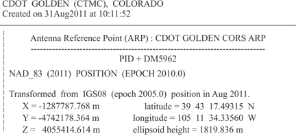
In this three-dimensional right-handed coordinate system, the x-coordinate is a distance from the y-z plane measured parallel to the x-axis. It is always positive from the zero meridian to 90º W longitude and from the zero meridian to 90º E longitude. In the remaining 180º, the X-coordinate is negative. The y-coordinate is a perpendicular distance from the plane of the zero meridian. It is always positive in the Eastern Hemisphere and negative in the Western Hemisphere. The z- coordinate is a perpendicular distance from the plane of the equator. It is always positive in the Northern Hemisphere and negative in the Southern Hemisphere. Here, above, is an example — the position of the station CTMC expressed in three-dimensional Cartesian coordinates of this type expressed in meters, the native unit of the system:
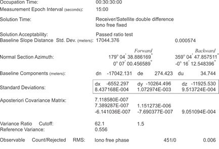
It is important to note that the GPS/GNSS Control Segment generates the position and velocity of the satellites themselves in ECEF coordinates. It follows that most modern GPS/GNSS software provides the GPS/GNSS positions in ECEF, as well. Further, the ends of baselines determined by GPS/GNSS observation are typically given in ECEF coordinates, so that the vectors themselves become the difference between those x, y, and z coordinates. The display of these differences as DX, DY, and DZ is a usual product of these post-processed calculations. This is the way that GPS/GNSS defines vectors. From these coordinates, it is possible to derive any number of other coordinates, i.e., Universal Transfers Mercater System coordinates, State Plane coordinates, latitude, and longitude. All these can be derived from the XYZ coordinates in the three-dimensional Cartesian Earth-Centered, Earth-Fixed system.
Latitude and Longitude
Despite their utility, such 3-D Cartesian coordinates are not the most common method of expressing a geodetic position. Latitude and longitude have been the coordinates of choice for centuries. The designation of these rely on the same two standard lines as 3D Cartesian coordinates: the mean equator and the zero meridian. Unlike them, however, they require some clear representation of the terrestrial surface. In modern practice, latitude and longitude cannot be said to uniquely define a position without a clear definition of the earth itself.
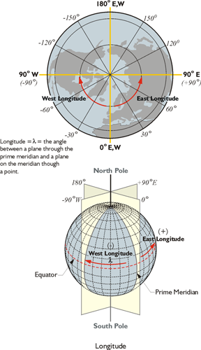
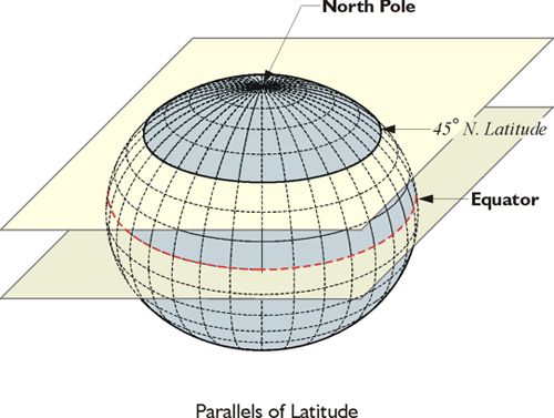
The Prime Meridian is through Greenwich, or approximately through Greenwich. West longitude is negative, is in our neck of the woods. East longitude going the other way around, meeting at the 180 degree longitudinal value. Longitude is usually symbolized by the Greek letter lambda. Latitude is measured from the equator north and south, north being positive and south negative. The plane in the illustration indicates 45 North latitude. There is more than one kind, more than one flavor, of latitude and longitude. In other words, a WGS84 (G1762) latitude and longitude is not the same as a NAD83(2011) latitude and longitude.