Cells layout in a PV Module
PV modules consist of cells, which are sensitive to solar radiation. In order for us to maximize the solar utility of this module when it is installed, we should understand how these cells are wired inside the PV module. Furthermore, it is important to define the factors that contribute to the performance of these cells.
This section will discuss how shading affects the output of solar modules and will also discuss the available solutions to overcome that issue. First of all, let’s start with the wiring of PV cells inside a PV module as shown in Figure 2.3, where the cell connections for a typical commercial 250W panel with 60 cells is illustrated. The PV cells are divided into three groups, and each group of 20 cells has a dedicated bypass diode (illustrated with the triangular shape on top of each group that will be discussed in the next section). When all PV cells are wired in series (the positive of the first cell connects to the negative of the second cell) and then encapsulated within a frame, it forms a PV module with two terminals that are referred to as the positive and negative terminals.
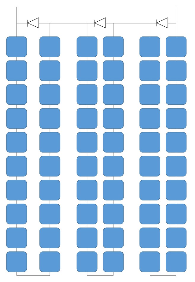
As we expect, all cells are wired in series to get to the desired voltage level of the PV module. However, this series connection raises an issue that when one cell is not generating power due to shading, for example, it will not be able to generate the same amount of current that other similar (unshaded) cells generate. And due to series connection, the total current of the module will be dictated by the weakest cell (shaded). As a result, that will create power loss due to current restriction. In addition, when the higher current generated by unshaded cells tries to pass through the shaded cell, the shaded cell might act like a load and the temperature will increase, and that might lead to a phenomenon known as “hot spot.” Hot spots cause physical damage within the module, like melted cells, cracked glass, or changing characteristics of cells.
Reflection
Why does a shaded cell in series act like an electrical load?
ANSWER: The electrical explanation is that the shaded cell will work on reverse-biased diode mode when connected in series with active cells, that will result in it acting like a load instead of a solar generator.
Bypass Diode
With this said, there should be a solution to protect the modules and cells from the hot spot and also improve the extracted output power when cells are shaded. This can be resolved by adding a “bypass diode” across the shaded cell. In this case, the diode will pass the current and no current will go through the shaded cell. This leads to another important question, how do manufacturers add bypass diodes? Do they add to each cell within the module?
Reflection
How does the bypass diode works, and how dies current pass through it instead of the shaded cell?
ANSWER: When a diode is wired across a cell or group of cells, it is chosen to have the forward biased voltage equal the cell voltage. When the cell is not shaded, it generates voltage that will apply across the bypass diode in reverse biased that will lead to the diode not allowing current to pass through it. When the cell is shaded, its voltage drops across the diode, and that will allow forward biased to apply over the diode. This will lead to the current passing through the diode instead of the shaded cell.
A bypass diode to each cell is not an economical question, and due to the layout of the cells on the panel, the optimal way the bypass diodes are added is as illustrated in Figure 2.4. We can see that the module is divided into groups of cells and each group will have a single bypass diode. In our particular example, we have 3 bypass diodes for the 60 cells module so each 20 series connected cells are protected by one bypass diode.
Is there a difference when cells are shaded with different patterns across the module? Yes - there is a significant impact of the shading pattern, and that is due to the way the bypass diodes are physically connected. Let’s discuss this example: What if only one cell is shaded, as shown in Figure 2.4?
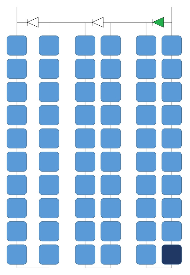
In this case, the string with the shaded cell will not contribute to the total voltage and power of the module; we can estimate that the module might lose 30% of its voltage and power.
Reflection
How does one partly shaded row that shades an equal number of cells from each group affect the voltage of the module?
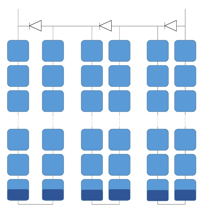
ANSWER: In this case, the module will not lose voltage since the groups are equal in voltage and none of the bypass diodes will be activated. However, the current flowing through each group will be limited to the lowest current of the weakest cell. The shading pattern is shown in Figure 2.5.