The main goal of the PV system is to deliver the energy generated from the sun to the load or the grid, depending on the application. This cannot be achieved without the use of complementary components to allow the current to pass through the circuit. There are multiple electrical BOS components such as conductors, conduits, combiner boxes, protection devices, disconnects, grounding conductors, monitoring devices, and other electrical needed components. These components should be chosen to minimize electrical system losses, and at the same time, to withstand the operating conditions.
In this section, we will focus on the electrical BOS components and their functions as part of the PV system.
In the Electricity Basics section (before we began the course), we learned that conductors are needed to allow current to flow in the circuit. Since we have DC and AC circuits in the PV system and outdoor and indoor installation, we need to consider different properties for each conductor we choose.
Conductors
The conductor insulation should be rated to withstand high temperature and sunlight, since modules are installed outdoors. The main goal is to protect the bare conductor from coming into contact with personnel or equipment.
There are two types of wiring for PV circuits.
1: PV source-circuit wiring
This refers to the wires connecting the PV modules all the way to the combiner box, where stringing of modules are combined. These wires are usually located outdoors and are exposed to UV sunlight, extremely high temperature (90℃ or 194℉), and in some cases, they are exposed to moisture. Examples of insulation types recommended for these installations include USE-2 and PV WIRE.
2: PV output-circuit wiring
This refers to the wires passing through conduits, and they connect the combiner box with the DC disconnect. These cables are still installed outdoors, but they don’t have to be rated to withstand the same extreme conditions that the PV source-circuit wiring experiences. Due to costs associated with PV source-circuit wiring, it is recommended to transition to lower rated wires such as RHW-2, THW-2, THWN-2, and XHHW-2 that still need to withstand the same high temperature without having to be sun resistant.
Interior wires:
When wires enter a space or a temperature controlled environment, it is better to transition to NM, NM-B, or UF types. It should be noted that all interior conductors need to be in metal conduits or enclosures and rated to withstand fire.
Battery wires:
These wires are rated to withstand moisture and must be listed for hard-service use. It is also recommended to have them flexible for easier use. USE, RHW, and THW are commonly used types for battery wiring.
Note:
Please refer to your Required Reading: Chapter 10 from the Dunlop text for more details about insulator types, definitions, and their usages.
PV Wires
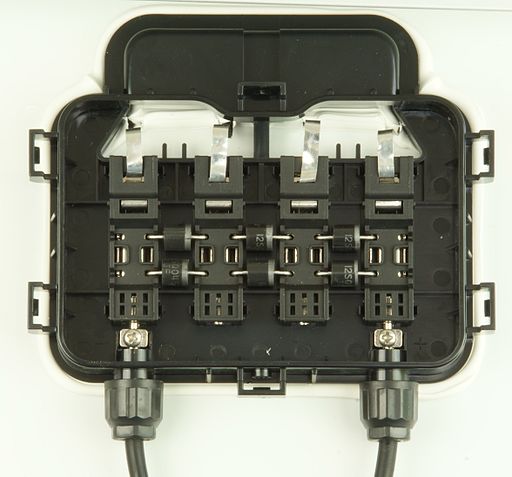
Most modern PV modules come with wires that connect the semiconductor terminals to the outer circuit. This allows current to follow to loads through a protective enclosure, located on the back of the PV module, called the junction box, as illustrated in Figure 5.5. As we can see, the junction box is the interface between the module and the wires. It consists of an outdoor rated plastic box, bypass diodes, and screw terminals for the wires. The junction box is also rated for outdoor operating conditions and must be weather sealed to prevent dust and moisture from building up.
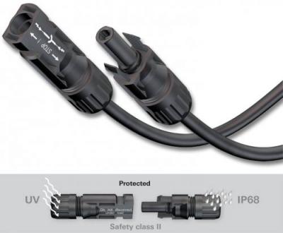
The wires coming out of the junction box are rated for outdoor conditions. Usually, they come with secured terminals, also known as module connectors, such as MC4, as shown in Figure 5.6. We can see that these plugs are weather sealed and also provide safety measures.
Combiner Box
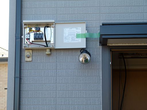
The second main electrical BOS is the combiner box, which combines multiple PV strings into single circuit, as seen in Figure 5.7. Combiner boxes should be rated for outdoor applications and should withstand extreme weather conditions. There are usually screw terminals that apply compression force to secure wire terminals and ensure low resistance at the connection points, inside the combiner box. Lugs can be also used with compression force at the wire terminal. Lugs can have a ring or fork shape to make connections look much cleaner and to make them easier to manage. Protection devices such as Fuses can also be installed inside the combiner box for protection purposes.
Disconnects
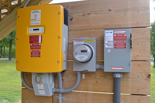
At the entrance and exit of the power conditioning unit, we need to be able to disconnect the current for maintenance work or commissioning procedure. That is usually done using DC disconnect and AC disconnect. In some cases, either or both DC and AC disconnect come as part of the inverter in a built-in device, as shown in Figure 5.8. It can be seen that the inverter has a box attached to the bottom of it with a hand switch that represents the disconnects. In both cases, disconnects need to be rated for the extreme outdoor weather conditions. DC disconnected can also have protection devices such as Fuses or Overcurrent Protection Devices (OCPD). We can also see in Figure 5.8 that the utility requires a separate AC disconnect after the utility meter. This disconnect is a manual lever handle type.
Conduits
Conductors are better protected if they are run through conduits, raceways, and wireways for damage protection and safety precautions. As can be also seen in Figure 5.8, all conductors between the combiner box and the utility disconnects are usually run through conduits.
Conduits can be made of different material types, including:
Metal
- Rigid metal conduit (RMC) is a thick-walled threaded tubing, usually made of coated steel, stainless steel or aluminum.
- Electrical metallic tubing (EMT), sometimes called thin-wall, is commonly used instead of galvanized rigid conduit (GRC), as it is less costly and lighter than GRC.
- Intermediate metal conduit (IMC) is a steel tubing heavier than EMT but lighter than RMC.
Non-Metal
- PVC conduit is the lightest in weight compared to other conduit materials, and usually lower in cost.
- Rigid nonmetallic conduit (RNC) is a non-metallic, unthreaded smooth-walled tubing.
- Electrical nonmetallic tubing (ENT) is a thin-walled, corrugated tubing that is moisture-resistant and flame retardant.
Note:
Other conduits types and their selection and installation are regulated by the National Electrical Code (NEC) and building codes.
Grounding conductors
PV systems need to be grounded to protect people and equipment from electrical hazard and equipment damage. The equipment grounding conductors (EGC) and grounding electrode conductors (GEC) and rods are considered part of the electrical BOS. In special cases, PV systems need to be protected from lightning. That is also done through a special grounding electrode connected to the ground in order to drain the lightning current.
Note:
Your Required Reading: Chapter 11 from the Dunlop text covers the electrical components of the PV system in more detail.