We talked briefly about tracking systems and some design considerations for the tilt angles in Lesson 2. However, we didn’t elaborate on the mounting types available for PV systems. Each PV system is different from the rest in terms of racking structure and mounting types. This is due to the fact that PV systems are space constrained and the installation requirements vary from one place to another. For that reason, many structural holding solutions have been developed to accommodate different needs such as ground mount, pole mount, and roof mount. Each type comes with advantages and disadvantages that allow a good designer to make the optimal decision for each specific PV system.
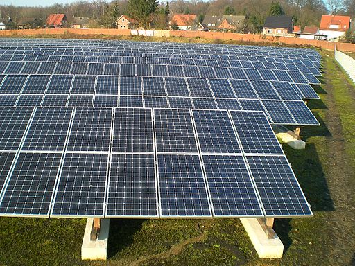
Ground Mount
This type of mounting structure allows multiple rows of modules to be installed on the ground, as shown in Figure 5.1.
Advantages
- Cooler module temperature
- PV modules can get extremely hot during daytime due to the excessive heat generated from the modules and the ambient temperature. The best way to cool down the modules is natural convection using air, which is easily done when modules are elevated from the ground or roof so that air can carry out the heat and cool down the modules.
- Safe installation (no climbing required)
- Easy access for maintenance/troubleshooting
- No roof penetration/liability
- Flexible positioning for max production (potential use for single axis tracking). Ground mount is usually not restricted to be positioned at a certain tilt angle. That said, it is easier to choose the optimum tilt for maximum production.
Disadvantages
- Easy access (theft, vandalism, damage)
- Requires earth construction work (concrete, foundation, trenching)
- Space requirement
- Inter-row shading considerations
- PV modules can shade one another when installed in rows. For example, the first row can shade the second row located behind it. For more information, please refer to the video (6:08) explanation below from EME 810.
Video: Shading Array Demo 1 - EME 810 (6:08)
So here we have the scenario of an array of photovoltaic that are set up one row behind the next. They're each going to have a certain tilt. That tilt is represented by beta and each one is going to have a common collector azimuth of gamma, represented down here. And that gamma again, is that plane or rotation. In this case, the array that you're seeing is rotated 9 degrees towards the east. So minus 9 degrees of rotation or 9 minus 180 degrees to give us our azimuth.
The distance between the panels, right now it's just specified as D. And the panels themselves are going to have a shadow. And that shadow is going to change over the course of the year, as the sun is high in the sky, and low in the sky.
And what we'd really like is for these panels to be spaced appropriately. Such that, they do not block each other. Because this is one of our goals, one of our mechanisms for the goal of solar design. You want to maximize the solar utility for the client or stakeholders in a given locale. And in this locale, want to know how far apart we can space these to collect the energy to basically avoid, or remove shading from the spacing of these panels.
So what you're seeing is a system that we're going to define in terms of critical points. We're going to take those critical points, and we're going to plot them on a diagram. So the first thing is, how do we list these critical points. Well now we don't have a central point X.
Now we actually have three points for each one of the panels across the top and across the bottom. This guy is going to be behind here, you won't see it. But you're going to have three points along the bottom, three points along the top. The points along the top are ultimately going to shade these critical points along the bottom.
So I'm going to name these critical points A, B, and C. And the points that we will be referring to in terms of what kind of shading are we expecting, we're going to label 1, 2, and 3.
So now going into this, you're looking at this from the side, and you're seeing a system like this, there's going to be a certain tilt beta. The beta is going to be the same for both collectors and they're going to be separated by a certain distance D. That's either going to be the spacing from top to top or from bottom to bottom, that's the same spacing with D.
So looking at this, we want to basically compare any point 1. And what we really like to see is, how does 1 compare to point C, point C is down here. One to point C, 1 to point B, and 1 to point A. That's one of our first questions.
And then after we've done that, we're going to look at how this point 2 compares to critical point C, critical point B, and A. And then we'll finally finish that with 3 C, 3 B, and 3 A. And what we should be able to see is that because of similar geometries we're going to find some kind of similar responses, in terms of all of these geometric relationships.
And I can show you that, again this is in the textbook, but if I bring this up right here, you're going to see that I've got a table of points 1.A, 2.A, 3.A, just like what we were talking about. And 1.B, 2.B, 3.B, 1.C, 2.C, 3.C. They each have their own set of altitude angles and you're going to notice that there are certain 21 degree common altitude angles. Just due to common geometries. Similarly, you're going to see common 41 degree angles and two 12 degree angles.
Looking at the azimuth angles, the 0 degree azimuth corresponds to 180 degree in the meteorological standard, and so on down. So we're seeing that 76 degrees is equivalent to 250 degrees. And minus 64 degrees is equivalent to 116 degrees.
So we're going to take these points this 180, 244, 256 for the azimuth angles of the collector. And we're going to plot those in the next block, and we'll plot the alpha angles. And what we're going to come up with is basically something that looks like the cross section of a loaf of bread. It's going to have two vertical sides and it's going to have an arch in the middle.
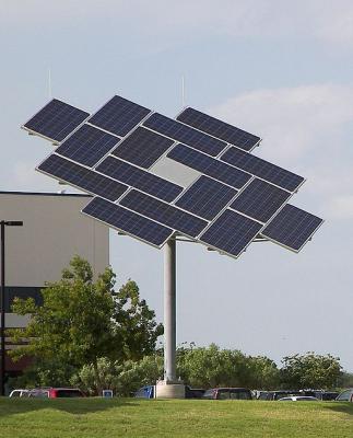
Pole Mount
This structure is common in public areas where the system is space constrained, as seen in Figure 5.2.
Advantages
- Cooler module temperature
- PV modules can get extremely hot during daytime due to the excessive heat generated from the modules and the ambient temperature. The best way to cool down the modules is the natural convection using air, which is easily done when modules are elevated from the ground or roof so that air can carry out the heat and cool down the modules.
- Easy access for maintenance/troubleshooting
- No roof penetration/liability
- Flexible positioning for max production
- Easy to adjust the tilt angle (potential use for dual axis tracking)
- Small footprint (one pole)
Disadvantages
- Easy access (theft, vandalism, damage)
- Requires construction (concrete, steel, foundation, trenching)
Note:
Single and Dual axis tracking systems are discussed in detail in EME 812 (3.3. Types of tracking systems) and EME 812 (3.4. Engineered devices for solar tracking)
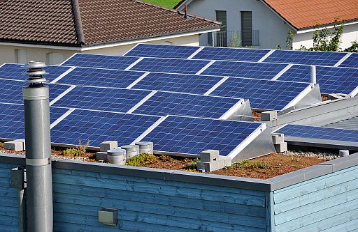
Roof Mount (without roof penetration)
There are various types of roof mounts that don’t require roof penetration especially when the roof is flat, as illustrated in Figure 5.3. Of these types, ballasted roof mount is one of the most used racking structure for PV systems installed on flat roofs. It utilizes the weight of concrete or sand to ensure the system stays still to stand all kinds of external forces such as pullout wind forces.
Advantages
- Low material cost
- Utilizes unused spaces
- Provides secure access for authorized individuals only
- Flexible positioning for ideal production
- No roof penetration needed
Disadvantage
- May require structural engineering and/or roof reinforcement due to added weight
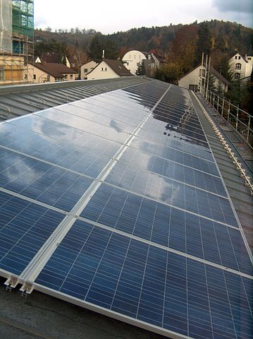
Roof mount (with roof penetration)
These mounting structures allow the system to be installed parallel to the roof for the best esthetic solution for pitched roofs, as seen in Figure 5.4.
Advantages
- Lower material cost
- Utilizes unused spaces
- In most buildings, the roof is considered unused space. PV array can occupy these spaces and transfer them to useful spaces that can generate electricity for the building.
- Provides secure access for authorized individuals only
Disadvantages
- Requires roof penetration (roof leak liability or roof damage)
- Requires professional installers
- Higher module temperature (poor ventilation)
- PV modules can get extremely hot during daytime due to the excessive heat generated from the modules and the ambient temperature. Since PV modules cannot be elevated from the roof for more than a couple of inches, air movement is restricted from carrying out the heat to cool down the modules.
- Difficult conduit runs
- Most roofs have different gable shapes and sizes. In addition, the main electrical panel is usually located at the bottom of the building. That said, the PV array conduits have to run through the roof to the main panel and that route can be wiggly and require more attention to the details when installing the system.
- Fixed title and orientation
- Most roofs come with single pitch that cannot be changed. When a PV array is installed on the roof, the orientation and tilt are restricted by the roof pitch and orientation, and that might affect the production of the PV system.
- Pullout forces
- Wind speed flowing against the PV modules on the roof can cause forces that act similarly to pullout forces that try to remove the modules from the roof. That said, PV designers should ensure that the PV array is securely fastened to the roof using the right attachment mechanisms, such as screws and hooks.
Considerations
- Roof age
- Roof age is a critical factor to installing a PV array. A weak and old roof may not be able to withstand the added weight from the PV array.
- Snow and wind loading
- Snow and wind can add weight to the roof. If the roof is not designed to carry that additional weight, the roof might collapse.
- Fire issues
- When PV arrays are installed on roofs, installers should work with the local fire department to ensure that there are no fire hazards or accessibility issues if fire occurs.
There are other mounting types that are beyond our discussion for this class and students are encouraged to look for different racking structures for their own benefit.
For Further Reading
For more information about the mounting structures of the PV system, please refer to your Required Reading: Chapter 10 from the Dunlop text. Please note that some information in the reading chapter is not directly related to this topic; however, students are encouraged to read through the chapter for their own benefit.