
3.4. Types of tracking systems
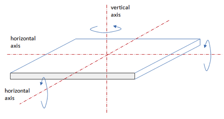
Tracking systems are classified by the mode of their motion. We can define three axes for a moving surface (which represents a receiver): two horizontal axes and one vertical axis (Figure 3.3). The surface can be rotated around each axis (tilted) to achieve an appropriate angle with respect to the incident solar beam. When movement or adjustment of the surface is done by rotating around one axis (tilting), it is single-axis tracking. When rotation of the surface is done around two axes simultaneously, it is two-axis tracking. Two-axis tracking allows for the most precise orientation of the solar device, is reported to provide 40% gain in energy absorption, but it is more complex and costly. Such two-axis systems are also used for controlling astronomical telescopes.
In case of single-axis tracking, the axis of rotation is usually oriented in the N-S direction or E-W direction. Tilting is performed in a way to minimize the incidence angle. In case of two-axis tracking, ideally, the incidence angle is always zero, i.e., the surface is kept perpendicular to the solar beam.
Read about various tracking modes in the following sources.
Reading Assignment
Book chapter: Kalogirou, A, Solar Energy Engineering, Chapter 2: Environmental Characteristics. pp. 64-71. (See E-Reserves via the Library Resources tab.)
This reading is the continuation of the same chapter you read in the previous section of the lesson. It describes different types of single-axis and dual-axis tracking systems and compares their performance by the amount of received solar energy.
Book chapter: Brownson, J.R.S., Solar Energy Conversion Systems, Chapter 7. Applying the Angles to Shadows and Tracking, pp. 192-196. (See E-Reserves via the Library Resources tab.)
This reading gives a few more descriptions of tracking modes, some different from those listed in Kalogirou's book. You will also read here about specific advantages of particular types of tracking systems.
So, from reading these chapters, you now have quite complete list of different ways of tracking, and corresponding formulae to describe the relative position of the sun and inclined surface. The following activities will give you an opportunity to practice the basic calculations involved in two-axis and single-axis tracking. The first problem considers a simple case of two-axis tracking. As long as we know the solar coordinates, we can orient the receiver in that direction. But the tracking system that moves the plane needs precise input data, which we try to obtain here.
Problem 3-2: Dual-axis tracker data
The system is a heliostat with two-axis tracking: one vertical axis, and one horizontal (SN) axis. The goal is to determine the azimuth for the heliostat orientation and tilt angle for the horizontal axis at any time of the day to supply these data to the tracking system. A sketch of the collector is given below, and the blue line is the horizontal axis we want to tilt. The red line denotes the vertical axis, about which the collector can be rotated.
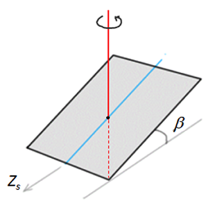
Calculate and tabulate a set of Zs-β data for every hour during the daylight period on March 21 at your chosen location. Feel free to use any available resources (solar path diagrams or appropriate equations) to determine the position of the sun.
In this calculation, we can assume that incidence angle on the surface of the collector will be zero at any moment.
Please provide references and explanation to your work.
This calculation will be submitted as part of Lesson 3 problem set.
The second problem on this topic considers the single-axis tracking case - one with horizontal NS axis and EW tracking (see Kalogirou's chapter, p. 69). In this case, the receiver has only one degree of freedom, so its motion is limited. We will not be able to reach the zero incidence angle, but we will try to minimize it in order to maximize the solar radiation on the plane.
Problem 3-3: Single-axis tracker data
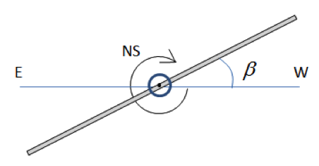
Consider a flat collector with a fixed horizontal NS axis and tilting EW axis (see sketch below, side view). Because the NS axis is fixed, the surface azimuth (Zs) is either -90o when it tilted east, or +90o when it is tilted west. The β angle defines the tilt, which is applied to minimize the incidence angle on the surface.
For your chosen location, determine and tabulate the surface position parameters (Zs-β ) for every hour on March 21st. Feel free to use any available resource to determine the sun position. Make sure to provide references and explanation to your work.
This calculation will be submitted as part of Lesson 3 problem set.