Delayed Coking
Figure 6.6 shows a flow scheme in a delayed coking progress and a photograph of a delayed coking unit. The derricks above the drums that contain the drill stems are used to drill out the coke from the coke drums at the end of the coking cycle.
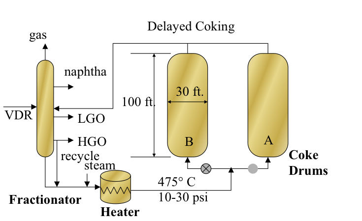
As shown in Figure 6.6, the residue feed is introduced to the fractionator after being heated in the heat exchangers with the coker gas oil products. The bottoms from the fractionator, including the heavy ends of the vacuum residue feed with heavy coker gas oil recycle, are mixed with steam and sent to the tubular heater in the furnace to be heated to approximately 475°C at a pressure of 10-30 psi. Steam is added to prevent coking in the heater, and the heated feed is introduced from the bottom of one of the coke drums. The coking takes place in the insulated coke drum as the drum fills up for a period of 16–18 h. While drum A is being filled up, drum B is decoked by using hydraulic cutters and the drilling stem, and the coke is removed from the bottom of the drum. As the coking in drum A is completed, drum B should be decoked, sealed, heated, and prepared for switching the feed. The coking cycle is controlled such that the vacuum residue is continuously fed to the unit (because the vacuum column works around the clock) and the fluid products are recovered continuously, while coke is removed intermittently in a semi-continuous process scheme. Therefore, there are at least two coke drums in every delayed coking unit, and some units have more than two drums. All of the heat necessary for coking is provided in the heater, whereas coking takes place in the coke drum; hence, the process is called “delayed coking.”
The hot product vapors and steam from the top of the drum are quenched by the incoming feed in the fractionator to prevent coking in the fractionator and to strip the lighter components of the vacuum residue feed. The fractionator separates the coking products into gasses, coker naphtha, coker light gas oil, and coker heavy gas oil. A side-steam stripper is used with the fractionator to ensure a good separation between the coker naphtha and light gas oil streams [2].
The delayed coking operating variables include heater outlet temperature, pressure, recycle ratio, and cycle time. These variables are selected based on feed properties such as the characterization factor, asphaltene content, and Conradson Carbon Residue (CCR) to ensure that coking in tubular heaters is minimized, and liquid product yield is maximized. The recycle ratio, which is typically 3–5%, is used to control the endpoint of the coker heavy gas oil. The coke yield can vary from 20% to 30% depending on the feed properties and coking conditions. In the textbook, you may find some proposed equations to predict coke and other product yields on the basis of the CCR of the vacuum residue and estimates of the distribution of sulfur in the feed among the coking products, suggesting that up to 30 wt% of the sulfur in the feed ends up in the coke, 30 wt% in the gas product, and 20 wt% in the coker heavy gas oil.
[2] Petroleum Refining, by J. H. Gary, G. E. Handwerk, M. J. Kaiser, 5th Edition, CRC Press NY, 2007, Chapter 5, pp.97-111.