Fluid and Flexi-Coking
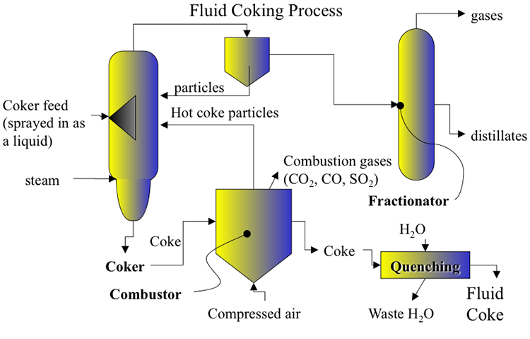
Fluid coking and flexi-coking are fluid-bed processes developed from the basic principles of FCC, with close integration of endothermic (cracking, coking, or gasification) and exothermic (coke burning) reactions. In fluid coking and flexi-coking processes, part of the coke product is burned to provide the heat necessary for coking reactions to convert vacuum residua into gasses, distillate liquids, and coke. Flexi-coking, as a variation of fluid coking, provides the options of partial or complete gasification of the coke product to produce a fuel gas with some or no coke in the product slate. Different from the bulk liquid-phase coking in delayed coking, coking takes place on the surface of circulating coke particles of coke heated by burning the surface layers of accumulated coke in a separate burner. Figure 6.8 shows a schematic flow diagram of the fluid coking process. The preheated vacuum residue is sprayed onto the hot coke particles heated in the burner by partial combustion of coke produced in the previous cycle. Using fluid beds in the reactor and burner provides efficient heat transfer and fast coking on a collectively large surface area of the small coke particles circulating between the reactor and burner. The products of coking are sent to a fractionator (similar to that used in delayed coking after recovery of fine coke particles). Steam is also added at the bottom of the reactor (not shown in the figure) in a scrubber to strip heavy liquids sticking to the surface of coke particles before they are sent to the burner. This steam also provides fluidization of coke particles in the reactor. The reactor and the burner operate at temperatures of 510–570°C and 595–675°C, respectively.
Higher temperatures and short residence times in the reactor lead to higher liquid and lower coke yields compared with those of delayed coking. Coke is deposited layer by layer on the fluidized coke particles in the reactor. Air is injected into the burner to burn 15–30 % of the coke produced in the reactor, part of the particles are returned to the reactor, and the remainder is drawn out as the fluid coke product. Fluid coking can process heavier VDR and gives a higher distillate yield (and lower coke yield) than delayed coking.
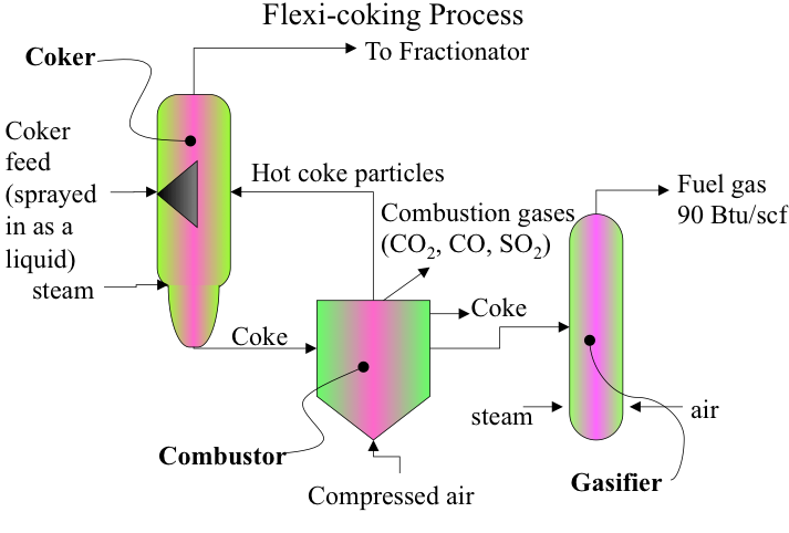
Figure 6.9 shows a schematic diagram of flexi-coking. A gasifier is added for conversion of some or all coke produced in the coker in reaction with air and steam to produce a synthesis gas. The hot coke particles from the combustor are circulated back to the coking reactor to provide the heat necessary for coking. The distillate products from the coker are sent to the fractionator, as is done in the fluid coking process. On the gasifier outlet, after removing the fine particles from the gas by cyclones, the gas is cooled in a direct-contact cooler to condense the sour water and recover the flexi-gas. The product gas can be used as fuel gas in the refinery. Depending on the demand, the flexi-coking process can produce both fluid coke and fuel gas, or gasify all the coke to produce only fuel gas.