Fluid Catalytic Cracking (FCC)
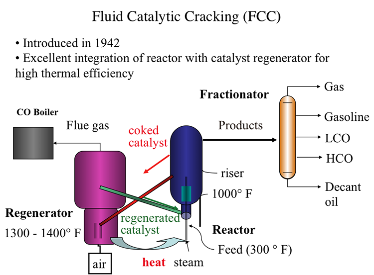
Fluid Catalytic Process, also introduced in 1942, offered an excellent integration of the cracking reactor and the catalyst regenerator that provides the highest thermal efficiency, as shown in Figure 7.7. In FCC, a fluidized-bed (or fluid-bed) of catalyst particles is brought into contact with the gas oil feed along with injected steam at the entrance (called the riser) of the reactor. The hot catalyst particles coming from the regenerator unit evaporate the feed gas oil upon contact in the riser, and the cracking starts as the gas oil vapors and the catalyst particles move upward in the reactor. The temperature of the catalyst particles drops as the evaporation of gas oil and endothermic cracking reactions proceed during the upward movement. Cracking reactions also deposit a significant amount of coke on the catalysts, leading to the deactivation of the catalyst. After removing the adsorbed hydrocarbons by steam stripping, the coked catalyst is sent to the regeneration unit to burn off the coke with air. Heat released from burning the coke deposit increases the temperature of the catalyst particles that are returned to the riser to complete the cycle. Burning off the rejected carbon (coke) in the regenerator provides the energy necessary for cracking without much loss, thus increasing the thermal efficiency of the process. The cracking products are sent to the fractionator for recovery after they are separated from the catalyst particles in the upper section of the reactor [3].
In the reactor, the cracking reactions initiate on the active sites of the catalysts with the formation of carbocations and the subsequent ionic chain reactions produce branched alkanes and aromatic compounds to constitute the crackate (cracked gasoline with high octane number), light olefins, cycle oils, and slurry oil that are sent to the fractionator. A carbon-rich byproduct of catalytic cracking, termed “coke,” deposits on catalyst surfaces and blocks the active sites. FCC is considered a carbon rejection process because the coke deposited on the catalyst surface and eventually burned off for heat is rich in carbon and thus enables the production of large quantities of a light distillate (crackate) in the process without the addition of hydrogen.
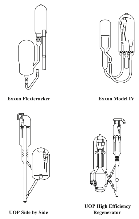
Two different configurations of the commercial FCC processes exist depending on the positions of the reactor and the regenerator: they can be side by side or stacked, where the reactor is mounted on top of the regenerator. Major licensor companies that offer FCC processes with different configurations include Kellogg Brown & Root, CB&I Lummus, ExxonMobil Research and Engineering, Shell Global Solutions International, Stone & Webster Engineering Corporation, Institut Francais du Petrole (IFP), and UOP. Figure 7.8 shows examples of Exxon and UOP designs [1,4]. The UOP design of high-efficiency two-stage regenerator units offer advantages of uniform coke burn, higher conversion of CO to CO2 and lower NOx emissions among others. Another modification to FCC plants could be the installation of a catalyst cooler, which may provide better control of the catalyst/oil ratio; the ability to optimize the FCC operating conditions, increase conversions, and process heavier residual feedstocks; and better catalyst activity and catalyst maintenance [3].
In the first video below, the animation of an explosion in an FCC unit in 2015 (7:12 minute long) provides a good review of the FCC process, and points out the potential hazards of working with hydrocarbons exposed to high temperatures in refinery units:
2015 Explosion at ExxonMobil Refinery (7:12)
SPEAKER: The Torrance refinery is a 750-acre facility located just outside of Los Angeles, California. At the time of the explosion, the refinery was owned by ExxonMobil. An important part of the refining process takes place in the facility's fluid catalytic cracker or FCC unit. In the FCC unit, heavy hydrocarbons from crude oil are broken or cracked into smaller hydrocarbons, which can then be processed into gasoline and other fuel products.
The heavy hydrocarbons are first fed into a reactor where they mix with a catalyst. The heavy liquid hydrocarbons are converted into lighter hydrocarbon vapors as they travel up the reactor. At the top of the reactor, the lighter hydrocarbon vapors are separated from the catalyst. The hydrocarbon vapors then flow to the main distillation column.
The catalyst falls down the side of the reactor, where it moves through a slide valve to a piece of equipment called the regenerator. During the reaction, a layer of carbon called coke forms on the catalyst that must be removed. Inside the regenerator, air is added, and the coke on the catalyst is burned off. The catalyst is then fed back to the reactor through a slide valve, and the cycle is repeated.
When the coke is burned off the catalyst, this creates products of combustion called flue gas. The flue gas flows out the regenerator and enters a system comprised of multiple pieces of equipment which remove any remaining catalyst particles present. The regenerator and flue gas system comprise the air side of the FCC unit.
The last piece of equipment in the flue gas system is called the electrostatic precipitator or ESP. The ESP removes small catalyst particles using static electricity. While the ESP is energized, it creates sparks, which are sources of ignition.
It is critical that the flammable hydrocarbons in the reactor do not flow into the air side of the FCC unit as this could create an explosive atmosphere. To avoid this hazard, the two slide valves connecting the reactor and regenerator are used to maintain a catalyst barrier between the pieces of equipment.
The sequence of events that eventually lead to the explosion at the refinery began on Monday, February 16, 2015, when a piece of equipment in the air side of the FCC unit called the expander vibrated forcefully enough that the refinery's control system automatically transitioned the FCC unit to a standby mode known as safe park.
During safe park mode, the flow of hydrocarbons into the reactor is turned off. The flow of air into the regenerator is also stopped. The two slide valves connecting the reactor and regenerator are closed to ensure a catalyst barrier is maintained. Steam is then forced into the reactor to prevent hydrocarbons in the main distillation column from flowing back inside.
The ESP remains energized during safe park. One slide valve however had eroded over six years of operation. And even though it closed, it could not maintain a catalyst barrier in the reactor. Within seven minutes of the unit going into safe park, all of the catalyst in the reactor fell through the slide valve into the regenerator.
A direct pathway was created for hydrocarbons to flow between the reactor and the regenerator. But the pressure of the steam flowing into the reactor as part of safe park mode was high enough to prevent hydrocarbons in the main column from flowing back inside.
With the unit in safe park mode, operators attempted to restart the expander several times but were unable to do so. Refinery personnel met to identify a strategy to repair the expander and bring the FCC unit back on line. Operations personnel predicted the expander could not restart because catalyst had likely accumulated inside.
On Tuesday, February 17, a meeting took place involving a group of refinery personnel. The group discussed a similar expander outage that occurred in 2012 for which the refinery had developed what is called a variance.
A variance is a management-approved deviation from procedure. The group decided to use the 2012 variance, which allowed a departure from the typical requirements for isolating the expander. Part of that process involved installing a blind in one of the expander's outlet flanges.
On the morning of Wednesday, February 18, Exxon Mobil maintenance attempted to install that blind but were unable to do so because steam was escaping through the open flange. Steam from the reactor had traveled through the leaking slide valve into the air side of the FCC unit.
Using the variance as a guide, the flow of steam into the reactor was decreased in an attempt to reduce the amount escaping from the expander. But the variance did not evaluate whether this flow rate was sufficient to prevent hydrocarbons from flowing into the reactor from the main distillation column.
And unknown to the operators, light hydrocarbons from a separate unit had flowed through a leaking heat exchanger into the main column, increasing pressure inside. With the flow of steam reduced and less pressure in the reactor, nothing could prevent the hydrocarbons from flowing back from the main distillation column. The hydrocarbons flowed into the reactor, where they escaped through the leaking slide valve into the air side of the FCC unit.
At 8:07 AM, a maintenance supervisor working in the FCC unit received an alarm on his personal hydrogen sulfide monitor warning him that hydrocarbons were leaking nearby. By 8:40 AM, multiple workers around the expander received the same alarm, and the FCC was evacuated.
In an attempt to mitigate the problem, a supervisor ordered the flow of steam to the reactor to be increased, but it was too late. A flammable hydrocarbon mixture was flowing through the air side of the FCC unit and moving toward the ESP with its multiple ignition sources. There the flammable hydrocarbon mixture violently exploded.
Video: Fluid Catalytic Cracking (5:08)
Fluid catalytic cracking, or FCC, is the last step in the evolution of cat cracking processes-- also introduced in 1942, just like TCC or Thermafor Cat Cracking, during the Second World War in an effort to make high-octane number gasoline. Remember that high-octane number relates to high power as you can have higher compression ratios in the combustion engines.
FCC really shows an excellent integration of the cracking reactor, an endothermic reactor, with the catalyst regenerator and exothermic reactor for very high thermal efficiency. FCC is now used universally in oil refineries throughout the world-- has replaced all the previous cat cracking processes.
Now, in FCC, in the feed, that is gas oil preheated to about 300 degrees Fahrenheit-- is introduced into the reactor with steam. The riser part of the reactor where the hot catalyst particles-- as you see, the green line coming from the catalyst regenerator-- are full of dyes. The particles are full of dyes because they're smaller particles. They are full of dyes and flowing gases and vapors. So they have a huge surface area to meet the incoming feed at temperatures that are close to 1,000 degrees Fahrenheit.
So cracking reactions on these very fine particles that are full of dyes and flowing with the reactants takes place in a very short space of time, something that could be measured with seconds. And the products are sent to a fractionator after going through a series of cyclones, obviously, to separate the small fluid dyes, the particles of the catalyst.
In the fractionators, the products, as usual, are separated into gas, gasoline, light cycle oil, heavy cycle oil, and, finally, the heaviest fractions, decant oil.
Remember that LCO is used in the US for making diesel fuel through hydrocracking and hydrogenation. And decant oil could be used as fuel oil or as feedstock for making carbon black or white coking to make needle coke for graphites, electrodes.
Coming back to the reactors, the cat cracking reactor, the coked catalyst now, the end of the riser where this cracking reaction takes place, are sent through the regenerator. It's not fully coked on the surface, lost its activity. Through the red line, it's sent to the regenerator where air is introduced to burn off the coke.
The temperatures in the regenerator could reach to 1,300 to 1,400 degrees Fahrenheit. You should remember that the catalysts now are much improved, as well. It may include zeolites that would take high temperatures and very controlled reactivities through pore size distribution and so forth.
So the combustion products or flue gases from this catalyst regenerator could be sent to a CO boiler because the gas may contain significant amount of carbon monoxide, which could be burned to CO2 to provide additional heat or to generate additional heat.
So the catalysts that are now regenerated are sent to the reactor to close the catalyst cycle through that green line, as you see, to meet the incoming feed. So our catalyst cycle is pretty much complete at this point.
But note this excellent integration, thermal integration, of the catalyst regeneration, the exothermic process, with the cracking reactions where the catalysts that are heated in the regenerator are sent in a very effective manner to the reactor without much heat loss. So that is the ultimate, if you will, thermal efficiency of a process. And that's why FCC is now the universally accepted catalytic cracking process.