8.1.1: Construction of the Access
We should talk a little bit about the construction of these means of access. The construction of the drifts, adits, slopes, and ramps does not differ significantly from the unit and auxiliary operations for mining the ore, which we discussed previously. However, these access openings are generally, except to remain serviceable for the life of the mine, unlike many of the other workings that are in use only while the ore in that part of the mine is being exploited. Consequently, extraordinary measures can be justified to ensure the stability of these openings over many years. What are these measures? Reinforced concrete liners, steel arches, and/or additional rock and cable bolts to ensure long-term stability. Some rock types deteriorate when exposed to moisture, and you may shotcrete these surfaces to prevent oxidation and deterioration.
Shaft sinking, on the other hand, may involve some operations and equipment that we didn’t address directly in our study of unit and auxiliary operation. Shaft sinking can be accomplished with a conventional cycle, i.e., drill-blast-muck-hoist, or a continuous cycle using a blind-shaft boring machine. Let’s talk about each cycle.
Previously, we talked about the conventional cycle used in mining as consisting of the unit operations: drill-blast-load-haul. The same unit operations are used to sink a shaft, but the name for loading has changed to mucking and the name for hauling has changed to hoisting. As we sink a shaft into the earth, we cannot load the blasted material with a wheeled loader for example and haul the blasted material off to a dump… obviously! Instead, we use a clamshell mucker to grasp the broken rock and drop it into a large hoist bucket. When the bucket is full, it is hoisted to the top of the shaft and dumped into a waiting truck, where it will be hauled to a dump pile. Hence, the name change for loading to mucking and hauling to hoisting in the conventional cycle for sinking a shaft. It should be noted that the word muck refers to any broken, i.e., blasted, rock, and the word mucking is an old mining term for the operation of loading out muck. Here is a video illustrating the mucking and loading operations in a shaft. This example is for a fairly shallow and small shaft. Larger and deeper shafts involve more complex arrangements, consisting of multiple deck stages and equipment. Nonetheless, this video (2:28) illustrates the basic concept.
During the sinking of the shaft, the auxiliary operation of ground control is generally crucial. The first tens or even a hundred or more feet are driven in relatively poor quality material, e.g., soils and weathered materials that will not stand on their own. In other words, they would tend to fall into the shaft. In areas of past glaciation, the overburden may consist of a hundred feet or more of loosely consolidated rubble. In these areas, the only way to sink a shaft is to freeze the overburden, drill and blast through the frozen material, and then immediately place a liner in the shaft to support the shaft walls. Glaciers made it as far south as Illinois, for example, and so, if you want to sink a shaft down to a coal deposit in the Illinois basin, chances are good that you will have to freeze the alluvial till, i.e., the unconsolidated overburden. Freezing is accomplished by drilling and placing refrigerant pipes around the location of the future shaft, setting up a large refrigeration system, and pumping coolant through the pipes until the ground is frozen. Then, the shaft sinking can begin. Here is a good video (4:37) to illustrate a shaft sinking process in which freezing the overburden is part of the project.
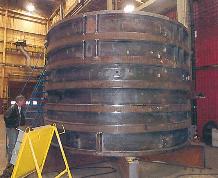
The ground support to maintain the integrity of the shaft walls may consist of rock bolts and wire mesh, but will normally require the use of liners. The liners could be timber, which was used in the past, mortared brick liners, which are also a thing of the past, or most common, concrete liners. In most cases, the concrete liners, a foot or more in thickness, are poured in place. Sometimes, precast liner segments are delivered to the site and set into place, and then a grout is pumped behind the liner to fill the space between the rock wall and the liner. The liners will change over the depth of the shaft depending on the need. If there is a problem with ground water infiltration, steps will be taken to seal the shaft in the water-bearing horizons. This is not as simple as it may seem. At depth, the hydrostatic pressure on that water could reach 500 to 1000 psi or more! To withstand these forces, specially constructed steel liners are used. They may be made out of steel that is ½ to 1” thick, and then welded into place with a concrete ground pumped behind the liner to fill the void between it and the shaft wall. Here’s a picture of such a liner in the shop prior to delivery.
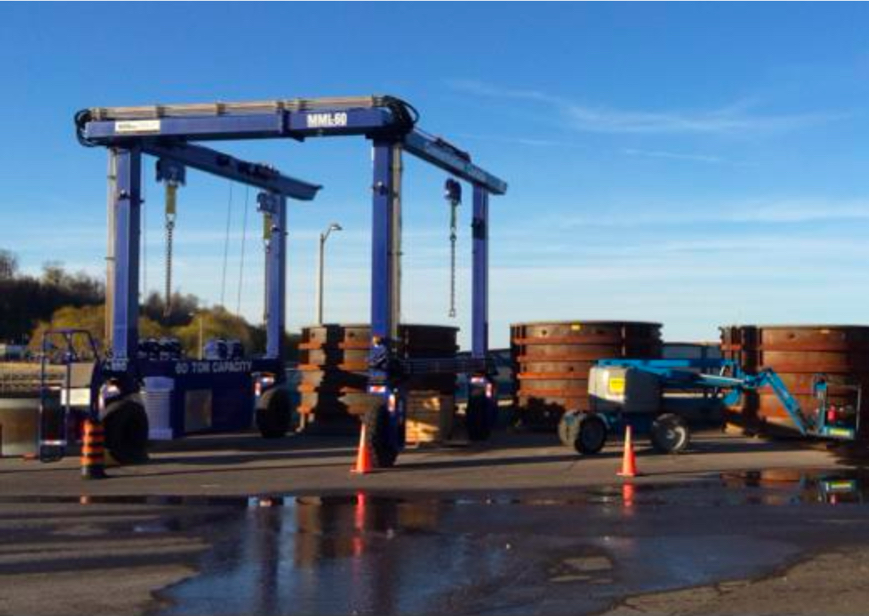
And here is a picture on site. You can see the liners waiting to be installed, along with the gantry for lowering them into the shaft. In this case, they are being set in the first 900’ of the shaft.