8.3.3: Sublevel (Open) Stoping
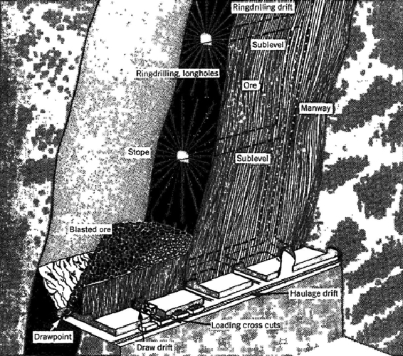
If we had a stronger and more competent host rock, we could dispense with the need to keep ore in the stope to support the hanging wall as we do VCR mining. Indeed, such deposits do exist, and when they do, we can employ the open stoping method. There are different variations, but essentially, we delineate stopes, and then through drilling and blasting, we slice off segments of the ore, and remove the blasted ore through draw points. We often divide the stope vertically by driving sublevels longitudinally, and then we ring drill with the sublevel, charge the holes, and initiate the blast. The progression of the sublevel blasting is coordinated spatially from sublevel to sublevel, so that the blasted ore from a sublevel is free to fall to the bottom of the stope where it will be drawn off.
The vertical spacing between sublevels is limited by the accuracy of the ring drills. As with the innovation of VCR, the accuracy of DTH drilling technology led to a variant of sublevel stoping known as big hole stoping. As you can see in the following figure, the ring drilling has been replaced with long-hole drilling. Using DTH drilling the vertical spacing can be increased significantly, and this means less time and cost to develop the sublevels. The holes are typically on the order of 300’ in length and approximately 6” in diameter. A slice of approximately 10 to 15’ is blasted with each round. Ultimately the size of the blast is limited by concerns of blast damage, and as increasing amounts of explosive are detonated, the risk of damage increases.
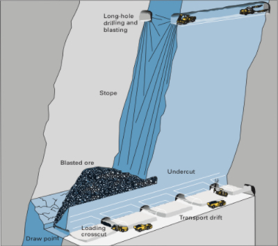
You can also notice in this drawing the vast open spaces created as the stope is mined out. As you recall, a condition for using open stoping is that the host rock be reasonably strong. Here, you can see why this is the case.
In our discussion of shrinkage and open stoping, including the variations of these two major methods, I didn’t say anything about pillars used to separate stopes. There will be a pillar remaining over the entire stope, and this is known as a crown pillar. The pillar underlying the stope is the sill pillar. Finally, there will be pillars separating the stopes transversely, which do not have a special name. Often, there is significant ore of considerable value contained in these pillars. Mining these pillars, however, presents a major challenge: if you attempt to take out the pillar, everything is likely to cave in. It’s rather difficult to recover the ore, if the entire mine in that area has collapsed!
Well, mining engineers are clever, and they have devised means of safely recovering the economic value remaining in the pillars. That’s an interesting story and one that we will tell in the next lesson when we look at cut and fill mining. Stay tuned!
Before moving on to the supported methods, let’s identify some of the equipment commonly found in these different stoping operations.
| Stoping Methods |
|---|
| Jumbo drill |
| Ring drill |
| Down-the-hole drill |
| LHD |
| Mine truck |
| Bolter |
| Powder loader |