8.3.1: Room and Pillar Method
Room and pillar mining is arguably the most important underground mining method in practice today. The majority of underground production comes from room and pillar mines, and the majority of underground mines, by number, employs the room and pillar method! Think about that!
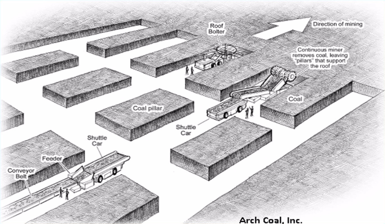
Let’s start out by looking at this sketch of a section in a room and pillar mine. Immediately, you can see that only part of the deposit is mined. Openings are driven in the direction of mining, as shown, and unmined pillars are left in place to support the overlying strata.
Remember from our earlier discussion of ground control: when we mine an opening, the weight of the overlying strata must be supported; otherwise, it will cave. As long as the rock layers over the opening are sufficiently strong (think beam), the weight of the overlying members will be transferred to the points where the beam is supported. Those points are the pillars. And from an engineering perspective, it is essential that you do not make the beam too long, because if you do, the beam will fail in the middle, and you will have a cave-in. Just to make it more interesting, you should know that in addition to choosing an appropriate opening width, which is governed by the allowable span of your beam, you also have to worry about the pillar. In some cases, the pillar is not strong enough to bear the weight being superimposed on it, and it will fail. And, in some cases, the pillar will be sufficiently strong, but the layers comprising the floor will not be, and the pillar will push through the floor. Lots of things to think about! This is one reason why, if you are going to be a mining engineer, you will take a course in rock mechanics and cover ground control design in the underground and surface mining courses.
Anyway, back to our sketch of the room and pillar section. The diagram shown is labeled specifically as a coal mine. In fact, it could just as well be salt, trona, lead, and so on; but with some differences that we will discuss. The active mining areas of coal mines are known as sections. In this diagram, you see one working section. This section consists of the equipment and personnel required to conduct the mining activity. From our earlier discussions of unit and auxiliary operations, you will recognize this as a continuous mining operation; and in the U.S., there are no remaining conventional mining sections in underground coal mines.
The mined-out areas in the sketch are given special names, and these may vary depending on the type of deposit that is being mined. There is one term of special significance: the mined-out areas in the direction of mining are known as rooms. Hence, the name of the mining method, room and pillar. Very clever… Typically, the pillars are laid out in this regular checkerboard pattern in coal mines, and now in most other commodities as well. That was not always the case for the noncoal mines. The size, spacing, and even location of the pillars would vary significantly, as would the dimensions of the openings. In those mines, the method was known as stope and pillar. Although you will still hear the term being used, the distinction has largely disappeared, and the term room and pillar is normally applied across all deposit types employing this general method. As a point of interest here, I would mention that mining engineers now recognize that there are serious shortcomings to the somewhat random placement of pillars, resulting in unnecessary ground failures, e.g., cave-ins. As a result of the art and science developed in underground coal mines, ground control approaches such as the pressure arch approach are more generally applied in all commodities, and this results in a more uniform placement of pillars. You will learn more about this if you take a rock mechanics course.
I want to talk about a few more terms. We’ve defined rooms and pillars. The openings driven between rooms are known as crosscuts. Here, they are shown at an angle of 90 degrees, and that is common; but if you are using continuous haulage, such as the flexible conveyor trains that we covered earlier, then you’ll be driving the crosscuts at a different angle of say 60 degrees. Recall also, that the point at which the material is being freed from the deposit is known as the face. In the sketch, you can see five faces. The continuous miner is mining at one face, and a roof bolter is bolting at another face. Alright, there are just a few more terms, and then we fill in some additional detail for the method itself. Let’s look at this plan view of a room and pillar section.
The sequence of rooms in the direction of mining is known as an entry in a coal mine. They take on the appearance of well-laid-out streets in a city. Indeed, you can stand in an entry and see for quite a distance. If you are in a noncoal mine, you may refer to entries as well, but more likely you’ll call them drifts or headings. What about the sequence of crosscuts? What special name do we assign to that? We don’t assign a special name, and the primary reason is that they do not form a continuous path in the way that rooms do for entries. The reason for that will become clearer within this lesson.
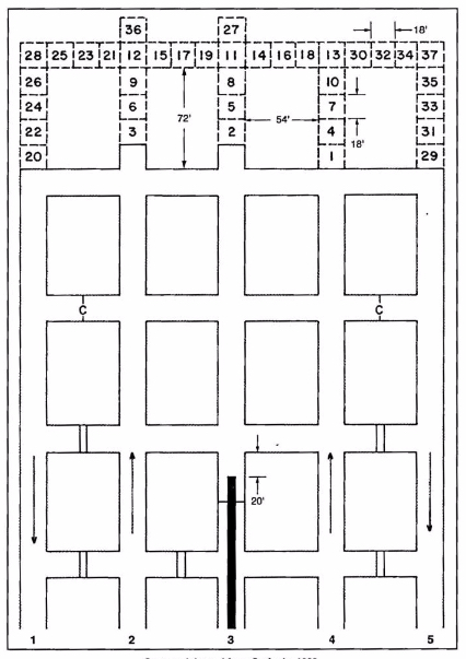
The collection of rooms and pillars shown in this figure form a panel. In this case we have a five-entry panel. Depending on the mining plan this panel could be 10,000’ or more in length, but its width will be determined by the width of the pillars and entries. Three-entry panels are common, as are four and five. There are additional details of note on the plan view.
- There are two different symbols, which appear in the cross cuts: the double line is a solid barrier known as a stopping, and often constructed of concrete blocks; and the single line with a “C” is a flexible curtain, known as a check curtain. Both of these are used to route and separate ventilating air. Recall that you need to provide fresh air to the working places, and then you need to exhaust the air that has become fouled with dusts and gasses.
- The directional arrows are illustrating the direction of the ventilation streams, sometimes called air courses. The air moving toward the face is known as the intake, and the stale air that has already passed the working face is known as the return.
- The thick solid line in entry number three is the conveyor belt.
- The numbered blocks are representing a cut sequence, i.e., block 1 is mined and then block 2, and so on. The cutting sequence will vary by mine, so you don’t need to know this cutting sequence. Simply, it is illustrating that there is a pattern to be followed. This pattern will be designed to optimize productivity and safety.
- The dimensions that are shown will vary somewhat by mine and certainly by commodity; and again, you don’t need to remember these specific numbers.
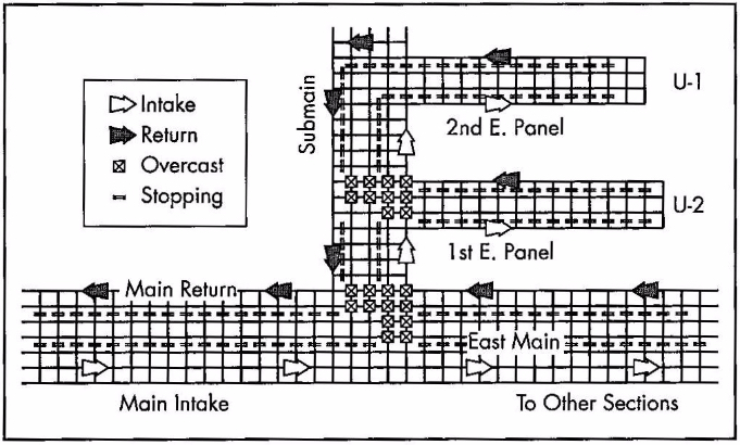
Finally, in terms of this overview, let’s look at this next figure. Notice that we are no longer representing the entries and cross cuts the same way. We’ve replaced them with a single line. That makes it easier and faster to draw these diagrams. As you look at this figure, you will see some of your newly acquired concepts, including Panels, Sections, Intakes, Returns, and Stoppings. There are also three new terms: overcasts, mains, and submains. Overcasts are yet another type of ventilation control joining curtains and stoppings as controls to route ventilating air. Specifically, overcasts are used to route on type of air over tip of another. It’s similar to a pedestrian overpass to allow people to walk over top of a busy highway. The overcast allows us to route, for example, intake air over top of a return aircourse without mixing the two airstreams. To satisfy your own curiosity, go ahead and trace the airflows in the part of the mine represented in the figure.
Now, on to the two other terms that I really wanted to highlight in this figure: the mains and submains. These are common terms in every coal mine and in some industrial mineral mines, e.g., trona. These words are simply designating their importance in the overall mine plan. The mains serve as the primary means of distributing utilities throughout the mine as well as being the location for the primary transportation and materials handling routes. The submains branch off of the mains to provide these same services to a group of panels, and the panels of course are the location for the active production sections. These word, mains and submains, and sometimes panels, are used as adjectives as well as nouns. The major aircourses supply air for the mine are known as the main intakes and main returns, for example. Main haulage of the mine may be a 72” belt, whereas the belts in the submains may be 60”, for example. It is no coincidence that the mains have more entries than the submains, which usually have more entries than the panels. Mains with seven to eleven entries are common. Often, three or four parallel entries are required to serve as intakes in larger mines, with two or three parallel returns, and another two isolated entries for material handling -- one being a belt entry and the other a track (rail) entry.
We now have a basic understanding of the layout for room and pillar mines, and we know the key terms that are used to describe them. We also know either continuous or conventional production cycles can be employed. With this as a solid foundation, let’s complete the picture with the conditions necessary to use a room and pillar method.
This is an underground method for which you can find mines as shallow as 60’ and at depths of greater than 2500’, and so we can conclude that depth is not a particular defining characteristic for the use of this method. The method does require tabular deposits, as opposed to the porphyry or vein deposits; and further, the method requires that the ore be fairly uniform in quality and thickness. Those are defining characteristics. Deposits with little dip (< 15) are necessary, and less dip, the better. There are rare examples of room and pillar being applied to steeply pitching (dipping) coal seams, but they need not concern us at this time. The rock strength needs to be moderate to strong. The rock needs to be strong enough to allow a reasonable span of opening between pillars. The ore strength on the other hand is not quite as important in the choice of the method. As the ore strength declines, it will be necessary to leave larger pillars, and at some point, that becomes uneconomical. In real-world situations, however, the ore strength is rarely an important characteristic for the selection of this method.
Before reading on, please pause for a minute and think about the characteristics that will lead you to select or exclude the room and pillar method from consideration. Specifically, think about the relationship between that characteristic and the design or operation of a room and pillar mine.
I identified the shape of the deposit as important in the selection of this method, and I said that uniform thickness is desirable. In fact, the thickness can vary by 10 or 20%, and not eliminate room and pillar as a viable method. In some cases, the quality of the ore declines rapidly as you approach the interface between the ore and host rock. In those cases, it is not unusual to leave anywhere from several inches to several feet unmined. In still other instances, the competency of the rock in the immediate roof may be very poor, and in those cases, that material will be mined along with the ore. Yes, that will dilute the run-of-mine product, but the additional cost of doing so, may be less than the cost of the ground-control problem that would result from attempting to leave the “bad” roof layer in place.
I did not say anything about the thickness of the orebody. Room and pillar is used successfully in deposits as thin as 24” and as thick as 100’ or more. It is clear that the orebody thickness is not a defining characteristic of the method itself. However, the mining plan and cycle will be affected as the thickness increases. Consider this: you have a continuous miner with a reach of say 15’. Your seam is 25’ thick. How you are going to mine that seam? Are you going to take 15’ out of the 25’, perhaps down the middle, and leave the remainder? Although there might be an instance in which you would do that, generally you would not invest the capital to access the orebody, and then voluntarily leave a lot of it behind! So, back to the question… what are you going to do?
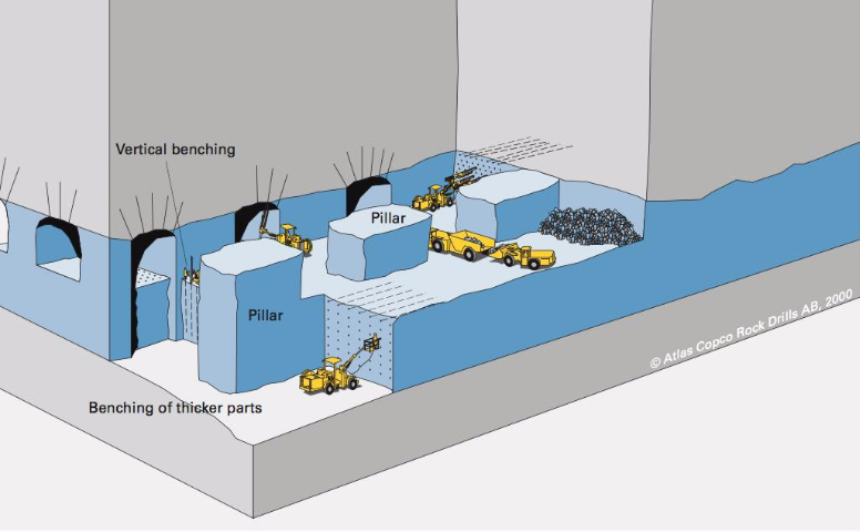
Why not take it out in layers? That is what we do, and we refer to it as benching. We can do this, and it is frequently done with the continuous or conventional cycles. In some instances, both are used, i.e., the top lift or bench is taken with a continuous cycle and the bottom bench is taken with a conventional cycle. In these thicker seams, three of more lifts may be taken. Take a look at this figure.
It is apparent that the first bench is taken at the top of the deposit. This is the norm for room and pillar mining. For one thing, it is easier to scale and bolt the roof form this first bench. This figure is illustrating a conventional cycle, and we can see a couple of interesting practices. Note the drifting or breast stoping occurring on both the top bench and on the lower bench right side. As a contrast, look at what’s happening on the left side and front of the top bench: underhand stoping. They are also showing some overhand stoping, but, to be honest, I have no idea why! If they were moving upwards in the orebody that would make sense… Just ignore that part of the figure! Anyway, this is a good example of benching used in room and pillar mining.
A defining characteristic for the selection of the room and pillar method, as I explained earlier, is a relatively flat lying deposit. What if you meet the characteristics of the unsupported class of methods, except that you have a steeply dipping orebody? You will look more closely at selecting an open stoping or shrinkage stoping method. Next, we will look at these two unsupported methods that are only applicable to steeply dipping deposits that are greater than 50 degrees, and frequently near vertical. The dip angle of the footwall must be greater than the angle of repose for the broken ore because these methods depend on gravity flow to collection points (draw points).