8.3.2: Shrinkage Stoping
Shrinkage stoping is a vertical stoping method, conducted in a vertical or near-vertical plane, and at an angle greater than the angle of repose of the broken ore. A defining characteristic of shrinkage stoping is that most of the blasted (broken) ore remains in the stope to support the hanging wall and footwall. However, when ore is broken, for example by blasting, it swells, i.e., its volume increases. This swell may be as much as 30% or even more. Therefore, as mining progresses within the stope, it is necessary to draw off some of the broken ore – to make room for the next round of drilling and blasting as well as to create space for the next slice of ore to be blasted into. This drawing off was known as shrinking and hence the name associated with this method: shrinkage stoping.
Let’s take a closer look, using the following figure.
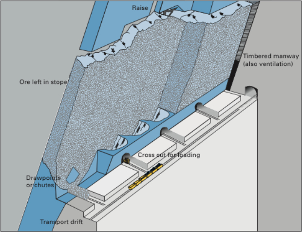
Although not shown, a shaft has been sunk on the footwall side of the deposit, and among other development workings a haulage drift has been driven, and then crosscuts into the orebody. Next, draw points and chutes were constructed by drilling and blasting in exact patterns. Then, the orebody within this stope is undercut. Raises are constructed at each end of the stope to provide manways for personnel access (ladders) as well as to provide ventilation and utilities, such as compressed air lines. This is a very labor-intensive method.
As an overhand stoping method, holes are drilled, loaded, and shot. A portion of the broken ore is drawn off to create sufficient space to allow the drilling and blasting operations in the stope. Once the newly drilled holes are drilled and loaded, the miners and equipment will be withdrawn. At that time, an additional portion of ore will be withdrawn to create sufficient space to account for the swell of the ore that will be blasted. Once this has been done, the round will be fired. Then a portion of the ore will be withdrawn to create space for the overhand stoping to continue. However, before the drillers re-enter the stope, any required ground control will be taken care of. Given that the ores are usually strong, little ground control will be required, other than scaling any loose materials. After it is safe to re-enter the stope, the cycle will repeat.
All right, let’s fill in some additional detail. First of all, why are we leaving ore in place? Essentially to keep the hanging wall and footwall from closing open stope, and causing a failure. Typically, the ore is strong, but the country rock, less so. This method works well with narrow veins, as thin as 3’ or thicker veins of 100’ or so. Stope lengths vary from 150’ to 300’ and heights of 200’ to 300’. In narrow veins, the stopes are laid out longitudinally, whereas in thicker veins they will be transverse. The key design parameters in shrinkage stoping are the dimensions of the stope, largely governed by the size and shape of the deposit. Although rock mechanics will enter the picture in determining size of the stope, the openings used are generally relatively small and are not excessively stressed. Therefore, the major concern is to maintain a manageable-sized stope that ensures a smooth flow of ore by gravity and effective draw control.
A high-quality ore, i.e., high grade and a valuable commodity, is necessary given the high cost of this method. It is labor intensive, and productivity is low compared to other methods. Furthermore, the ore needs to be uniform in quality, as the method doesn’t lend itself well to blending. There are a few other characteristics of the ore that are important. When blasted, the ore should not pack – if it does, you won’t be able to draw it off, and secondary blasting may be required. The ore may remain in the stope for six months to a year, and during that period it should not oxidize, as oxidation can create mineral processing problems, or worse, spontaneous combustion can occur, creating a carbon monoxide and fire hazard.
This method in its original form, as described here is, is unlikely to be used anymore. The last mine that I am aware of in the U.S. was a platinum/palladium mine in Montana. Despite the advantages of this method, it has two really serious disadvantages: one is safety and the other is productivity. Miners working in the stope after each blast presents a level of risk to their safety that cannot be justified by modern standard. From a productivity perspective, there are multiple problems. It requires the use of small equipment and multiple miners. The working surface for the miners is the blasted ore, which makes it difficult to move equipment. Given these serious limitations of the method, you should be asking yourself the question: why are we bothering to talk about this method? As it turns out, there is a modern variation of this method, which is quite successful, and accordingly, quite popular. The variant is known as the vertical crater retreat (VCR) mining method. It was invented by mining engineers working in the nickel mines in Canada. The company, INCO or International Nickel Company as it was known, obtained a patent on the method, and until the patent expired near the end of the 20th century, INCO had exclusive use of this new method.
Vertical Crater Retreat (VCR)
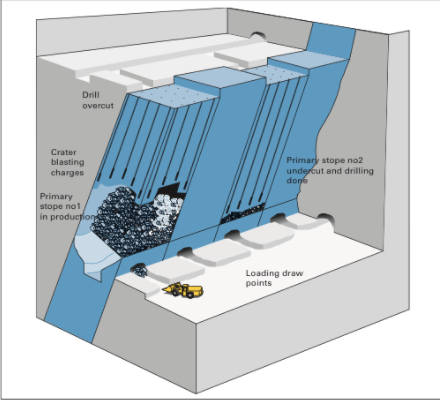
As a variation of shrinkage stoping most of what we said there, applies here, except for the differences that I am going to point out to you now. VCR is much safer because miners and equipment do not enter the stope, and VCR is amenable to a high level of mechanization. In these two differences, VCR has overcome the two primary disadvantages of shrinkage stoping that we identified. This is all well and good, but how does VCR achieve these two improvements? Let’s take a look at the following figure.
Before going into any detail, I should tell the underlying secret that made VCR possible: significant advancements in drilling technology, and specifically down-the-hole drills. You’ll see why this is so important in a moment.
The initial development of the stope for VCR is the same as for a shrinkage stope. The one addition is the need for an overcut at the top of the stope, for that is where all of the drilling and blasting will originate. Either from the shaft or a ramp, crosscuts will be driven over to the overcut level. The overcut will be mined out, and then this will serve as the location where the miners will work. Rather than being in the stope with the attendant hazards, the miners are on top of the stope working from a stable and safe location.
From the overcut, they will use down-the-hole drills to drill the full length for all of the holes that will be required to mine the stope. Drilling holes of that length, accurately, is difficult. If the position of the holes varies by more than a few percent, the rock fragmentation will suffer. Oversize material will result, and will likely cause serious problems when they try to draw down or shrink the stope. Excessive fines will be produced, and they will likely cause plugging and packing. As such, very accurate drilling technology must be used. That’s where the advances in DTH enable the success of VCR. Of course, DTH is only an enabler. It also took clever innovation in the blasting design, and specifically in the development and refinement of crater blasting.
The drilling pattern is a grid on the order of 12’ x 12’. The hole diameters are on the order of 6”. While there is engineering guidance in the literature for the design of these crater blast rounds, many of the best practices are closely guarded secrets within the companies using this method.
Once the holes have been drilled, the lowest part of each drill hole is charged with explosive. The explosive is detonated, and a portion of the fragmented rock is drawn off to make room for the next blast. The lowest part of the holes is again charged, the blast is set off, and the cycle repeats. Usually the blast would be designed to take off a 10’ slice of ore. The design and execution of the spherical charges is technically challenging, and there is significant art as well as science to a successful application of crater blasting.
As with shrinkage stoping, there is some revenue from the ore that is drawn off during the development of the stope, but the real “payday” comes after the stope has been completely fragmented. Then the broken ore can be drawn off and sent to the mill over a period of several months.