Orthophotos
The term orthorectification refers to the process that removes effects of relief displacement, optical distortions from the sensor, and geometric perspective from a photograph or digital image. In a normal photograph, objects closer to the camera appear larger than objects of equal size that are further away from the camera. This presents an obvious difficulty in measuring objects accurately or determining their precise location in a reference coordinate system. In order to use perspective imagery as a map or in a geographic information system (GIS) environment, these geometric distortions must be corrected. The resulting image is referred to as an orthophoto or orthoimage.
Orthoimages can be created from any perspective image, regardless of the source, as long as three things are known:
- interior orientation, which describes the internal geometry of the camera system;
- exterior orientation, which describes the geometric relationship between the image and the ground;
- shape of the ground surface, which must be known in order to remove the effects of relief displacement. A digital terrain model must be supplied as input to the orthorectification process, in addition to the internal and external sensor geometry described above.
Returning to our familiar desktop example, the orthoimage is what would result if we took the 3-dimensional model created by all the intersecting light rays and projected every point straight down from the ground surface to an arbitrary flat plane. Each point would be in its appropriate planimetric (x, y) location, and all the effects of relief would be removed. The resulting image would have the exact same scale everywhere.
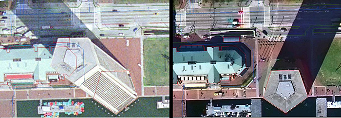
An orthophoto created using an elevation model representing only the bare ground surface will exhibit building lean everywhere except directly below the vantage point of the camera. All USGS and USDA orthophotos are created this way, as are the vast majority of state, county, and municipal orthophotos. On page 188 of Jensen (2007), he shows a comparison of this type of ground orthophoto to a true orthophoto, one which was created using a surface model comprising all of the above ground features at their proper elevation. True orthophotos are preferable in dense urban areas where the lean of tall buildings would obscure many important features on the ground between buildings. Building lean is also very distracting to GIS users, when they overlay building footprint data on top of an orthophoto backdrop. In a true orthophoto, the building footprints will line up with the images of the rooftops; in a ground orthophoto, they will not. Even though both datasets may be equally accurate and correct, the map still doesn't "look right."
Orthophoto Product Specifications
The specification for a digital orthophoto product deliverable must stipulate a ground coordinate system, pixel dimensions, spatial accuracy requirements, and the image file format. These specification elements are usually driven by the end user's application.
Many GIS systems today allow for reprojection of coordinate systems on-the-fly. However, when a raster image such as an orthophoto is projected from one coordinate system to another, it often requires resampling of the pixels, which can degrade the image quality and introduce artifacts. It is also computationally intensive, and can be quite time-consuming if the project includes a large number of high-resolution images. It is usually preferable to have the orthorectification process output orthoimagery in the coordinate system the end user intends to use for analysis. If there are multiple end users with diverse applications, which is often the case, a discussion and agreement on an output coordinate system should be part of the initial project design.
The size of the output pixel must be defined before running the orthorectification process. Knowing the output coordinate system before defining the pixel size is helpful; if one will be working in feet, it is preferable to have pixels defined as a round number interval, such as 1 foot, or 0.5 feet. Likewise for a metric coordinate system, pixel sizes of 1 meter, 50 cm, 30 cm or 25 cm are common. Finally, the GSD of the raw imagery should be considered; there is no point to creating an orthoimage with 25 cm pixels from an input image with a nominal GSD of 1 meter. It is customary to choose an output pixel size slightly larger than the nominal GSD of the input image; for example, if the output pixel size desired is 1 meter, then the project is usually designed for acquisition of data at a nominal GSD of slightly less than 1 meter, such as .8 or .9. This allows for the variation of actual GSD during acquisition due to perspective and relief, as described above, without compromising the spatial resolution of the end product.
Spatial accuracy of the end product depends on the quality of the georeferencing, either as inferred from ground control or provided by direct georeferencing technology. Spatial accuracy and pixel size (GSD) are completely unrelated. The size of a pixel has no physical bearing on the accuracy of its location in the ground coordinate system. However, in practice, it is customary when circumstances permit, to specify a spatial accuracy requirement that is comparable to the size of a pixel in ground units. For example, if the specified pixel size is 1 foot, then the spatial accuracy requirement might be defined such that each 1-foot pixel in the image was assured to be within 1 or 2 feet of its "true" location in the ground coordinate system. This is the ideal. In practice, depending on the end user application, it is not always possible or necessary to follow this rule. If the primary purpose of the imagery is simply to identify objects and measure their size relative to each other, then the absolute spatial accuracy in terms of ground coordinates may be less important. But generally, the rule of thumb is to target a root-mean-square-error (RMSE) for spatial accuracy equivalent to the size of a pixel in the output image. It should be noted, in case it is not already clear, that an orthoimage only has a spatial accuracy component in the horizontal. There is no elevation component to the orthoimage; it is strictly a 2-dimensional product, even though a 3-dimensional terrain model was required in order to produce it.