The Single Vertical Aerial Photograph
The geometry of an aerial photograph is based on the simple, fundamental condition of collinearity. By definition, three or more points that lie on the same line are said to be collinear. In photogrammetry, a single ray of light is the straight line; three fundamental points must always fall on this straight line: the imaged point on the ground, the focal point of the camera lens, and the image of the point on the film or imaging array of a digital camera, as shown in the figure below.
Picture the bundle of countless rays of light that make up a single aerial photograph or digital frame image at the instant of exposure. The length of each ray, from the focal point of the camera to the imaged point on the ground, is determined by the height of the camera lens above the ground and the elevation of that point on the ground. The length of each ray, from the focal point to the photographic image, is fixed by the focal length of the lens.
Now imagine that the camera focal plane is tilted with respect to the ground, due to the roll, pitch, and yaw of the aircraft. This will affect the length of each light ray in the bundle, and it will also affect the location of the image point in the 2-dimensional photograph. If we want to make precise measurements from the photograph and relate these measurements to real world distances, we must know the exact position and angular orientation of the photograph with respect to the ground. Today, we can actually measure position and angular orientation of the camera with respect to the ground with GPS/IMU direct georeferencing technology. But the early pioneers of photogrammetry did not have this advantage. Instead, they developed a mathematical process, based on the collinearity condition, which allowed them to compute the position and orientation of the photograph based on known points on the ground. This geometric relationship between the image and the ground is called exterior orientation. It is comprised of six mathematical elements: the x, y, and z position of the camera focal point and the three angles of rotation: omega (roll), phi (pitch), and kappa (yaw), with respect to the ground. The mathematical process of computing the exterior orientation of elements from known points on the ground is referred to by the photogrammetric term, space resection.
Refer again to the figure above. If we were together in a classroom, I could demonstrate the concept of space resection using my desktop and a photograph taken of my desktop from above. I could use pieces of string to represent individual rays of light; each string is of a fixed length based on the distance from the desktop to the camera when the photo was taken. You'll now have to try to picture this demonstration as I describe it in words. If you feel frustrated, imagine yourself as Laussedat trying to figure this out by himself back in the 1800s.
I attach one end of one piece of string to a particular point on my desktop, I attach the other end of the string to the image of that point on the photograph, and I pull the string taut. With that single piece of string, I cannot precisely locate or fix the position of the camera focal point or the orientation of the camera focal plane as it was when the photograph was taken. Now, I choose a second point, adding a second piece of string, and I pull both strings taut. I can't move the photograph around as much as I could with only one piece of string attached, but the photograph can still be rolled and twisted with respect to the desktop. If I identify yet a third point (that does not lie in a straight line with the first two) and attach a third piece of string, I now have a rigid solution; the geometric relationship between the desktop and the photograph is fixed, and I can locate the focal point of the camera in my desktop model. Adding more points adds to the strength of the geometric solution and minimizes the effects of any small errors I might have made, either cutting the string to its proper length or attaching the strings exactly to the points I identified. When we overdetermine a solution by adding additional, redundant measurements, we can make statistical calculations to quantify the precision of our geometric solution.
We don't have time in this course to go into the mathematics of analytical photogrammetry, but hopefully you can get a sense of it as a true measurement science. In fact, photogrammetry has traditionally been taught as a subdiscipline of civil engineering and surveying, rather than geography. Photogrammetry is not just about making neat and useful maps; a key function of the photogrammetrist, as a geospatial professional, is to make authoritative statements about the spatial precision and accuracy of photogrammetric measurements and mapping products. As you'll see in this lesson and the ones to come, you can easily be trained to push buttons in software to produce neat and interesting remote sensing products for use in GIS. It takes a more rigorous education to make quantitative statements about the spatial accuracy of those products. In my opinion, it is as much the duty of the photogrammetrist or GIS professional to make end users aware of the error contained in a data product as it is to give them the product in the first place. Understanding errors and the potential consequences of error is a very important part of the decision-making process. There's also a particular language used to articulate statements about error and accuracy. You will learn a little of this language in Lesson 6.
The Stereo Pair
Once the exterior orientation of a single vertical aerial photograph is solved, other points identified on the photographic image can be projected as more rays of light, more pieces of string, passing through the focal point of the camera and intersecting the target surface (the ground or my desktop). If the target surface is perfectly flat, then the elevations of the three known points determine a mathematical plane representing the entire surface. It is then possible to precisely locate any other point we can identify in the image on the target surface, merely by projecting a single, straight line. In reality, the target surface is never perfectly flat. We can project the ray of light from the image through the focal plane, but we can't determine the point at which it intersects the target surface unless we know the shape of the surface and the elevation of that point. In the context of our demonstration above, we need to know the exact length of the new piece of string to establish the location of the point of interest on the target surface. This is where the concept of stereoscopic measurement comes into play. If you are interested in learning more about the principles and history of stereoscopy, there is a long but very interesting YouTube video of a seminar with Brian May and Denis Pellerin titled, Stereoscopy: The Dawn of 3-D. Brian May and Denis Pellerin. We've been able to build an entire science of measurement around something that is a natural, built-in, characteristic of the physical human being.
The advantage of stereo photography is that we can extract 3-dimensional information from it. Let's return to the example I described above. This time, imagine I have two photographs of my desktop taken from two separate vantage points, and that the individual images actually overlap. One image is taken from over the left side of my desk, and the other is taken from over the right side of my desk. The middle of my desktop can be seen in both photographs. Now, let's assume that we have established the exterior orientation parameters for each of the two photographs; so, we know exactly where they both were at the moment of exposure, relative to the desktop. We now have two bundles of light rays, some of them intersecting in the middle of my desktop. It is a fundamental postulate of geometry that if two lines intersect, their intersection is exactly one point. Voilà! Now we can precisely locate any point on the desktop surface, regardless of its shape, in 3-dimensional space. For any given point common to both photographs, we now know the exact length of each of the two pieces of string (one from each photograph) that connect to the imaged point on the ground. In photogrammetry, we call this a space intersection. If we have two photographs precisely oriented in space relative to each other, we can always intersect two lines to find the 3-dimensional ground coordinate of any point common to both photographs. The two photographs, oriented relatively to each other, are referred to as a stereo model.
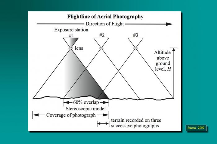
By extension, we could have a large block of aerial photographs, overlapping in the direction of flight as well as between adjacent flight lines, all oriented relatively to each other. This block, once constructed, represents all of the intersecting bundles of light rays from all of the overlapping photos. You can imagine that many of the points will be seen in a number of photographs. In fact, with 60% forward overlap, every point in a single flight line is seen 3 times. If the point falls in the 30% sidelap area between two flight lines, it will be seen 6 times; six rays will all intersect at one point. Actually, because some degree of measurement error is unavoidable, the intersection will occur within some sort of sphere, which represents the uncertainty in the projected coordinate of the point in question. As I mentioned earlier, the mathematical equations of photogrammetry allow us to quantify this uncertainty in statistical terms. Your readings will take you into greater depth and detail, but I hope my explanation helps you create a 3-dimensional picture in your mind, making the readings easier to understand.