In this section, you will learn about the concept of geo-referencing imagery, which is an important concept. Without it, no further photogrammetric processing of the imagery can take place.
In order to utilize the photogrammetric mathematical model, i.e., the collinearity condition, for the production of any mapping products, the following information needs to be made available:
- The exterior orientation parameters for every image: Six parameters which represent the camera attitude or orientation represented by the three rotational angles omega, phi, and kappa, and camera position, which is represented by the three coordinates Easting, Northing, and Elevation at the moment of image exposure.
- The camera interior geometry parameters: The calibrated lens focal length, the principal point coordinates, and the lens distortion as it was discussed in lesson 6.
- The size of the CCD array: The number of pixels contained in the CCD array along the width and the height of the array.
- The physical size of the CCD: Usually provided in microns such as 14 u (1 mm is equal to 1000 um).
- Ground Controls: A ground control is a feature in the imagery with known accurately surveyed coordinates. Depending on the required accuracy of the final products, ground controls can be omitted in some situations.
In this section, we will focus on the process of determining the six exterior orientation parameters. The camera position can be measured accurately using the airborne GPS technique using a GPS antenna on board the UAS. The three camera positions can also be computed using the process of aerial triangulation, as we will discuss soon. However, there are two methods for determining the camera attitude or orientation, and those are the aerial triangulation process and the direct measurement from the IMU, as we discussed in Lesson 6.
Aerial Triangulation and Bundle Block Adjustment
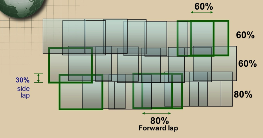
Aerial triangulation is usually performed on a photogrammetric block (Figure 7.2), which consists of all the imagery acquired over the project area. Figure 7.2 illustrates a photogrammetric block of imagery consisting of three strips, each of which has multiple overlapping images. Also shown are the different types of image overlaps. The top and middle strips contain images with 60% forward lap, while the bottom strip contains imagery with 80% forward lap. You may also notice in the figure that the middle and the bottom strips are overlapping by the amount of 30%. Such overlap is called side lap.
In the last section (the photogrammetric process), we mentioned a few terms related to aerial triangulation. We will briefly describe these terms in the following sub-sections:
Relative Orientation
Relative Orientation is the process of orienting images relative to one another (i.e., it recreates the “relative” position and attitude of the images at the instants of exposure), as illustrated below. Figure 7.3 shows four images that are connected to each other in space through the aircraft/GPS trajectory but are not necessarily connected to the ground datum (i.e., they are floating in space).
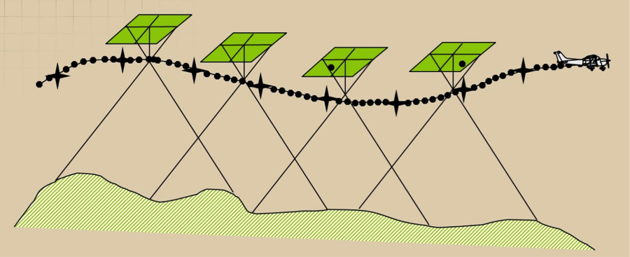
Relative orientation is an important process that must be performed before we scale the imagery to the ground datum through the process of absolute orientation, which will be discussed in the next section. To form a cohesive block, all images in the block should be relatively oriented with respect to each other through the process of relative orientation.
Absolute Orientation
The process of leveling and scaling the stereo model (formed from two images) with respect to a reference plane or datum using ground control points is shown in Figure 7.4. Figure 7.4 represents the same four images as Figure 7.3, but this time the block was tied to the ground datum through the use of seven ground control points (represented by the black stars).
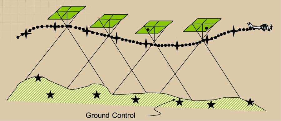
Without performing the absolute orientation process, the generated map would not be specifically associated with a certain location in space. Generating maps that have geo-location information such as datum and coordinates systems can only happen after the process of absolute orientation is performed following relative orientation.
Exterior Orientation
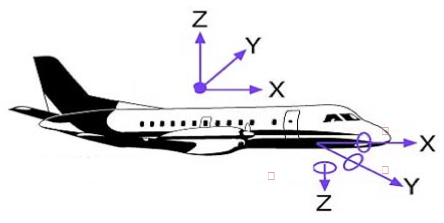
Exterior orientation of a photograph defines its position and orientation in the object space. There are six elements of exterior orientation, X, Y, and Z of the exposure station position, and the three angles that define the angular orientation: ω, φ, and κ. The six elements of exterior orientation are not known and must be computed through a process called space resection within the aerial triangulation process. Here is the definition of the three orientation angles illustrated in Figure 7.5:
-
Omega (ω): Rotation about the x axis. It is equivalent to the angle Roll of the navigation system.
-
Phi (φ): Rotation about the y axis. It is equivalent to the angle Pitch of the navigation system.
-
Kappa (κ): Rotation about the z axis. It is equivalent to the angle Yaw of the navigation system.
Knowing the six exterior orientation parameters for an image is necessary for any photogrammetric processing aimed at creating products from such an image. Whether you perform map compilation on a stereo plotter or generate an ortho image, the six exterior orientation parameters need to be computed before you start the production process.
Space Resection
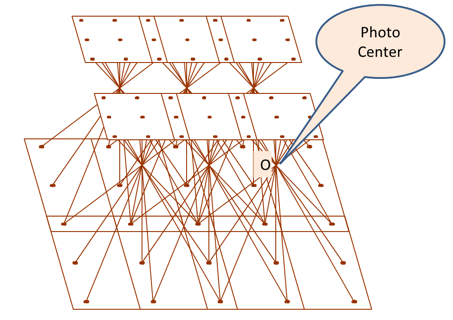
Space Resection is the process of determining ray intersection in space to conclude camera position. See Figure 7.6. The method of space resection is a purely numerical method using collinearity equations to simultaneously yield all six elements of exterior orientation (X, Y, Z , omega, phi, and kappa). Once these elements are known, a stereo plotter can measure the photo coordinates of any point in a photo (x,y) and the ground coordinates can be computed. Ortho rectification software also utilizes space resection for ortho-rectifying an image. Figure 7.6 illustrates six images. Each of them has rays from the ground entering the camera through the lens. The intersection of the rays entering the camera at point "O" represents the photo center location, which is important for the determination of the exterior orientation parameters described earlier.
Aerial triangulation
Aerial triangulation can be defined as the process of densification of a sparsely distributed horizontal and vertical control network through:
- measurements performed on overlapping aerial photographs,
- known ground control points coordinates on the ground, and
- mathematical modeling and solution.
A conventional (film based) aerial triangulation process consists of the following steps:
- preparation
- point marking (for tie points and pass points marking)
- measurement
- computation
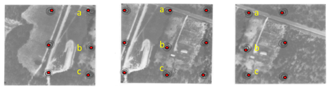
Data Preparation: Using a stereoscope, three points are selected down the center of each photo, approximately 1” from the top and bottom and at the center. These points are also marked on every overlapping photo on which they occur. They are often called “pass points” along strips and “tie points” between strips. See Figure 7.7. Ideally, pass points are selected in flat areas of high contrast that are free of obstructions and shadows.
Figure 7.7 represents three overlapping photos that are used to extract pass points between them. Notice that the three middle points for the middle photo (a, b, c) were located and marked on the same locations in the overlapping right and left image. This process is called point marking.
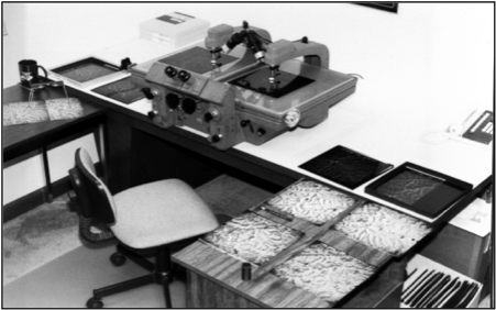
Point Marking: A good point marking device is characterized with:
- precise optics for stereo viewing;
- variable zoom - 6X to 25X;
- laser beams, hot needles, mechanical or electric drills that will remove emulsion from the dispositive;
- the ability to create a very precise circular mark, typically from 40 to 80 microns in diameter.
One of the earliest commercially successful point marking devices was the P.U.G., manufactured by Wild Heerbrugg Instruments, Inc. See Figure 7.8. Over time, pass points marked on dispositive became known simply as pug points.
Point Measurement: A skilled technician with analytical stereo plotting instruments records the location of each previously marked Pass point and tie point on each photograph.
Numerical Computation of Aerial Triangulation: Here is a summary for the steps taken within the processing software:
- Processing numerical observations of individual photographs to build a cohesive block.
- Forming individual photos into strips by successive, relative orientations, using the common primary pass points between overlapping photos.
- Computing Horizontal and vertical coordinates for each strip.
- Converting strip coordinates to ground coordinates using the ground control contained within a given strip.
- Applying simultaneous polynomial equations (horizontal and vertical) to produce final adjusted values for all points.
- Calculating exterior orientation elements for each photo to be used as input to a bundle adjustment program.
Unlike the aerial triangulation of the past, which was performed using film-based imagery instead of digital imagery and optical-mechanical instruments, today aerial triangulation is performed on digital imagery using a complete softcopy approach called softcopy aerial triangulation. In softcopy aerial triangulation, all manual work of points marking and measurements are left to the automation of the software. It is more efficient and more accurate.
Mathematical Model for Aerial Triangulation
The backbone of the computational model in Photogrammetry is based on two equations called the collinearity equations, which are based on the collinearity condition. The two collinearity equations are represented below:
Where,
Xc, Xc, Xc = Camera perspective center
X, Y, Z = ground point position
x, y = point position on image
mii = photo orientation matrix
f = camera lens focal length
x0, y0 = Principal point of autocollimation
Direct Geo-referencing
In the last two decades, navigation technologies have advanced to the point that enabled manufacturers of the Inertial Navigation Systems (INS), usually used for missiles and submarines navigation, to produce an Inertial Measurement Unit (IMU) to accurately measure the orientation of airborne sensors such as cameras and LiDAR. The IMU, which we briefly described in Lessons 2 and 6, are used either to replace the process of aerial triangulation or to assist its solution. Most UAS, including the small ones, carry on board a GPS unit and an IMU unit. Unfortunately, most of these miniaturized low cost IMU that are used for UAS are not accurate enough to replace the aerial triangulation. Such low accuracy IMU is usually used to navigate the UAS but not to support the aerial triangulation. On the other hand, the GPS antenna in most UAS is a survey grade quality that can receive signals from both GPS and GLONASS. Some of the UAS can receive signals from OMNISTAR with real time corrections.
To Read
- Chapter 11 of Elements of Photogrammetry with Applications in GIS, 4th edition
- Section 17-1 to 17-9 of chapter 17 in Elements of Photogrammetry with Applications in GIS, 4th edition