In this section, we will discuss an important topic to any photogrammetric work: ground controls.
A ground control, which we introduced in the last section, is a target in the project area with known coordinates (X,Y,Z). Accurate, well-placed ground controls are essential elements for any photogrammetric project utilizing aerial triangulation.
There are two standard types of ground control points (Figure 7.9), those are:
- Photo Identifiable (Photo ID): This could be any feature on the ground such as a manhole, parking stripe, etc. (the right two images of Figure 7.9). This type of control does not need to be surveyed before the UAS flies the project, as it can be surveyed later on.
- Pre-marked (Panels): This type is generated by marking or painting certain figures or symbols on the ground before the UAS flies the project (the left two images of Figure 7.9). This type of control also does not need to be surveyed before the UAS flies the project as it can be surveyed later on; however, if temporary markers that can be disturbed or moved are used, they should be surveyed ahead of time..
Many projects make use of one type or the other, or a combination of the two.
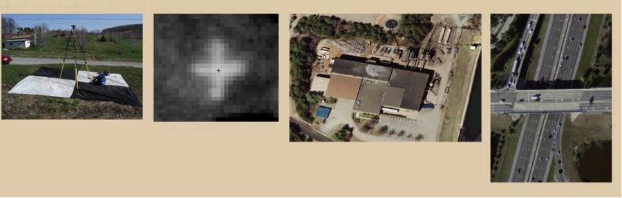
The leftmost image In Figure 7.9 represents a pre-marked control point set on black and white fabric, while the image next to it represent a pre-marked control point that is spray-painted on a sidewalk. The rightmost images represent different types of photo identifiable ground control points. On these images, the user can pick any visible ground feature (such as a parking strip or edge of where the concrete meets the asphalt pavement on a bridge) to use as a control point.
There are two techniques to survey ground control points. The most common one is using RTK GPS techniques, as it is the fastest and least expensive. RTK survey results in a horizontal accuracy of about 2cm and about 3cm vertical accuracy. RTK survey is widely used for mapping projects. The second survey technique which is much more expensive is differential leveling for height determination and static GPS for horizontal survey. Differential leveling results in around 1cm vertical accuracy. Here in the United States, surveying a point using RTK GPS usually costs between $150.0 and $300 depending on the location and terrain. Differential leveling costs around $1,000 to $2,000 per point, again depend on location and terrain. Selecting one type of surveying technique versus another depends on the expected mapping product's accuracy. Consult the American Society of Photogrammetry and Remote Sensing (ASPRS) Positional Accuracy Standards for Digital Geospatial Data and chapter 9 to stand on the accuracy requirement of the ground control based on product accuracy.
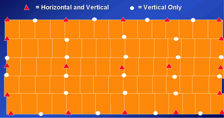
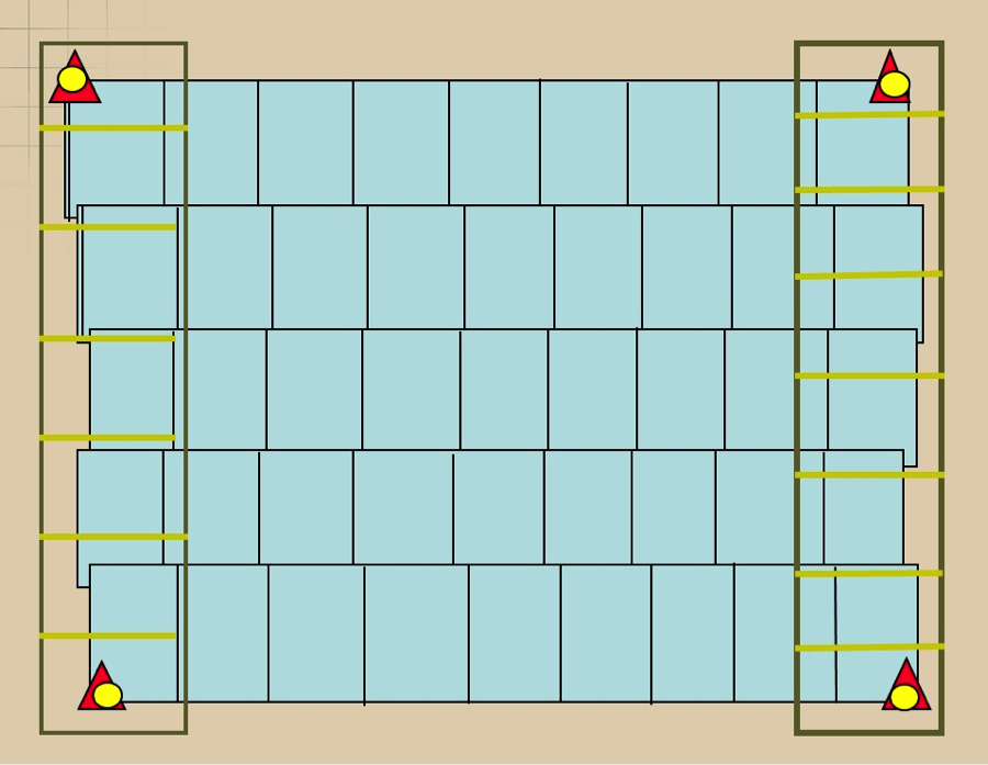
Ground control requirements vary from one project to another depending on the project specifications and its geographic extent. Projects with high geometrical accuracy requirements require more ground controls. Figure 7.10 illustrates typical distribution of ground controls in a rectangular shaped project when the aircraft does not carry on board a GPS antenna, resulting in a non-GPS supported aerial triangulation, or what is usually called “conventional aerial triangulation.”
However, most aerial triangulation today is solved with airborne GPS data. Having GPS data in the aerial triangulation process saves a tremendous number of ground controls. Figure 7.11 illustrates the low density of ground controls required for GPS-based aerial triangulation.
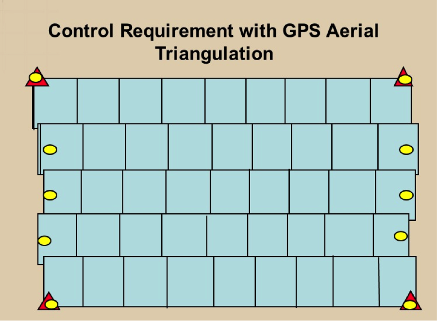
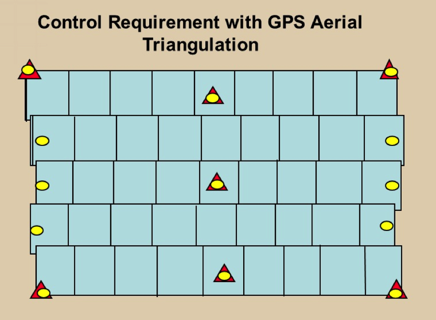
Despite having ground controls only at the edges of the flight line as shown in Figure 7.11, having few additional controls along the interior of the block (see Figure 7.12) is a wise strategy, especially as high accuracy is expected form the aerial triangulation. Savings can be made in the control survey by replacing most of the ground control points at the edges of flight lines with imagery taken with a flight line perpendicular to the project flight lines at each end of the block (see Figure 7.13). Such additional flight lines that are perpendicular to the normal project flight lines are called “cross flight lines.”
Adding two cross flights (strips) at each edge of the photogrammetric block not only saves on number and cost of the ground control points but it also provides strength to the mathematical model within the bundle block adjustment computations. It helps in modeling and solving GPS and IMU problems.
To summarize the subject of ground control requirement for a block, we start with Figure 7.10, which represents the most control consuming case. That is the case of conventional aerial triangulation, where we do not use GPS on the camera during imagery acquisition. Then comes the most efficient method of aerial triangulation, and that is GPS-based aerial triangulation. Figures 7.11 through 7.13 represent different distribution of ground controls for GPS-based aerial triangulation. Each case has its strength and weakness, however, the configuration in Figure 7.13 represents the most economical way when it comes to the reduction in the ground controls requirement.
To Read
- Chapter 16 of Elements of Photogrammetry with Applications in GIS 4th edition