In this section, we will discuss products generated from image-based UAS. Although imagery collected by UAS can be used in a variety of applications in the field of remote sensing, we will focus in this lesson on two main mapping products; those are the ortho photo and the digital elevation model.
Digital Ortho Photo (Ortho Map)
Digital ortho, ortho photo, orthographic image, or ortho map are different names for the same thing. Ortho photo, which I like to call it most of the time, is an image that is corrected (through the process of ortho-rectification) from the effect of terrain relief or sensor tilt to convert it to a unified scale map. Row images taken over variable terrain will have different scales at different locations on the image. Pixels covering the terrain of the ridge of a mountain will cover a smaller spot, as it is closer to the sensor (aircraft), as compared to a pixel covering a valley.
Performing the process of ortho-rectification will sample all these pixels, so each pixel covers exactly the same ground resolution or GSD regardless of where it falls in the image or from which terrain it originated. In other words, ortho-rectification means reprocessing the raw digital image to eliminate the scale variation and image displacement resulting from terrain relief and sensor (camera) tilt.
Because ortho photos are geometrically corrected, they can be used as map layers in GIS, overlaying, management, update, analysis, or display operations. This is a great advantage offered by the ortho photo as compared to the raw imagery.
The five primary ingredients for the ortho photo generation are the following:
- digital imagery;
- digital elevation model or topographic dataset;
- exterior orientation parameters from aerial triangulation or IMU;
- camera calibration report;
- photogrammetric processing software that utilizes collinearity equations.
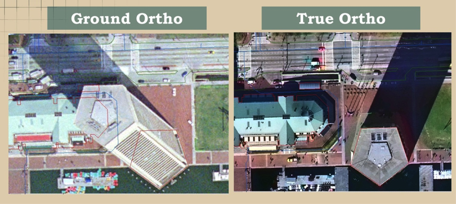
An ortho photo produced using a digital elevation model for the bare earth (no buildings or trees in it) is usually called “ground ortho.” In ground ortho, the building lean is not removed in the process of ortho rectification, and buildings will appear to lean radially away from the center of the image, as you can see in the image of the World Trade Center in Baltimore on the left side of Figure 7.14. On the other hand, "true ortho" is an ortho where the buildings look as if they are erected straight up or as if you are looking at them from right above the roofs, as is illustrated in the right image of Figure 7.14. True ortho is very useful in urban areas, such as downtowns with tall buildings, as it reveals all the information in the streets and pathways surrounding the buildings. True ortho is computationally intensive and needs three-dimensional models of all buildings in the image, which makes it more costly than ground ortho.
It is very important to evaluate the quality of ortho-rectification, as it may cause some defects. Examples of such common defects are the following:
- Image Completeness:
- Root cause: Image not adequately covered by DEM.
- Image Smearing:
- Root cause:
- anomalies or spike error in DEM;
- excessive relief.
- Root cause:
- Double image on adjacent ortho sheets
- Root cause:
- improper camera orientation;
- inaccurate DEMs.
- Root cause:
- Missing Image
- Root cause:
- improper camera orientation;
- inaccurate DEMs.
- Root cause:
- Mismatch of two adjacent orthos
- Root cause:
- inaccurate camera position and orientation;
- inaccurate DEMs.
- Root cause:
Digital Terrain Data
Similar to LiDAR, stereo imagery can be used to generate accurate digital elevation models. Most software used for UAS data processing has the capability of image matching technique to produce fine quality elevation models that can be used for the ortho rectification process and other terrain modeling purposes. The main ingredients for digital terrain data generation are:
- digital imagery;
- exterior orientation parameters from aerial triangulation or IMU;
- camera calibration report;
- photogrammetric processing software that utilizes the image matching technique.
Until recently, users did not trust the poor quality of the auto-correlated digital terrain data. However, in the last couple of years, software development companies adopted a new algorithm called “Semi Global Matching” or SGM that results in fine quality elevation data that in some ways competes with the elevation model generated by LiDAR. This made users excited again about using imagery for the development of a fine quality digital elevation data. The SGM algorithm is a new image matching approach that originated in the computer vision community. It utilizes auto-correlation matching technique based on aggregates per-pixel matching costs that was not possible with the old auto-correlation algorithms.
As it is in ortho photo production, digital elevation data needs to be evaluated to stand on the quality of the data.
There are a couple of terms that are used in the geospatial community to describe digital terrain data, those are:
- Digital Surface Model (DSM): It is also called reflective surface. Such surface represents the original LiDAR data before any feature such as buildings and trees are removed from it. It also represents the elevation model generated from the image auto-correlation process in photogrammetry. Both LiDAR and image auto-correlation collect data on top of natural ground surfaces such as terrain and trees and man-made materials such as buildings and other structures (Figures 7.15 and 7.16 below).
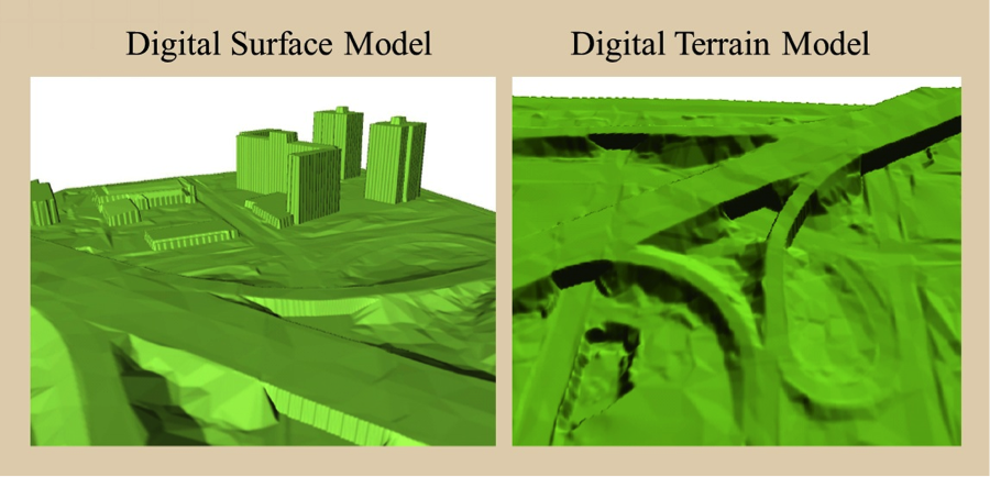
- Digital Terrain Model (DTM): DTM is a term usually associated with digital elevation models of just the ground (trees and man made structures are removed.) DTM is sometimes augmented with 3-D modeling of abrupt changes in the terrain using 3-D lines called break lines. DTM usually contains arbitrary distributed elevation points (not at equal space or grid) called mass points and break lines.
- Digital Elevation Model (DEM): DEM is a term usually associated gridded digital terrain model or points are distributed at equal interval or grid.
-
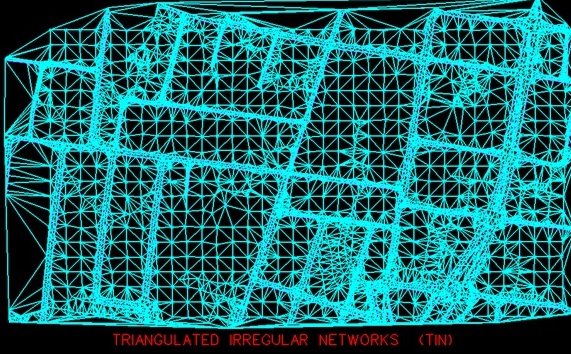
Triangulated Irregular Network (TIN): The term TIN is used to describe the method that most software uses to model the digital terrain data and to present it on the screen. TIN surface represents a set of adjacent, non-overlapping triangles computed from irregularly spaced data points, with x, y horizontal coordinates and z vertical elevations (Figure 7.17).