Understanding CGA Shape Grammar
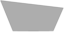
As mentioned, CityEngine uses a programming language called CGA shape grammar. Rules written with CGA are grouped into rule files that can be assigned to initial shapes in CityEngine. For instance, 2D building footprint polygons can be assigned a rule file containing the rules for interactively creating building models from the 2D polygons as illustrated in the figure below. One of the rules defined in the rule file needs to be declared as the starting rule, meaning that the generation of the building model will start with that rule.

The initial shapes to start the iterative refinement process can be created either in CE or imported from another source. More precisely, there are three ways of creating shapes in CityEngine (see image below): (1) manually creating shapes, (2) deriving shapes from a graph (e.g., street segments and lots from road network), (3) importing shapes (e.g., 2D building footprints from a shapefile).
All CGA rules have the format Predecessor --> Successor
Where “Predecessor” always is the symbolic name of the shape that should be replaced by the “Successor” part on the right side of the arrow. The “Successor” part consists of a number of shape operations that determine how the new shape is derived from the input shape and symbolic names for the output shape(s) of the rule (which can then be further refined by providing rules where these shape symbols appear on the left side of the arrow). To give an example, the following two rules create a block separated into 4 floors from a 2D polygon:
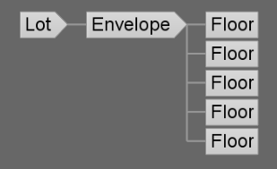
Lot  --> extrude(10) Envelope

Envelope --> split(y) { ~2.5: Floor }*
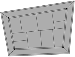
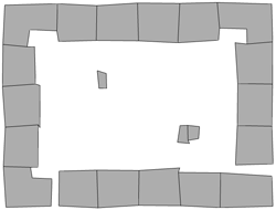
The first rule states that the initial 2D shape (“Lot”) should be replaced by 3D shapes called “Envelope” that are produced by extruding the initial 2D polygon by 10 units. The second rule says that each “Envelope” shape created by the first rule should be split along the vertical y-axis into “Floor” shapes of height 2.5, so four floors altogether. We could extend this simple example by adding rules for splitting each floor into the front, back, and side facades, applying different textures to these, inserting windows and doors, and so on. Application of a rule file to the initial shapes results in a shape tree of shapes created in the process. The leaves of the tree are the shapes that will actually make up the final model, while all inner nodes are intermediate shapes that have been replaced by applying one of the rules. The shape tree for the simple example would start with the “Lot” that is replaced by an “Envelope” shape, which in turn is replaced by the four “Floor” shapes making up the leaves (see figure below).
CGA defines a large number of shape operations (see CGA Shape Grammar Reference). Shape operations can have parameters such as the extrude and split operations in the previous example. Rules can also be parameterized to provide additional flexibility (see Parameterized Rule). Moreover, rules can be conditional (see Conditional Rule or Stochastic Rule), and rule files can contain attribute declarations (see Attributes), function definitions (see Functions), and style definitions (see Styles). If you want to learn more about writing CGA rules, tutorials 6 to 9 at Introduction to the CityEngine Tutorials would be a good starting point.