To understand why topographic maps can't be traced directly off of most vertical aerial photographs, you first need to appreciate the difference between perspective and planimetry. In a perspective view, all light rays reflected from the Earth's surface pass through a single point at the center of the camera lens. A planimetric (plan) view, by contrast, looks as though every position on the ground is being viewed from directly above. Scale varies in perspective views. In plan views, scale is everywhere consistent (if we overlook variations in small-scale maps due to map projections). Topographic maps are said to be planimetrically correct. So are orthoimages. Vertical aerial photographs are not, unless they happen to be taken over flat terrain.
As discussed above, the scale of an aerial photograph is partly a function of flying height. Thus, variations in elevation cause variations in scale on aerial photographs. Specifically, the higher the elevation of an object, the farther the object will be displaced from its actual position away from the principal point of the photograph (the point on the ground surface that is directly below the camera lens). Conversely, the lower the elevation of an object, the more it will be displaced toward the principal point. This effect, called relief displacement, is illustrated below in Figure 6.12.1. Note that the effect increases with distance from the principal point.
At the top of the diagram above, light rays reflected from the surface converge upon a single point at the center of the camera lens. The smaller trapezoid below the lens represents a sheet of photographic film. (The film actually is located behind the lens, but since the geometry of the incident light is symmetrical, we can minimize the height of the diagram by showing a mirror image of the film below the lens.) Notice the four triangular fiducial marks along the edges of the film. The marks point to the principal point of the photograph, which corresponds with the location on the ground directly below the camera lens at the moment of exposure. Scale distortion is zero at the principal point. Other features shown in the photo may be displaced toward or away from the principal point, depending on the elevation of the terrain surface. The larger trapezoid represents the average elevation of the terrain surface within a scene. On the left side of the diagram, a point on the land surface at a higher than average elevation is displaced outwards, away from the principal point and its actual location. On the right side, another location at less than average elevation is displaced towards the principal point. As terrain elevation increases, flying height decreases and photo scale increases. As terrain elevation decreases, flying height increases and photo scale decreases.
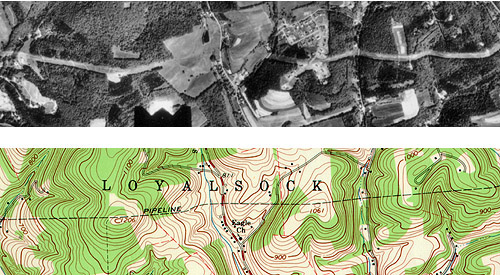
Compare the map and photograph below in Figure 6.12.2. Both show the same gas pipeline, which passes through hilly terrain. Note the deformation of the pipeline route in the photo relative to the shape of the route on the topographic map. The deformation in the photo is caused by relief displacement. The photo would not serve well on its own as a source for topographic mapping.
Still confused? Think of it this way: where the terrain elevation is high, the ground is closer to the aerial camera, and the photo scale is a little larger than where the terrain elevation is lower. Although the altitude of the camera is constant, the effect of the undulating terrain is to zoom in and out. The effect of continuously-varying scale is to distort the geometry of the aerial photo. This effect is called relief displacement.
Distorted perspective views can be transformed into plan views through a process called rectification. In Summer 2001, student Joel Hamilton recounted one very awkward way to rectify aerial photographs:
"Back in the mid 80's I saw a very large map being created from a multitude of aerial photos being fitted together. A problem that arose was that roads did not connect from one photo to the next at the outer edges of the map. No computers were used to create this map. So using a little water to wet the photos on the outside of the map, the photos were stretched to correct for the distortions. Starting from the center of the map the mosaic map was created. A very messy process."
Nowadays, digital aerial photographs can be rectified in an analogous (but much less messy) way, using specialized photogrammetric software that shifts image pixels toward or away from the principal point of each photo in proportion to two variables: the elevation of the point of the Earth's surface at the location that corresponds to each pixel, and each pixel's distance from the principal point of the photo.
Another even simpler way to rectify perspective images is to view pairs of images stereoscopically.