Aerial images need to be transformed from perspective views into plan views before they can be used to trace the features that appear on topographic maps, or to digitize vector features in digital data sets. One way to accomplish the transformation is through stereoscopic viewing.
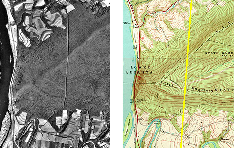
Below in Figure 6.14.1 are portions of a vertical aerial photograph and a topographic map that show the same area, a synclinal ridge called "Little Mountain" on the Susquehanna River in central Pennsylvania. A linear clearing, cut for a power line, appears on both (highlighted in yellow on the map). The clearing appears crooked on the photograph due to relief displacement. Yet we know that an aerial image like this one was used to compile the topographic map. The air photo had to have been rectified to be used as a source for topographic mapping.
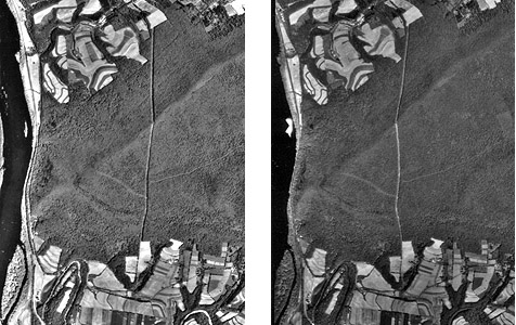
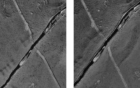
Below in Figure 6.14.2 are portions of two aerial photographs showing Little Mountain. The two photos were taken from successive flight paths. The two perspectives can be used to create a stereopair.
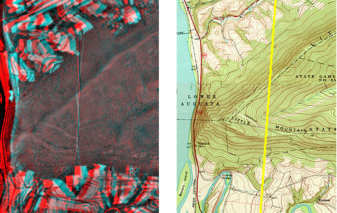
Next, the stereopair is superimposed in an anaglyph image. Using your red/blue glasses, you should be able to see a three-dimensional image of Little Mountain in which the power line appears straight, as it would if you were able to see it in person. Notice that the height of Little Mountain is exaggerated due to the fact that the distance between the principal points of the two photos is not exactly proportional to the distance between your eyes.
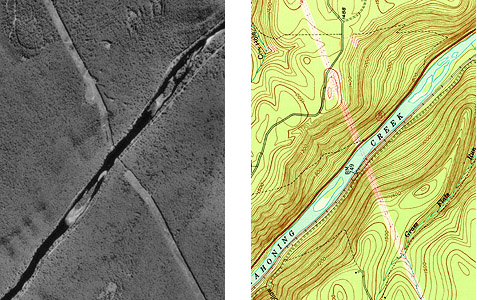
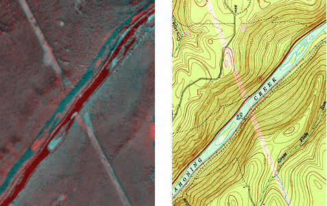
Let's try that again. We need to make sure that you can visualize how stereoscopic viewing transforms overlapping aerial photographs from perspective views into planimetric views. The aerial photograph and topographic map portions below show the same features, a power line clearing crossing the Sinnemahoning Creek in Central Pennsylvania. The power line appears to bend as it descends to the creek because of relief displacement.
Two aerial photographs of the same area taken from different perspectives constitute a stereo pair.
By viewing the two photographs stereoscopically, we can transform them from two-dimensional perspective views to a single three-dimensional view in which the geometric distortions caused by relief displacement have been removed.
Photogrammetrists use instruments called stereoplotters to trace, or compile, the data shown on topographic maps from stereoscopic images like the ones you've seen here. The operator pictured below is viewing a stereoscopic model similar to the one you see when you view the anaglyph stereo images with red/blue glasses. A stereopair is superimposed on the right-hand screen of the operator's workstation. The left-hand screen shows dialog boxes and command windows through which she controls the stereoplotter software. Instead of red/blue glasses, the operator is wearing glasses with polarized lens filters that allow her to visualize a three-dimensional image of the terrain. She handles a 3-D mouse that allows her to place a cursor on the terrain image within inches of its actual horizontal and vertical position.