Lesson 8: Drilling Engineering - Drilling Contracts, The Rig Crew, and Drilling Rigs
8.0: Lesson Overview
In this lesson, we will begin to discuss the drilling process. In particular, we will discuss:
- the life-cycle of a field or reservoir and the role of the drilling engineer in each phase of production;
- drilling contracts;
- personnel on a rig crew and personnel at the rig site; and
- types of drilling rigs.
We will also see that drilling engineers work on all tasks involving a drilling rig. Typical tasks performed by a drilling engineer include (but are not limited to):
- help to develop (as part of an Asset Team) well proposals for all wells drilled in a field or reservoir;
- help to develop workover proposals for wells requiring major rig workovers;
- combine the well proposals and major rig workover proposals to develop a rig schedule that ensures that the drilling company has enough rig work to warrant a long-term contract (this benefits their own company, the field operator, by having sufficient work to guarantee a long-term contract results in improved contracts rates);
- perform all drilling calculations (drilling fluid specifications, casing depth targets, cement properties, etc.) to develop the rig specifications for all of the work on the rig schedule to ensure the rigs under contract are capable of handling all work on the rig schedule;
- select all equipment: bit size and type, casing and connection grades, drill pipe grades, etc.;
- liaise with the drilling company and suppliers to ensure that off-the-shelf equipment/supplies and long lead time equipment/supplies are available at the appropriate times on the rig schedule;
- liaise with the local, state, and national governments to ensure that all permits are acquired; and
- work at the rig-site to look after the interests of the operating company.
We will see that operating oil and gas companies, even the large integrated major companies, do not drill their own wells. The drilling operations are typically contracted to drilling companies. The drilling contracts discussed in the lesson are:
- day-rate contracts
- turn key contracts
Finally, we will discuss the types of rigs available for drilling oil and gas wells. We will discuss cable tool rigs from an historical perspective and then discuss modern rotatory rigs. We will then finish the lesson by discussing the different rig-types available for off-shore operations.
Learning Objectives
By the end of this lesson, you should be able to:
- discuss the life cycle of a producing oil or gas field;
- describe the role of the drilling engineer during the life cycle of the field;
- compare and contrast the similarities and differences in exploration wells, appraisal wells, delineations wells, and development wells;
- list and explain some of the most important components of a well proposal;
- list and describe the role of a rig schedule in field development;
- discuss the difference between a day-rate drilling contract and a turn key drilling contract;
- list important terms in a day-rate contract;
- list the job responsibilities of key members of an onshore rig crew including:
- drilling contractor personnel;
- operating company personnel;
- service company personnel;
- list the job responsibilities of key members of an offshore rig crew;
- differentiate between a cable tool drilling rig and a rotary drilling rig;
- explain the differences and pros and cons of rotatory table drilling rigs and a top-drive drilling rigs;
- list the major components of a modern drilling rig; and
- identify the differences in the available off-shore drilling rigs.
Lesson 8 Checklist
| To Read | Read the Lesson 8 online material | Click the Introduction link below to continue reading the Lesson 8 material |
|---|---|---|
| To Do | Lesson 8 Quiz | Take the Lesson 8 Quiz in Canvas |
Please refer to the Calendar in Canvas for specific time frames and due dates.
Questions?
If you have questions, please feel free to post them to the Course Q&A Discussion Board in Canvas. While you are there, feel free to post your own responses if you, too, are able to help a classmate.
8.1: Introduction
The typical life-cycle of most oil or gas fields can be classified into five stages:
- Exploration Stage
- Appraisal/Delineation Stage
- Development Stage
- Plateau Stage
- Decline Stage
- Abandonment Stage
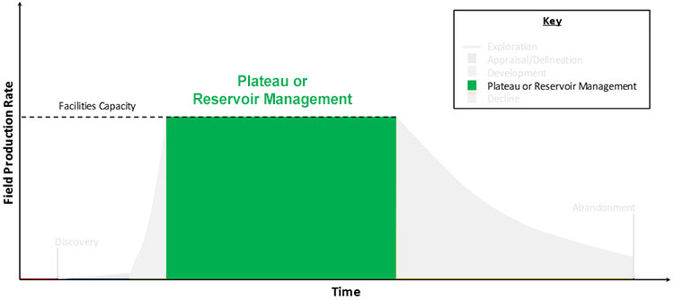
Life Cycle of an Oil or Gas Field or Reservoir
The life-cycle is illustrated in Figure 8.01. Drilling engineers are essential during all stages of this life-cycle.
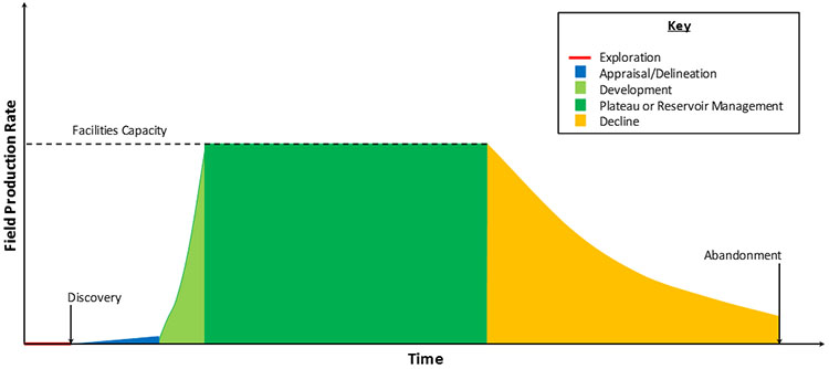
The life-cycle of an oil or gas field starts with Exploration Stage where undrilled acreage is evaluated to determine its potential for future commercial development. During the exploration stage of field development, Exploration Geologists and Geophysicists (amongst others) develop prospects which look promising for future evaluation. Once these prospects are generated, exploration wells are drilled to prove whether hydrocarbons actually exist at the locations identified by the geologists.
The statistical success rate of exploration wells (exploration wells finding commercially viable hydrocarbon reservoirs) is between 25 – 45 percent[1]. Once a well encounters a crude oil or natural gas reservoir, that well is designated the Discovery Well for the reservoir. This starts the beginning of the Appraisal and Delineation Stage of the field development.
During the Appraisal and Delineation Stage of the field development, wells are drilled to provide data for the Development Geologists to evaluate the newly discovered reservoir. Wells drilled in the interior of the reservoir are referred to as Appraisal Wells and are used to gather information from Core Analysis, Well Logging, and Well Tests that can be used to analyze important reservoir properties and create trend maps of these properties, such as, depth, thickness, porosity, water saturation, permeability, etc. Wells drilled towards the periphery of the reservoir are referred to as Delineation Wells and are used determine the areal extent and size of the reservoir. During this stage in the life-cycle, the appraisal and delineation wells produce limited amounts of hydrocarbons. Oil or gas production, when it occurs during the appraisal and delineation stage, is typically limited to the volumes produced during well tests where the wells are allowed to flow for limited periods of time (several days) to determine the production rates that can be anticipated from the reservoir. Additional fluids may be produced if an Extended (long-term) Well Test or if a Pilot Test is run during the appraisal and delineation period.
Once the development geologists and reservoir engineers feel that the reservoir has been adequately appraised and delineated, the Development Stage begins. In the development stage, all of the wells required for initial Field Development Plan are drilled, completed, and tied back to the production facilities. During this period, multiple drilling rigs may be running simultaneously in order to drill and complete all of production wells, injection wells, and, possibly, observation wells required by the development plan in a timely manner.
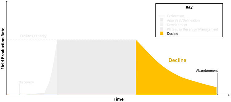
After the field has been put onto production, the wells produce into production facilities which have a fixed capacity. If the production potential from all of the development wells exceeds the production capacity of the surface facilities, then production will be limited by the capacity of the production facilities. (In other words, the facilities act as a bottleneck in the system, and the wells must be produced below their potentials). As reservoir pressure is depleted, the potential production capacity of the wells declines (due to the reduced drawdown), and they can no longer produce oil at the full capacity of the facilities. (In other words, at some time, the reservoir pressure declines to the point where the wells become the bottleneck in the system.)
The early period of production, when the facility capacity is the bottleneck, is often referred to as Plateau Stage of production because the facility capacity is relative constant over time (barring any upgrades or additions to the facilities). The later period of production, when the well capacity is the bottleneck is referred to as the Decline Stage of production because the well capacity is tied to the reservoir pressure which is continually decreasing with time. Both of these stages are illustrated in Figure 8.01.
While being the more common name, I personally do not like the term “Plateau Stage” because this has somewhat of a passive sound to it. In order to keep the facilities producing at capacity, there is a lot of activity that needs to be performed behind the scenes. From the start of production, the reservoir pressure will decline due to fluid withdrawals. In addition, as time increases, unwanted water or gas production may increase and Well Interventions (Workovers). To keep oil production at the facilities capacity, Infill Wells may need to be drilled; completion designs may need to be altered; wells may need to be stimulated; water or gas shut-off workovers may become necessary; artificial lift may be required, secondary production techniques may be used; etc. So, during this plateau stage, a lot of reservoir management activities may be required to keep the facilities fully utilized. Therefore, I prefer to call this period the Reservoir Management Stage or Managed Plateau Stage of production.
At some point in time, the reservoir management options can no longer keep production at the facilities capacity, and the field production rate will eventually go into decline. During this stage, reservoir management activities are still performed, but with the objective of arresting the decline rate, not keeping the facilities fully utilized.
Finally, at some finite, non-zero production rate, the revenues generated by the oil and gas sales can no longer support the costs of the operations, and the field must be abandoned. This stage is referred to as the Abandonment Stage of the field.
As stated above, drilling engineers are required during all stages of this life-cycle.
[1] Energy Information Administration / OGJ.
8.1.1: Exploration Phase
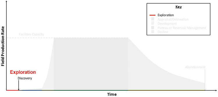
As discussed earlier, the exploration geologist and geophysicist (amongst others) generate locations for future exploration prospects. Once exploration prospects are generated, drilling engineers work with the exploration geologists to develop the drilling proposal(s) for any Exploration Wells. Exploration wells are wells which are drilled with an objective of proving or disproving the presence of commercial hydrocarbon accumulations. A popular slang term for the first Exploration Well drilled in a geologic basin or region is a “Wildcat Well”.
The drilling proposal is a plan for the well. Normally, an exploration geologist and the drilling engineer take the joint lead role in the development of the well proposal. This proposal typically includes:
- the objectives of the well (the reasons for drilling the well)
- the proposed drilling rig to be used for the well
- the surface location of the rig site (latitude and longitude)
- the well target:
- the bottom-hole location (latitude and longitude) of the well
- the target depth(s) of the well
- directional drilling information
- the wellbore diameter and depth of the wellbore (wellbore diameters will change during drilling operations due to changes in drill bits)
- the specifications for all bits required during drilling operations
- the anticipated geologic cross-section and stratigraphic column during drilling operations
- the pore-pressure profile anticipated during drilling operations (pore pressures versus depth)
- the fracture pressure profile anticipated during drilling operations (formation fracture pressures are the pressures at which the rock will mechanically fail – fracture)
- the casing design and specifications for the well
- the drilling fluid (mud) design for the well
- the well control and safety procedures for the well
- the required data acquisition that is essential for the exploration geologist to appraise the well
- the anticipated time required to drill the well (depth versus time forecast)
- cost estimates for the well:
- one estimate for an unsuccessful well (no hydrocarbons discovered)
- one estimate for a successful well (hydrocarbons discovered) which may include completion costs and additional data acquisition cost (well logs, core data, etc.)
Once a drilling proposal is generated and approved, the drilling engineer coordinates with the drilling companies, service companies, suppliers, and manufactures for all of the equipment required by the well. Some of this equipment may can be purchased “off the shelf” and can be delivered in a relatively short time; while other equipment (Long Lead Time Equipment) may need to be manufactured to specifications developed specifically for the well. This long lead time equipment may take over a year for delivery. The logistics of coordinating the on-time delivery of the equipment for the well is the responsibility of the drilling engineer.
Drilling engineers also interact and coordinate with the company’s Health, Safety, and Environment (HSE) Departments and government permitting agencies to ensure that the well meets the company’s and the government’s HSE guidelines and that all of the government permits are properly obtained.
Only after the required equipment is onsite (or guaranteed to be delivered on time) and all permits are in hand can drilling operations begin. Again, a drilling engineer takes the lead role in all drilling operations. Whenever a drilling rig is required for some operation (drilling, cementing, Major Rig Workover (MRWO)), a drilling engineer will take the lead. Depending on the organization of the company, the drilling engineer who designed the well may not necessarily be the drilling engineer in charge of drilling the well. A company may be organized in a manner where Staff Drilling Engineers are working with the exploration geologists developing drilling proposals and developing the plans and logistics for the wells, while Field Drilling Engineers are drilling the wells.
8.1.2: Appraisal and Delineation Phase
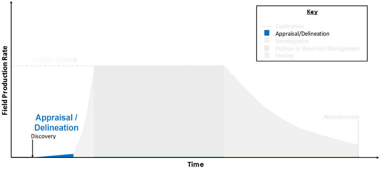
Appraisal and delineation wells are wells with at least one objective of gaining data to improve the understanding of the reservoir. During this phase of the life-cycle, a rig schedule is typically developed with input from most Asset Team members, but most notably the drilling engineer(s), the development geologist(s), and the reservoir engineer(s). The rig schedule prioritizes the wells to be drilled based on the objectives of the well and the logistics of the well (availability of off-the-shelf equipment and the need for long lead time equipment).
During the appraisal and delineation period, the drilling engineers continue to work with the development geologists to create the drilling proposals. During this phase of the life-cycle, the rig schedule is heavily weighted with drilling activity; however, Plugging and Abandoning (P&A) and Temporary Well Suspension (mothballing the wells for future use as development wells) activities are also included.
During this period, a learning curve for drilling the wells is formed, as the geologic formations to be drilled through and the Drilling Penetration Rates through these formations become understood. Often, this learning curve is applied to the Development Plan and economics of the field or reservoir.
If multiple drilling rigs are available for the project, then the different appraisal and delineation wells in the rig schedule are prioritized and assigned. On the other hand, if a single rig or several rigs are servicing multiple projects, then gaps in the rig schedule are assigned to a project to allow for the timely interpretation of data from a well, so that future wells and well proposals can benefit from that data.
8.1.3: Development Phase
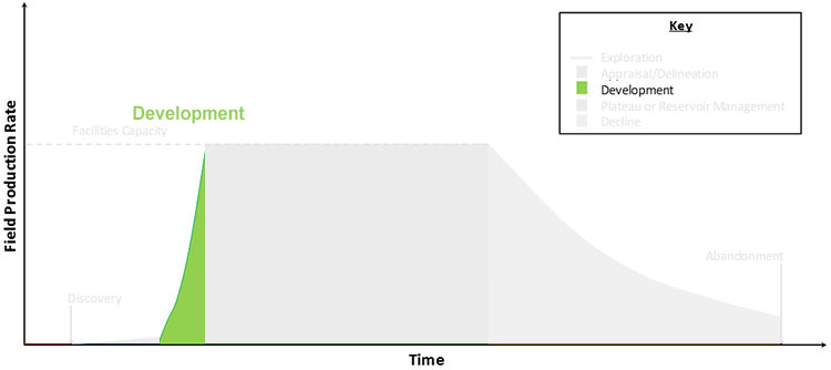
During the development phase, wells are drilled with the primary objective of hydrocarbon production. This is the phase in the field or reservoir life-cycle where the development plan is implemented. There is a strong economic incentive (time value of money) for developing the field or reservoir.
During the development phase of the life-cycle, the rig schedule is almost exclusively dedicated to drilling the wells considered in the original development plan. During development drilling, the learning curve becomes steeper (more is learned over a shorter period) and the drilling times typically become shorter as the drilling engineers and drilling crews make use of the lessons learned from previous wells.
8.1.4: Plateau Phase
As stated earlier, during the Plateau Phases of the field life-cycle, multiple Reservoir Management activities occur. If the field or reservoir is being developed with a Phased Development (development performed in distinct phases), then the drilling of wells required in the later phases of the development occurs.
During this phase, the drilling rig is often used for activities other than drilling. As discussed in earlier, the production of unwanted fluids from the reservoir may require the drilling rig to be used for major rig workovers. These MRWOs require the use of the rig to perform well remediation activities that cannot be performed using a Slickline (a non-electrical conducting wire used to run workover tools), a Wireline (an electrical conducting wire used to run these tools), or coiled tubing (tubing wound on large spools which can be run using a non-rig Coiled Tubing Unit). Workovers requiring a MRWO include some Secondary Cementing Operations (repairing poorly cemented casing sections that were not properly cemented during the original – or Primary Cementing Operations or Squeeze Cementing Operations – Zonal Isolation technique of forcing cement into perforation intervals producing unwanted fluids), pull tubing for tubing change-out operations, pulling the tubing and completion to recomplete the well, deepening the well, milling operations, etc.
8.1.5: Decline Phase
Later in the life of the field or reservoir, the drilling of additional new wells may be required after all phases of the original development plan have been completed and the reservoir management activities focus on arresting the reservoir decline. For example, in order to arrest the declining oil or gas production rates, Infill Drilling may be applied. Infill drilling is a method where the original drainage areas are reduced by drilling new wells between two or more existing wells. Also, in oil reservoirs, Pattern Realignment may be used in Secondary Recovery Operations (gas or water injection) to adjust the producer-injector patterns to recover any oil not recoverable from the original patterns.
As stated earlier, all oil and gas field activities that require a drilling rig are planned and supervised by drilling engineers. As such, the role of the drilling engineer spans the entire life span of the field or reservoir from exploration to decline and abandonment.
8.2: Drilling Contracts
Many people are surprised to learn that the large oil and gas companies that they see in the news or purchase their gasoline from do not drill their own wells. The actual drilling of wells is typically performed by a Drilling Company or Drilling Contractor that specializes in drilling operations. These drilling companies have the expensive equipment (drilling rigs), personnel, and expertise for performing the complex activities associated with oil or gas well drilling. In almost all cases, a Field Operator or Field Operating Company (the oil or gas company operating the field and requiring the services of a drilling company) will develop a contract with a drilling contractor to drill wells in the field. To minimize rig transport time (and cost) and to develop reasonable terms for a good long-term contract, field operators will normally develop a one- to two-year queue of desired work to guarantee to the drilling company. Therefore, the contracting process is performed after the field operator has a mature, robust plan for the field or lease development and a viable rig schedule.
There are many contract types used in the oil and gas industry, but two of the more common contract types are the Day-Rate Contract and the Turnkey Contract. Of these two contract types, the day-rate contract is the more common contract.
In a day-rate contract, the drilling engineers for the operating company design the well, and the operating company leases the drilling rig, its personnel, and routine supplies at a fixed daily rate (Day Rate) from the drilling contractor. This day rate may or may not include fuel (depending on the terms of the contract) and does not include the costs of Capital Goods or special services (such as well logging, cementing, or stimulation). Capital Goods or Tangible Drilling Supplies are tangible items required for the well, such as Casing, Tubing, Completion Equipment, Down-Hole Pumps, etc. (the term “tangible items” refers to items that can literally be touched). Typically, the day rate accounts for approximately one half of the costs required to drill the well. The Total Daily Cost required to drill a well is referred to as the Spread Rate.
To summarize, in a day-rate contract, drilling engineers working for the operating company design the well and plan all of the equipment specifications. In addition, the operating company leases the rig and its rig crew at a specified daily rate (day rate) which accounts for approximately one half of the daily expenditures. The actual daily rate to drill the well is the spread rate.
In a turnkey contract the operating company pays the drilling contractor to design and drill the well for a fixed cost. Thus, the operating company provides the objectives of the well, the desired data acquisition program for the well, the surface location of the well, the bottom-hole location of the well, and the target depth(s) of the well. Drilling engineers working for the drilling company then design and execute the well and coordinate all service work with the Service Companies.
8.3: Rig Personnel
While drilling a well, drilling operations continue 24/7. This is because the drilling contractor would like to maximize the use and revenue from the drilling rig, and the operating company is paying for the rig on a daily basis (for a day-rate contract). Therefore, multiple rig crews are required to run a rig continuously during drilling operations, and multiple companies may be performing Simultaneous Operations (SIMOPS) at various points in the drilling process.
The personnel involved in drilling an oil or gas well include:
- 8.3.1: Drilling Contractor Personnel (Land Rigs)
- 8.3.2: Drilling Contractor Personnel (Offshore Rigs)
- 8.3.3: Operating Company Personnel
- 8.3.4: Service Company Personnel
8.3.1: Drilling Contractor Personnel (Land Rigs)
- Tool Pusher:
The drilling company employee in charge of all drilling and non-drilling operations occurring on and around the drilling rig. He/she is the lead, onsite representative of the drilling contracting company. In addition, the tool pusher is the key contact between the drilling contracting company and The Company Man (lead wellsite representative of the operating company). The Drillers (below) report to the tool pusher. From the drilling company’s perspective, the tool pusher is the principal representative in charge of the safety and environmental aspects of the drilling operations. - Drilling Crew:
- Driller:
The drilling company employee in charge of drilling operations and supervision of a drilling crew. The driller reports to the tool pusher. - Derrickman (one per crew):
The derrickman is typically second in rank in a drill crew behind the driller (Some large offshore drilling crews may have a position of assistant driller ranked between the derrickman and the driller.). In old movies or documentaries, you may have watched scenes of a person working at the top of the Derrick of a drilling rig who is manually moving and handling Drillpipe; this is the derrickman. Historically, this would have been one of the more physically demanding and dangerous jobs on the rig crew. Most modern drilling rigs have automated pipe-handling equipment to preserve safe procedures during current drilling operations. - Roughnecks (several per drill crew):
Experienced members of a drilling crew who may work on the rig floor or up on the derrick. Typical tasks for a roughneck include tending to engines and pumps during operations, coupling or uncoupling Stands of Drillpipe during Tripping Operations into or out of the wellbore, and racking or unracking drillpipe. - Skilled Technicians:
Mechanics, electricians, crane operators, welders, etc., for operating and maintaining specialized rig equipment. - Roustabouts (several per rig crew):
General laborers working on or around the drilling rig. These are entry level jobs on a drilling rig and, in some companies, may be available for summer internships to engineering students. Typical tasks for a roustabout may include unloading, lifting, and hauling materials and supplies used for drilling operations, cleaning and maintaining the rig site (picking up litter, weeding, mowing the grass at the rig site, etc.), maintaining the roads (clearing brush and debris), etc.
- Driller:
8.3.2: Drilling Contractor Personnel (Offshore Rigs)
When drilling offshore, additional crew members are required to handle the marine operations related to the drilling rig. These additional crew members include:
- Offshore Installation Manager:
The Offshore Installation Manager, or OIM, is the chief executive on the offshore installation. The OIM is the final authority for all decisions made on the installation. The operations that are performed under the supervision of the OIM include Drilling Operations, Marine Operations, Mechanical Services, Electrical Services, and Hotel Services. Often, the position of the OIM is assigned to former naval officers or highly experienced offshore tool pushers. - Tool Pusher:
The role of the tool pusher on an offshore installation is identical to that of his/her onshore counterpart. The tool pusher is responsible for all drilling operations. - Barge Master:
The Barge Master (and his/her crew) is responsible for all marine operations that occur on a Mobile Offshore Drilling Unit (MODU). An MODU is drilling rig placed on a mobile marine vessel, such as a ship or barge, that can be moved onto the surface location of the well by either towing or by self-propulsion. The barge master is equivalent to a ship’s captain and is responsible for all marine operations including navigation, hull and deck maintenance, crane operations, helicopter operations, radio operations, supply logistics, etc. - Chief Mechanic:
The Chief Mechanic (and his/her staff) oversees the Mechanical Department and is responsible for the maintenance of all mechanical equipment. - Chief Electrician:
The Chief Electrician (and his/her staff) oversees the Electrical Department and is responsible for the maintenance of all electrical equipment. - Camp Boss:
The Camp Boss (and his/her staff) is responsible for all hotel services on the offshore installation. Work crews on an offshore installation typically work on 7/7, 14/14, or 28/28 day on-duty/off-duty schedules. During their on-duty time on the offshore installation, they must be housed, fed, entertained, etc. The camp boss is responsible for maintenance of all office space, living accommodations, galley (kitchen) services, laundry services, and entertainment services on the offshore installation.
8.3.3: Operating Company Personnel
- Drilling Superintendent:
The operating company employee in charge of drilling operations. The drilling superintendent typically works in a field office away from the rig site and supervises simultaneous drilling operations of multiple wells. The rig-site company man reports to the drilling superintendent. From the operating company’s perspective, the drilling superintendent is the principal representative in charge of the safety and environmental aspects of the drilling operations. The position of the drilling superintendent is typically given to experienced drilling engineers. - Wellsite Personnel:
- Company Man:
The operating company representative at the rig site. This function is typically handled by an experienced drilling engineer or wellsite geologist who looks after the interests of the operating company. In addition, the company man liaises with the tool pusher to ensure the well plans are carried out to the operating company’s specifications and safety standards. - Wellsite Geologist:
An operating company geologist who reviews the geologic progress of the well as it is being drilled. Typical tasks performed by a wellsite geologist include planning and reviewing well logs during Well Log Operations (well logs are records of geological data versus depth used by geologists to evaluate a well); reviewing Logging while Drilling (LWD) or Measurement while Drilling (MWD) data if available (LWD and MWD are relatively recent developments that include logging equipment on the Bottom-Hole Assembly (BHA) of the drill string and are used to obtain real-time logs of the wellbore.); and Mud Logging (the analysis of rock cuttings as they are brought up-hole by the Drilling Fluid or Drilling Mud. The main roles of the wellsite geologist are to keep the company man and drilling superintendent appraised of the progress of the well (particularly as it approaches the reservoir targets), to inform the driller and company man when important geologic Marker Beds may be encountered so new drill bits or drilling fluids can be made ready, and to provide written reports and records to development geologists to aid in their interpretations of the well and reservoir.
- Company Man:
8.3.4: Service Company Personnel
In addition to the operating company and the drilling company, specialized companies, called Service Companies, provide specific well services at the rig-site during certain operations. The service company personnel also form an integral part of the well drilling team.
- Drilling Fluids Engineer or “Mud Man”:
The Drilling Fluids Engineer (often referred to as “a Mud Man”) is a wellsite specialist who ensures that the properties of the Drilling Fluid (often referred to as “Mud”) meet the specifications for the section of the wellbore that is currently being drilled. As the well depth increases, the specifications of the drilling fluid will change as the rock and fluid properties encountered by the well change. The drilling fluids engineer ensures that (1) the Mud Pumps are operating properly, (2) any drilling fluid additives are onsite and are capable of achieving the specifications required by the current and future sections of the wellbore, and (3) all additives are added at the appropriate times (or, if required, the mud is switched out entirely) when well conditions change. The term “mud” is used in oil and gas well drilling because historically the most common water-based drilling fluids were mixtures of water and finely ground, bentonite clays which, in fact, are muds. - Cement Engineer:
The Cement Engineer is a wellsite specialist who ensures that (1) the Cement Pumps are operating properly, (2) cementing operations are performed in a safe manner and are capable of achieving the cementing objectives of the well, (3) the cement properties (rheology, fluid loss, slurry thickening time, slurry setting time, etc.) meet the specifications required for the cementing operation, and (4) cement additives are onsite and can achieve the desired cement properties. During the oil and gas well drilling, Casing must be cemented into place to protect the environment from the wellbore (and to protect the wellbore from the environment). Casing is steel pipe used to isolate the environment from the wellbore and from the drilling operations. During cementing operations, a cement slurry is pumped downward through the interior of the casing and then upward through the annular space between the wellbore and the outer diameter (O.D.) of the casing. The cement is then allowed to set in this annular space. - Logging Engineer:
As discussed earlier, Well Logs or Open-Hole Logs are run periodically during drilling operations (prior to the setting of casing – most importantly over the producing intervals prior to the installation of the production casing string or liner). Well logs are records from measuring devices that are used to evaluate certain properties of the downhole rocks. The logging engineers make sure that all logging equipment is working properly and that all logging tools are accurately calibrated. Typical processes logs measure reservoir properties such as porosity, fluid saturations, and permeability (after calibration with well logs or well tests). - Well Test Engineer (Optional):
Once a well has reached its target formation(s), it may be tested with a Drill Stem Test (DST). In a drill stem test, the formation of interest is isolated using a temporary completion, and fluids are produced through the drill pipe or a DST string. The well is flowed at a predetermined rate-time schedule to estimate reservoir characteristics such as reservoir pressure, reservoir permeability, and anticipated production rates. The main objective of a DST is to determine whether the well is economically viable and warrants a permanent completion or whether the well should be Plugged and Abandoned (P&A’ed). Drill stem tests are typically run on Exploration Wells or Appraisal Wells where reservoir properties may not be fully understood. In Development Wells in reservoirs with known property ranges and property trends, DSTs may not be required to determine whether a well should be completed or not, and that decision can be made from open-hole logs. - Well Completions and Stimulation Engineers:
Once a well has reached its target formation(s) and the decision to complete the well has been made, the well is completed and stimulated (not all wells are stimulated). As we discussed in earlier lessons, stimulation refers to the process of Acidizing or Hydraulically Fracturing (Frac’ing) the well in order to improve the flow conditions near the well. Due to the controversies associated with the hydraulic fracturing process, you may have seen photos or videos of wells being hydraulically fractured in the news or on the Internet. The completions and stimulation engineers coordinate the completions operations with the tool pusher and company man, ensure that the completion or stimulation process meets the objectives of the well, and supervise the crews performing the work. Typically the role of a completions engineer is assigned to a production engineer.
8.4: The Drilling Rig
8.4: The Drilling Rig section of this lesson will cover the following topics:
Note: You can access specific subsections of the lesson by clicking on the links above or continue reading through the lesson using the link below.
8.4.1: Cable Tool Rigs
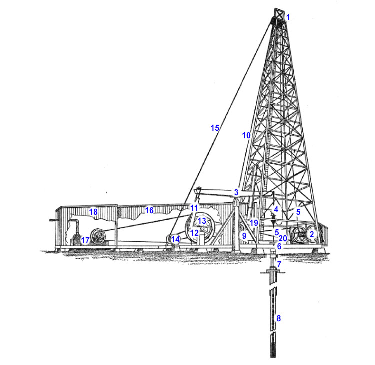
Cable tool rigs were the first drilling rigs used for hydrocarbon wells. They were used in the United States in the second half of the nineteenth century (1800s) to drill shallow hydrocarbon wells in the Appalachian Region. While these rigs are no longer used in modern oil and gas well drilling, they are of historical note. Cable tool rigs were originally used in the United States for drilling water wells in the early 1800s but had their origins in the percussive drilling techniques used by ancient Chinese and Persian civilizations. They were adapted in the mid- to late-1800s for drilling hydrocarbon wells. Figure 8.02 provides an illustration of a cable tool drilling rig.
| Diagram | Index |
|---|---|
 |
|
| Cable-tool drilling is done by raising and dropping a string of tools on the end of a cable. The up and down motion is imparted by the walking beam. The tools are pulled from or lowered into the hole by winding or unwinding the drill cable on the bull wheel. Casing is raised or lowered by the casing line and calf wheel. The cuttings are removed from the hole by the bailer, which is raised and lowered by the sand line and reel. | |
| Source: Ball, M. W.: This Fascinating Oil Business, The Bobs-Merrill Company, p. 103 (Cable Tool Drilling Rig [11]) |
|
The cable tool itself is essentially a heavy metal chisel that is suspended from a wire cable which, in turn, is attached to a spring pole or Walking Beam (similar to a lever and fulcrum system). The cable tool is repeatedly raised, using the spring pole or walking beam, and allowed to drop (free fall) down the wellbore causing the rock to fail at the point of impact at the bottom of the hole. When enough rock fragments accumulate at the bottom of the wellbore, water is poured into the hole, and Bailers are lowered to remove the rock cuttings and debris.
Historically, bailers were simply buckets used to lift the debris from the wellbore to the surface. Modern bailers are tools which are run on wireline or slickline with a sealed compartment at low pressure. When the compartment is opened, the surge of fluids at hydrostatic pressure into the low-pressure chamber carry the sand and drilling debris into the bailer. The tool is then lifted to the surface.
Cable tool rigs are of historical note because Colonel Drake’s well in Titusville, PA (considered the first well drilled with the specific objective of producing oil) was drilled with a cable tool rig in 1859 to a depth of 69.5 ft. The drilling of Drake’s Well is considered to be the start of the modern oil and gas industry. Cable tool rigs began to be replaced with rotary drilling rigs in the 1890s.
8.4.2: Rotary Rigs
As previously mentioned, rotary rigs began to replace cable tool rigs in the late 1890s. The discovery well for the prolific Spindletop Oilfield in Beaumont, TX was drilled to a depth of 1,039.0 ft with an early rotary rig in 1901 (Spindletop discovery date was January 10, 1901).
In a rotary rig, torque (rotation) is applied to the Drill Pipe or Drill String (hollow steel tubing) with a drill bit attached to the end of the Bottom-Hole Assembly (BHA). As the name implies, the bottom-hole assembly is attached to the bottom end of the Drill String, nearest to the formation being drilled. The drill string is the combined length of drill pipe extending from the rotary system on the drilling rig to the bottom-hole assembly at the bottom of the wellbore). The BHA contains all of the equipment required to drill the current section of the wellbore. This equipment may include Drill Collars (heavy steel tubing used to add weight to the drill bit), directional drilling equipment, LWD or MWD tools, etc.
There are several ways to classify rotary drilling rigs. However, in this class, we will classify them by the location on the rig of the Rotary System. The Rotary System is one of the major systems on the drilling rig and is where the torque is applied. We will discuss two types of rigs with two different rotary systems: a conventional rotary table rig and a top-drive rotary rig.
The following pages will discuss two types of rotary rigs.
- 8.4.2.1: Conventional Rotary Rig or Rotary Table Rig or Kelly Drive Rig
- 8.4.2.2: Top-Drive Rig
8.4.2.1: Conventional Rotary Rig or Rotary Table Rig or Kelly Drive Rig
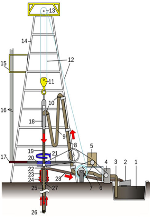
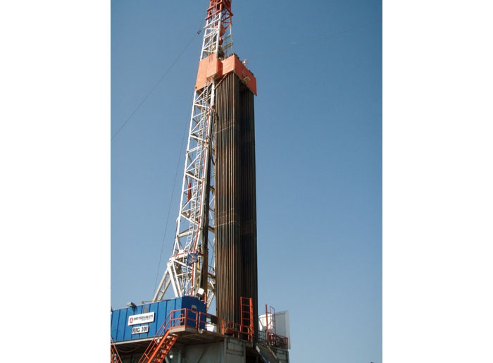
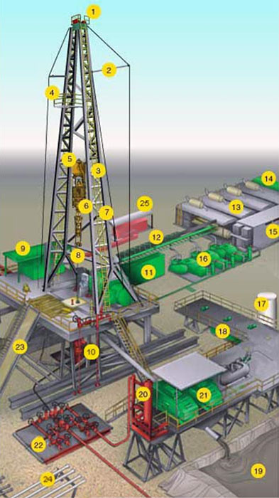
A conventional rotary rig or rotary table rig or kelly drive rig is a drilling rig where the rotation of the drill string and bit is applied from a rotary table on the rig floor. The conventional rotary rig was the most common rig used during the past century (1900s) and is the drilling rig that you are probably most familiar with from old movies and documentaries. A schematic of a conventional rotary drilling rig is shown in the schematic diagram in Figure 8.03.
| Diagram | Index |
|---|---|
 |
|
| Source: D.T.E. Drilling Components of a Land-Based Rotary Drilling Platform [12] | |
As identified in this figure, the Derrick or Mast (Item 14) is the tall steel structure with its base on the rig floor. On the rig floor the Kelly (Item 19), the Kelly Bushing (not shown), and the Turn Table or Rotary Table (Item 20) are also identified in this figure. These are the components of the Rotary System that provides the torque to the drill string on a conventional rotary rig. A photograph of an actual kelly, kelly bushing, and turn table / rotary table is provided in Figure 8.04(A) while a schematic diagram of the entire assembly is shown in Figure 8.04(B) .
The kelly is a hollow square or hexagonal piece of pipe through which the drill pipe can be passed. This is the pipe marked (I) in Figure 8.04. The kelly is matched to a similarly shaped bushing (square or hexagonal), the kelly bushing, marked (II) in Figure 8.04 which is raised above the rig floor. You can think of the kelly as a hollow square or hexagonal bolt and the kelly bushing as a matching square or hexagonal wrench that turns the bolt. The kelly bushing is set into the master bushing, marked (III) in the photo, with four large metal pins, which in turn sits in the rotary table, marked (IV) in the photo. The rotary table provides the torque required to rotate the master bushing, kelly bushing, kelly drill pipe, and drill bit. The slight rotational blur in the photo implies that the rotary table and kelly were rotating when the photo was taken.
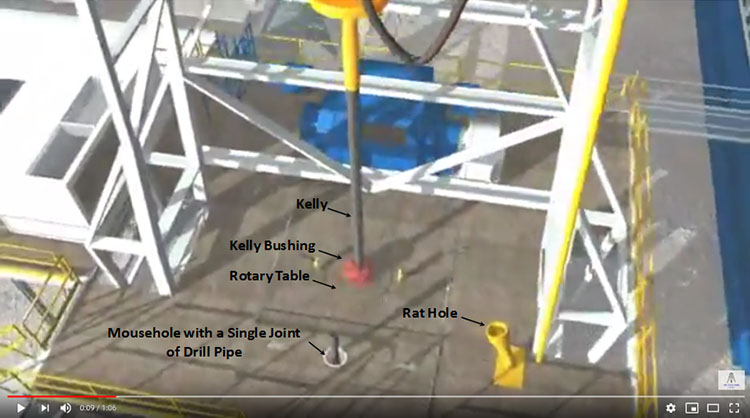
Also shown in Figure 8.04(A) is the Mousehole, marked as (V) in the photo, along with a Joint of Drill Pipe (painted yellow in the lower left-hand corner). The mousehole is the temporary storage location for the next Joint of Drill Pipe to be added to the Drill String. A joint of drill pipe is a 30-foot piece of pipe that is the basic element of the Drill String. Oil and gas companies purchase drill pipe from the steel companies by the joint. Typically, two (a Double) or three (a Triple) joints of drill pipe are connected to form a 60-foot or 90-foot Stands of drill pipe that are racked and stored on the side of the derrick as shown as Item 16 in Figure 8.03 and in the photo in Figure 8.05. Note that the Mousehole is not the same as the Rat Hole (Item 21) in Figure 8.03. On the rig floor, the rat hole is a hole on the rig floor with a large diameter piece of casing extending above the rig floor that is used to temporarily store the kelly when it is disconnected.
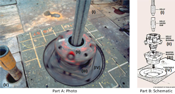
Source (Part B): Drilling Formulas: What is Kelly Rig? [14]
8.4.2.2: Top-Drive Rig
Figure 8.06 shows a schematic diagram of a typical top-drive rig. In a top-drive drilling rig, the top-drive (Item 6 in Figure 8.06) is suspended from the traveling block (Item 5 in Figure 8.06) and attached to a guide system (gear train and rail system) on the derrick. The top-drive is an electrical motor that has the ability to travel vertically up and down and to impart torque to the drill pipe. These drilling rigs began to appear in the late 1990s. Although the top-drive supplies the torque for the system, a rotary table is still used to supply stability to the drill string and as a redundant (back-up) rotary system.
The advantages of a top-drive rig are that longer sections of drill pipe can be (1) connected to the drill string when the rig crew is drilling ahead, (2) connected to the drill string when tripping into the hole, or (3) unconnected from the drill string when tripping out of the hole.
As we saw in our discussion of a Conventional Rotary Table Rigs, the next 30-foot joint of drill pipe to be added to the drill string is temporarily stored in the mousehole on the rig floor. This joint of drill pipe is added to the drill string when drilling ahead or tripping into the wellbore. Tripping is the process of running drill pipe into or out of the hole for purposes other than drilling ahead. For example, if a drill bit needs to be changed due to wear, then the entire drill string needs to be pulled from the wellbore (tripping out of the hole), the drill bit needs to be replaced, and the drill string needs to be run back into the wellbore (tripping into the hole) to resume normal drilling operations. You can imagine how much ineffective rig time (in terms of not drilling ahead) is used tripping into or out of the wellbore and making or breaking connections in the drill string–particularly if the well's TD (Total Depth) is 10,000–15,000 feet (or a shallower well has a 10,000-foot horizontal section).
| Diagram | Index |
|---|---|
 |
|
| Source: United States Department of Labor - Oil and Gas Home - Illustrated Glossary Drilling Rig Components [17] Note: On the website linked above, you can select a name from the list or a number on the graphic to see a definition and a more detailed photo of the object. |
|
I would recommend that you go to the website and use the links to get a description of each component of the rig.
The improved efficiencies coming from a top-drive is that an entire 90-foot stand (or triple) of drill pipe can be connected to the drill string rather than a single 30-foot joint. This is because the top-drive can go to the full height of the derrick using the traveling block to connect to the entire stand of drill pipe. Note, however, that not all top-drives use a triple when connecting drill pipe; some use a Double (two joints), while others use a single joint from a mousehole.
Many of the concepts that we have been discussing are best illustrated with a series of YouTube videos and screen captures.
The Drill Training - Run drill pipe through rotary table YouTube clip (1:07) is an animation of how drill pipe connections are made on a conventional rotary rig. As I mentioned, on a conventional rotary table rig, only one joint (30 feet) of drill pipe can be added to the drill string at one time.
Highlights from this video include:
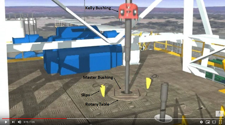
- Figure 8.07: Screen Capture at 9 seconds into the video: Rig Components
- Figure 8.08: Screen Capture at 19 seconds into the video: Use of Slips
- Figure 8.09: Screen Capture at 23 seconds into the video: Use of Mechanical Tongs
In the screen capture shown in Figure 8.07, we see many of the components discussed in this lesson: the kelly, kelly bushing, rotary table, mousehole, and rat hole. Throughout the video, you can see these components of the rig used in action.
In the screen capture shown in Figure 8.08, we see the slips (yellow). As shown in the video, the slips are used to suspend the drill string when it is disconnected from the rig’s hoisting system.
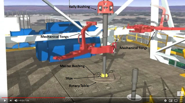
In the screen capture shown in Figure 8.09, we see the mechanical tongs (red). As shown in the video, the mechanical tongs are used to grip the kelly and drill string to aid in uncoupling (unscrewing) the two.
The A Drill Pipe Connection YouTube clip (5:42) below is of several Roughnecks (discussed earlier in this lesson) on an actual rig crew performing the same operations that you saw in the animation. Again, these tasks are being performed on a conventional rotary table drilling rig.
At several points in the video you can see a roughneck Throw Chain around the drill pipe. The Winding Chain is used to apply the torque that is used to screw or unscrew the threads in the drill pipe to couple or uncouple the joints.
What I like about this clip, and the reason that I selected it, was because of the “non-standard operating procedure” that seems to be occurring in the video. Did you spot it?
At around 2:52 into the video, it appears that while two of the roughnecks were trying to remove the slips from the master bushing, the hoist system on the derrick was attempting to assist them by lifting the kelly and drill pipe to release pressure from the slips. Instead of freeing the slips, the hoist appears to have lifted the entire section of the rig floor covering the rotary table, along with the two roughnecks. You can hear someone laughing in the video.
At around 3:31 into the video, one of the roughnecks and the hoist appear to use a piece of drill pipe to tamp the section of rig floor back into place. This piece of drill pipe is then placed into the mousehole as the next piece of drill pipe to be connected to the drill string. This is not a standard operating procedure on the rig floor. After this incident, you can see the rotary table and kelly bushing rotating in the manner discussed in these lesson notes.
In the tripping pipe with top drive YouTube clip (5:12), we will now see a rig crew performing the same operations on a top-drive rig.
In this video, you can see two roughnecks connecting Doubles (two joints) of drill pipe to the drill string as they trip into the wellbore. You can tell that they are connecting doubles by counting the joints as they go into the wellbore. You can also tell that they are tripping into the hole because as they add the new drill pipe, they just run it into the hole and do not drill.
The Making a connection on a top drive triple from the derrick YouTube clip (3:26) is of a Derrickman (discussed earlier in this lesson) making connections on a top-drive rig from the perspective of the monkey board (Item 4 in Figure 8.06).
In this video, the derrickman appears to be connecting Triples (I think that I count three joints of drill pipe looking downward to the rig floor). As I mentioned, this video is taken from the monkey board on the top of the derrick.
The improved efficiency of the top-drive rigs comes from its ability to connect longer sections of drill pipe during tripping and drilling operations. This is done in less rig time and with less cost than a conventional rig. The two major advantages of a top-drive drilling rig are:
- the ability to handle multiple joints (two or three joints) of drill pipe at one time during connecting/unconnecting operations
- the ability to rotate the drill pipe while tripping into or out of the wellbore to avoid Stuck Pipe during tripping operations
Extended Reach Drilling enables wells with long horizontal or near-horizontal lengths to be drilled through the reservoir in a more efficient manner than in the past. These long horizontal wells are one of the technology enhancements that has resulted in the “shale boom” in the U.S. domestic oil and gas industry in formations such as the low permeability Marcellus Shale in western Pennsylvania, Ohio, and West Virginia. The other technological advancement required for the shale boom was the ability to stimulate these extended reach wells with multiple hydraulic fractures (as we discussed in Lesson 7).
8.4.3: Offshore Drilling Rigs
In 2015, offshore oil production accounted for approximately 30 percent of global oil production[2]. The more prolific offshore regions of the world include the U.S. Gulf of Mexico, the North Sea, the Arabian/Persian Gulf, the Caspian Sea, offshore West Africa, amongst others. The principles of rotary drilling for offshore oil and gas are essentially the same as those of onshore drilling; however, the rigs used for offshore drilling must be placed on sea-going vessels or on fixed Production, Drilling, and Quarters platforms.
When placed on sea-going vessels, the drilling rig forms an integral component of a Mobile Offshore Drilling Unit (MODU). The MODUs discussed in this lesson are Jack-Up Rigs, Semi-Submersible Rigs, and Drill Ships. Drilling rigs on fixed Production, Drilling, and Quarters (PDQ) platforms are not mobile, and hence, not considered to be a Mobile Offshore Drilling Unit.
Before we continue with this discussion, we must make a distinction between an offshore platform and an offshore rig; they are not synonymous. An offshore oil or gas platform (or some other offshore facility such as a Floating Production Storage and Offloading (FPSO) vessel) is used for production, injection, artificial lift, fluid separation and treating, fluid export, and possibly drilling. In other words, an offshore platform is used for all operations associated with the extraction of hydrocarbons from offshore oil or gas fields. On the other hand, an offshore rig is used exclusively for drilling and workover operations.
The following pages will discuss four types of offshore drilling rigs.
- 8.4.3.1: Jack-Up Rig
- 8.4.3.2: Semi-Submersible Rig
- 8.4.3.3: Drill Ships
- 8.4.3.4: Drilling Rigs on Fixed Production Platforms
[2] U.S. Energy Information: Offshore production nearly 30% of global crude oil output in 2015
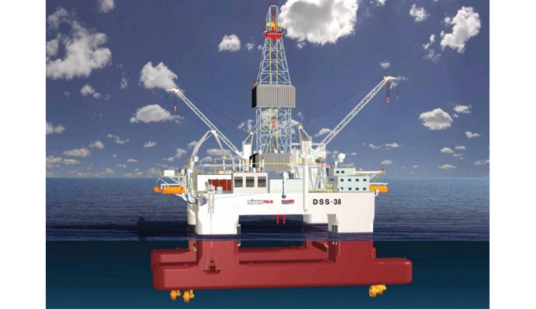
8.4.3.1: Jack-Up Rig
A jack-up rig is a floating drilling rig with (typically) three retractable legs which can be raised while the rig is moved onto location (either self-propelled or towed) and lowered into the seabed to jack-up (lift) the rig to a safe height above the water level, cantilever the rig to the desired surface location of the well, and provide a stable platform for drilling operations. Figure 8.10 shows a jack-up rig with its legs retracted being towed onto location.
When on location, the legs are lowered until they reach the seabed. Once the legs reach the seabed, further extension allows the rig itself to be raised to the desired height above the water level and preparations for drilling can be commenced. The legs on a jack-up rig can be up to 500 ft. in height. Considering a 100 ft air space between the waves and hull of the rig, this allows for water depths of approximately 400 ft for drilling operations. The rotary rig on a jack-up rig can either be a conventional kelly drive rig or a top-drive rig.
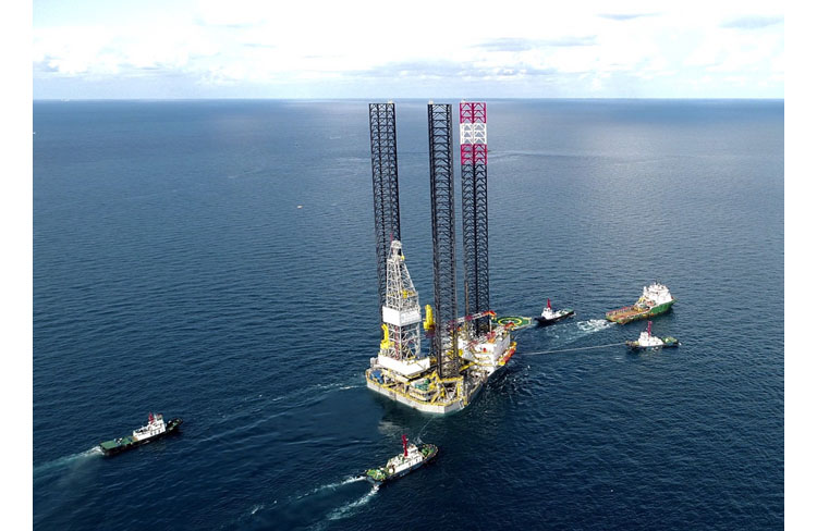
Jack-up rigs are used to drill wells in shallow waters, typically less than 400 ft of water, and can be used to drill wells to a Total Depth (TD) of 30,000–35,000 ft. Due to their mobility, jack-up rigs can be used to drill exploration wells, appraisal wells, and development wells.
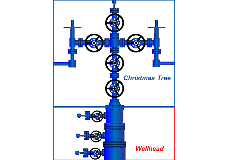
Below are three YouTube videos of jack-up rigs in action. The first YouTube video, Jackup Drilling Rig How Does It Work? (1:36), is an animation showing a jack-up rig being towed to a Well Jacket (the small structure to the right of the video). A well jacket is an offshore structure that typically contains a minimal amount of production equipment, such as, multiple trees/well heads, minimal surface production equipment (a test separator, metering equipment, etc.), and a helideck. A Tree (or Christmas Tree) is the system of valves, chokes, and gages that sits on the top of the well head and is used to direct, control, and shut-in production during the well’s productive life. An illustration of a Christmas Tree and well head is shown in Figure 8.11.
Multiple deviated wells are drilled from the well jacket to various bottom-hole targets and depths. In earlier lessons, we discussed that deviated wells are the most common well orientations used offshore. The clip you are about to watch illustrates why this is the case
Since the well jacket is already in place in this video, we know that the jack-up rig will be drilling a Development Well. This is because the oil company already knows that hydrocarbons are present below and have invested in the well jacket. Also shown in this clip is a supply boat arriving at approximately 1:12 into the video.
In the second YouTube video, Jack-up Rig (0:46), both real footage and animations are included. This video clip seems to be showing two distinct operations. In the first segment (real footage) from 0:00 to 0:12, we see an actual jack-up rig in-place next to two small offshore structures. The structure nearest to the drilling rig is a well jacket as discussed earlier. The second small structure connected by the bridge is a small production platform. These structures are referred to as Bridge-Linked Structures. Since these two structures are present, we know that the jack-up rig is drilling a Development Well.
The animation then begins at 0:12 and appears to show a rig drilling an exploration or appraisal well. We know this because there are no production facilities present in the animation. In fact, the narrator states “… if they hit oil, they will cap the well, jack the rig down, and then tow it to its next location … and a permanent drilling platform will take over pumping the oil.”
I selected this video for two reasons:
- It shows footage of an actual jack-up rig and two offshore structures
- It shows an exploration or appraisal well being drilled from the jack-up rig
I will have a little commentary on some of the narrator’s comments after you watch the video.
I did have a few issues with the narrator in this video. Now that you are an “insider,” did you catch some mistakes made by the narrator? Everything was going well until he stated “… and a permanent drilling platform will take over pumping the oil.” What he should have said was: “… and an offshore facility will take over producing the oil.” As we just learned, a platform produces the oil (this “platform” may be a simple well jacket as we have seen, a large complex Production, Drilling, and Quarters (PDQ) Platform, or a Floating Production, Storage, and Offtake (FPSO) vessel). Regardless, a “permanent drilling platform,” if they existed, would drill, it will not “pump” anything (except for fluids required in drilling, cementing, completion, or workover operations).
Second, the narrator assumed that the discovery well would need to be pumped. As we have seen in earlier lessons, not all reservoirs need artificial lift; many flow naturally. The decision to use artificial lift on this potential discovery will be up to the production engineer and the Asset Team.
The third YouTube video, Haven jack-up test (2:59), is actual footage of a jack-up rig being jacked up, either in a fabrication yard or for periodic maintenance. I selected this video because it shows actual footage of the jack-up and jack-down operations.
8.4.3.2: Semi-Submersible Rig
A Semi-Submersible Rig or a “Semi-Sub” or a “Semi” or a “Floater” is a drilling rig that is used to drill wells in water depths inaccessible to jack-up rigs (water depths greater than 400 ft). Semi-submersible rigs are buoyant and, unlike jack-up rigs which rest on the seabed, float during drilling operations. A semi-submersible rig is a drilling rig that is situated on a deck space that rests on several columns which, in turn, are attached to floating pontoons. Figure 8.12 shows a semi-submersible drilling rig.
During transport (either self-propelled or towed), the pontoons allow the vessel to float in the water until it is on location. Once on location, water is used as ballast to partially flood the pontoons and columns to allow them to sink to a position below the water level. This is done to create greater stability during drilling operations by adding mass to the vessel and providing it with a deeper draft. The columns provide additional stability to the vessel during drilling operations due to their small cross-sectional area as little wind, wave, or tidal energies are imparted to the columns and the vessel (this is called Wave Transparency). In addition, a system of Thrusters (high energy propellers) is used to control the pitch, roll, and yaw of the vessel and to provide Dynamic Positioning to keep the rig at the same surface location during drilling operations. The thrusters are the yellow devices under the pontoons in Figure 8.12. Semi-submersible drilling rigs are considered to be the most stable of the deeper water MODUs.
Semi-submersible rigs are used to drill wells in water depths up to 9,500 ft. The current world record water depth for a semi-submersible rig using dynamic positioning is 9,472 ft.[3] Due to their stability, semi-submersible rigs are also preferred in harsh offshore environments. Semi-submersible drilling rigs are capable of drilling wells to a TD (total depth) of 30,000 – 35,000 ft.
I have included a video below, Maersk Drilling - Ultra deepwater semi-submersible rig - Maersk Developer (17:48), showing an animation of a semi-submersible drilling rig. The drilling rig shown in this animation is the Maersk Developer rig, a very modern rig (Note: rigs like this one do exist – this is not a “rig-of-the-future” video.). This is a promotional video, so you may need to overlook its commercial nature. I selected this video clip because it ties together a lot of the concepts that we have discussed in this and past lessons; it shows the interior of the rig; and it discusses many of the rig specifications considered in the design (remember, you as a drilling engineer will need to coordinate with the drilling company for the proper rig specifications when contracting a rig).
In the video, the narrator discusses two concepts that we have not gone over yet, a Riser and a Moon Pool. A Riser is a piece of vertical pipe that attaches to the Tree (see Figure 8.11) and, in the case of a Subsea Tree (a tree that sits on the seabed) extends upward to the water surface. Risers act as conduits for drilling and completion fluids during drilling operations or as conduits for produced fluids during production operations.
A Moon Pool is a hole in the deck of a ship or vessel that allows for communication from the deck to the water surface. I will discuss the moon pool in more detail when we discuss Drill Ships. The rotary system of the drilling rig sits above the moon pool. It is where the drill pipe goes from the rig through the deck and into the water.
Here is the link to the video (17:48) on the “Maersk Developer,” a semi-submersible drilling rig:
[Music]
Welcome to the mask developer. The first in a series of three ultra deep water semi-submersibles delivered to Maersk drilling between 2009 and 2010. The state-of-the-art design of the rigs was made in collaboration between maersk drilling, kempelfelt, and marine structure consultants based on input from customers and service providers to oil companies.
The rigs are designed to operate in moderate met ocean conditions. In water depths of up to ten thousand feet and they are capable of drilling to a depth of thirty thousand feet. They have been designed to drill in complete deep water wells and install subsea facilities with optimum efficiency. The rigs are dynamically positioned semi-submersible with eight four megawatt thrusters and have a transit speed of seven knots. They also have eight anchor winches for use with a pre-laid mooring system.
With a displacement of fifty three thousand metric tons at drilling draft and a variable deck load of seven thousand metric tons, the rigs have large storage capacities for the operator's consumables and also provide dedicated and optimized extensive deck space and layout for the operator's equipment.
The design has been developed to deliver a safe efficient and innovative high-end drilling tool to the industry. Maersk drilling believes that the way to increase efficiency and safety is to increase the mechanization of the drilling process. Essential to this process is the selection and hiring of the correct personnel to operate the equipment. The senior crews for these rigs are involved 18 months in advance of the rig going to work in order to go through a vigorous training and familiarization process.
Let us look at this rig in more detail. The central control room, or bridge, is located on top of the accommodation block. Dynamic positioning, ballast control, and principal alarm monitoring is conducted from here. Ample office space and conference facilities on the upper deck is available for the rig crew, the clients representatives, and third-party service companies. Accommodation is provided for 180 personnel, consisting of ten single and eighty five two birth cabins. The five decks provide all the facilities you would expect of a floating hotel including 270 square meters of recreational space.
We'll now move our attention to the features for enhanced efficiency starting out with the drill floor and tubular handling systems. Within the derrick, there are two hoisting systems, the main and the auxiliary. The main line activity takes place on the right hand side and the offline activity on the left hand side. The derrick itself is rated to three million pounds combined load. The main hoisting system is outfitted with a two million pound capacity while the auxiliary is rated to one and a half million pounds. We have designed the rig to be able to achieve dual handling activities. As seen here, this means that for instance, while tripping with the main system, casing for the next step of the operation can be made up and racked back in the low setback area by the crew working with the auxiliary. Tripping drill pipe, on the main well center, requires no crew member contact with any of the moving machinery. The two vertical pipe rackers, which allow the concurrent activities, are controlled from the drillers control room by two drillers and their assistants. The senior team works the main system, which is on the right as we are now looking at the drill floor. The tubular setback area is outside the derrick and drill floor on the cellar deck, which provides a greater pipe setback capacity and a lower center of gravity. There is in excess of 50,000 feet setback capacity for drill pipe and we can rack from 16 inch casing to 7 inch liner with capacity for 15,000 feet of 7 inch liner. Here we can see the pipe being delivered from its storage area at the aft of the drill floor. It is a safe and efficient system controlled and monitored by the assistant driller by means of a cctv system while the driller is running the pipe into the well. The casing has been made up and racked on the port offside of the drill floor ready to be run in stands of three joints saving makeup time when it is to be run into the well. The two drill crews are going to be constantly active, as are the maintenance crews, who will be following Maersk drilling's preventative maintenance systems, thus ensuring the equipment is always ready to deliver high performance.
The mud system has been designed to allow mixing and handling of two fluids simultaneously. This will reduce the time taken to change from water-based mud to oil-based mud, for example. The solids control system consists of eight shell shakers split into two banks of four. We are able to install cuttings dryers and centrifuges for zero discharge operations when required and as mentioned before there is ample deck space and storage capacity for any combination of cuttings handling and disposal. We have a fluid surface capacity of 1,500 cubic meters. Amongst the largest of any semi-submersible. Four 2,200 horsepower mud pumps, rated to 7500 psi are provided for optimum hydraulics and to minimize downtime. There are storage tanks in the pontoon for weighted liquid mud, brine base oil, and fuel oil. Large capacity for bulk material is also provided in the columns for a total of 1,360 cubic meters. The eighteen and three quarter inch fifteen thousand psi BOP has two annulars and six ram preventers. The lower ram can be configured as a test ram. The unit has a multiplex control system with redundancy to allow both pods to operate with one fiber optic cable. The riser is stored vertically, forward of the drill floor, and we're able to store 9,600 feet. We see the riser handling crane delivering the 75-foot clip riser joints to the drill floor handling system where a double is being prepared to be connected to the BOP. Here we can see the riser running tool being remotely made up to the riser joint. The riser guidance arm centralizes the riser joint over the riser spider.
Here we are looking at the moon pool area. This large moon pool also gives the flexibility for multiple activities. The BOP carrier moves to well center. The riser is lowered onto and connected to the BOP. The underhull guides are used to secure the BOP before it is run into the water. Final checks are made prior to running the BOP and riser into the water.
The riser is made up with clip connectors. From stab to make up of the connector takes 12 seconds. This represents a considerable time saving in comparison to other marine riser connectors available in the market. The riser string has now been run, and the riser gas handler is now installed. This tool will allow the riser above the BOP rams to be circulated to the choke manifold and mud gas separator in the event of a weld influx reaching above the BOP. The slip joint is equipped with a remote operated pull in system that greatly enhances the safe and efficient handling of the kill and choke hoses and mud boost lines.
Work baskets installed in the moon pool area, and capable of traversing the length of the moon pool, assist with the safe operations over water significantly reducing the requirement for man-riding winch operations. The 4.2 million pound n-line riser tensioner system is secured to the riser string. This system has a two million pound trip saver feature which allows a wet parking position for the BOP and riser string if required.
The port side crane is a heave compensated crane with a capacity of 165 metric tons, when used for cargo handling. The crane is rated to 100 metric tons in a 10,000 feet water depth.
The knuckle boom crane, situated at the aft of the rig, is used to supply tubulars and equipment to the upper pipe deck and elevated catwalk area, a large number of the lifts can be accomplished without assistance from the deck crew thus greatly enhancing the safety.
The starboard crane, is a conventional deck crane, which is also able to work on the BOP when the BOP is stored on deck. It has a 165 foot boom length. A 60 ton rating at minimum radius on the main block and 15 ton rating on the whip line.
We have simulated loading the rig for typical well situations and for envisaged situations. As illustrated, we can see the rig loading up with some completion equipment.
on the port side of the rig, we can accommodate multiple subsea trees and accessories which can be easily brought on board the rig using the sub sea crane.
As this rig has been designed for multiple sub sea developments, the large staging area is matched with a large capacity in the moon pool for handling subsea trees and accessories. Sub-sea equipment can be deployed to the seabed using the main well centre and the sub-sea crane. The subsea trees and equipment are moved from the staging area into the moon pool. Equipment can then be stacked up on the tree cart. The cart has 230 metric ton capacity and large vertical clearances to handle vertical or horizontal subsea tree systems. Additional space and clearance are provided for deployment of external control systems and other circulating lines. Whilst most of the work can be carried out within the handrails, work baskets aid the safe operations in this area.
There is 17 meters of available build height from the tree carrier to the underside of the overhead crane. With the available build height and carrier capacity for tree, LRP and EDP can be stacked up and tested prior to deployment. Once the tree has been built using the bridge crane in the moon pool, it can be moved to drill center in preparation for deployment. The casing sleeve is lifted to allow this.
A number of external electrical hydraulic and or control lines may be attached to the production tubing and tubing hanger running tool or the subsurface test tree. We will use the deck above the main draw works to provide space for the full range of the related equipment.
The production riser is now attached the moon pool trolley is retracted and the subsea tree is run from the main well center.
Subsea completions involve a substantial amount of additional equipment and services including completion fluids, well test equipment, stimulation, wire line, coil tubing, downhole tubing, and accessories. The large usable deck space on the rig provides the capability to load all of these items on board. After consultation, special attention has been given to third party equipment and services. specific areas of deck have been identified for particular placement of equipment. For example, the selected location of the coil tubing unit has been deck strengthened to support the largest coil tubing unit available in the market. Modeling has been carried out to ensure that clashing is avoided when entering wire line or coil tubing to the rig floor.
The heave compensating crane allows an additional capability for deploying subsea equipment to the seabed. This unique feature will improve efficiency for multiple weld developments. Because of the complexity of subseacompletion operations, two ROVs are often used the main work class ROV is within the structure of the rig with its own moon pool. When installed a second work class ROV can be deployed from the aft end of the rig. Guided launching systems are provided for each ROV to allow deployment and recovery in high currents and heavy sea states.
[Music]
We believe that we have designed a rig to optimize deep water drilling and development activities. Thank you for allowing us the opportunity to present Maersk drilling's new ultra deep water development semi-submersibles.
[Music]
[3] PetroWiki: Semi Submersibles [26]
8.4.3.3: Drill Ships
As the name implies, a Drill Ship is a sea-going ship that is specifically modified to perform deep water drilling operations. They are equipped with an on-board drilling rig that sits above a Moon Pool (a hole in the ship’s structure from the main deck through to the hull). The Moon Pool (or “Wet Deck”) allows drill pipe to extend from the rotary system of the drilling rig, through the structure of the ship, through the hull, into the water to the sea floor, and into the wellbore. Figure 8.13 provides a picture of a drill ship.
Drill ships are used for deepwater drilling in regions with little onshore logistical support. Drill ships can typically store large quantities of supplies which allows for their use in more remote regions. Consequently, drill ships are often used for exploration well drilling in remote, deep water locations.
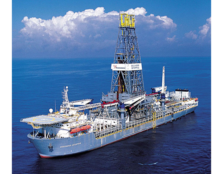
Like semi-submersible drilling rigs, drill ships are kept on location during drilling operations with the use of a system of dynamic positioning thrusters. As previously discussed, however, semi-submersible drilling rigs are considered to be a more stable drilling platform than drill ships.
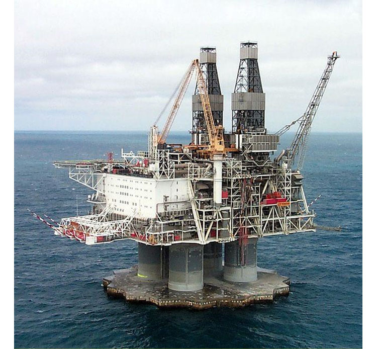
8.4.3.4: Drilling Rigs on Fixed Production Platforms
In addition to the Mobile Offshore Drilling Unit (MODU) discussed so far, offshore wells can be drilled from fixed production platforms. Figure 8.14 shows a picture of the Hibernia Platform in the Atlantic Ocean offshore of Newfoundland, Canada. As seen in this photo, the Hibernia Platform has two drilling rigs for simultaneous drilling or workover operations. In addition to these rig activities, the Hibernia Platform handles production activities such as fluid separation and processing.
8.5: Key Learnings
- There are six stages in the life cycle of a producing oil or gas field
- Exploration Stage
- Appraisal/Delineation Stage
- Development Stage
- Plateau Stage
- Decline Stage
- Abandonment Stage
During the Exploration Stage, wells are drilled with the objective of proving the existence or non-existence of oil or gas at locations deemed promising by geophysicists and exploration geologists. During the Appraisal/Delineation Stage, wells are drilled with the objective of gaining information about the reservoir. The appraisal wells and delineation wells may or may not be suspended for future use as development wells. During the Development Stage, production and injection wells are drilled as part of the original development plan designed by the engineers and geologists that make up the Asset Team for the reservoir. During the Plateau Stage, production and injection wells are drilled with the objective of keeping the surface facilities producing at 100 percent capacity. During the Decline Stage, infill production wells and pattern realignment wells are drilled to attempt to arrest the natural decline of the reservoir. Finally, during the Abandonment Stage, all wells are abandoned.
- Drilling engineers take the lead role in developing well proposals and rig schedules during all stages of the field development
- Drilling engineers take the lead role in any activity requiring a drilling rig. They are active members of any Asset Team during all phases of the life cycle of an oil or gas field. The drilling engineers reform all activities designing the well. They perform all calculations relating to the well design including: drilling fluid specifications, casing design (grades and depth), cement calculations, and drill string design
- Drilling engineers take an active role in coordinating all rig activities including: liaising with the drilling contractor, supply companies, government agencies, internal HSE (Health, Safety, and Environment Groups) and any other groups required for safe and efficient rig operations.
- Many companies and their personnel are involved in drilling oil and gas wells. These include:
- Drilling contractor company
- Operating company
- Service companies
- Cable tool rigs had their origins in the percussive drilling techniques used by ancient Chinese and Persian civilizations and are of historic importance because Colonel Edwin Drake used a cable tool rig to drill for oil in Titusville, PA in 1859. This event is considered to be the beginning of the modern oil and gas industry.
- Rotatory rigs are used almost exclusively in the oil and gas industry today. The two most common rotary drilling rigs are:
- Conventional rotary table rig
- Top-drive rig
- The conventional rotary table rig applies torque to the drill string and drill bit through a series of mechanical devices that sit on the rig floor. These are:
- Kelly
- Kelly bushing
- Master bushing
- Rotary table (or turn table)
- The rotary table is the device that is connected to the main power system of the rig (usually through a chain and gear system). The rotary table imparts the rotation (torque) to the master bushing, kelly bushing, kelly, drill string, and drill bit).
- The drill string is made up of 30-foot joints of drill pipe. These joints are connected as doubles (two joints) or triples (three joints) and racked and stored onto the side of the derrick as stands of drill pipe depending on the specifications of the rig.
- On a conventional rotary table rig, drill pipe is added to the drill string, one joint at a time. The next joint of drill pipe to be added to the drill string is temporarily stored in the mousehole on the rig floor.
- A top-drive rig applies torque to the drill string and drill bit with a motor mounted on the traveling block of the derrick.
- On a top-drive rig, a single joint, a double, or a triple of drill pipe can be added to the drill string during a connection. When multiple joints are connected, a significant reduction in the time required to connect drill pipe is achieved. This creates a more efficient drilling process.
- In this lesson, we also discussed three Mobile Offshore Drilling Units (or MODUs) used for offshore drilling:
- Jack-Up rigs
- Semi-Submersible rigs
- Drill ships
- A jack-up drilling rig is a rig with three or more (typically three) retractable legs that can be used to jack the rig up above the wave action of the water surface. Jack-up rigs are towed (or self-propelled) to the well’s surface location. Jack-up rigs can be used in water depths of up to 400 ft of water; can be used to drill wells to a Total Depth (TD) of 30,000 – 35,000 ft; and can be used to drill exploration, appraisal, delineation, or development wells.
- A semi-submersible drilling rig is a rig with multiple pontoons that are used to keep the rig floating while drilling. A semi-submersible rig uses a system of thrusters for dynamic positioning of the rig while drilling and is considered the most stable drilling rig for offshore drilling. Semi-submersible rigs can be used to drill wells in water depths up to 9,500 ft and are capable of drilling wells to a TD of 30,000 – 35,000 ft.
- A drill ship is a sea-going ship that is specifically modified to perform deep water drilling operations. Drill ships are used for deep water drilling in regions with little onshore logistical support. They can typically store large quantities of supplies which allows for their use in drilling exploration wells in more remote regions. In addition, drill ships can be used to drill appraisal, delineation, and development wells in oil or gas fields beneath deep water surface locations.
- In addition to the Mobile Offshore Drilling Units, we saw that offshore drilling can be performed off of large Production, Drilling, and Quarters Platforms.
8.6: Summary and Final Tasks
Summary
We began this lesson by discussing the life cycle of a producing field. The six stages of field development are:
- Exploration Stage
- Appraisal/Delineation Stage
- Development Stage
- Plateau Stage
- Decline Stage
- Abandonment Stage
We then discussed the role of the drilling engineer in each of these stages. The main point of this discussion was that whenever a drilling rig is involved in a field activity, a drilling engineer typically takes the primary role in developing the rig program (drilling fluid properties, cement properties, casing design, drill pipe specifications, etc.) and coordinating the rig activity with all required companies and agencies.
We then discussed the role of the drilling contract company in the oil and gas industry. We discussed two common contracts used by operating companies to obtain the services of a drilling company, its equipment (including the rig), and its personnel:
- Day-rate contract (most common contract)
- Turn key contract
We then discussed the various members of the rig crew, their roles and responsibilities, whom they report to, the company that employed them (operating company, drilling company, or service company). Later in the lesson, we saw several YouTube videos showing the rig crew personnel performing some of their duties.
We also discussed historic rigs (cable tool rigs) and modern rigs (rotary rigs). The two rotary rigs that we discussed in detail were the conventional rotary table rig and the top-drive rig. The conventional rotary rig has been the work-horse of the industry for most of the 20th century, but the top-drive rig, a relatively recent innovation, is fast becoming the industry standard.
The two major advantages of a top-drive drilling rig are:
- The ability to handle multiple joints (two or three joints) of drill pipe at one time during connecting/unconnenting operations
- The ability to rotate the drill pipe while tripping into or out of the wellbore to avoid Stuck Pipe during tripping operations
Finally, we discussed the mobile and fixed drilling in offshore environments. In particular, we discussed:
- Mobile Offshore Drilling Units (MODUs):
- Jack-up rigs
- Semi-submersible rigs
- Drill ships
- Fixed drilling centers on large Production, Drilling, and Quarters (PDQ) Platforms
Final Tasks
Complete all of the Lesson 8 tasks!
You have reached the end of Lesson 8! Double-check the to-do list on the Lesson 8 Overview page [29] to make sure you have completed all of the activities listed there before you begin Lesson 9.