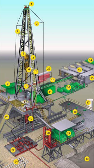
Figure 8.06 shows a schematic diagram of a typical top-drive rig. In a top-drive drilling rig, the top-drive (Item 6 in Figure 8.06) is suspended from the traveling block (Item 5 in Figure 8.06) and attached to a guide system (gear train and rail system) on the derrick. The top-drive is an electrical motor that has the ability to travel vertically up and down and to impart torque to the drill pipe. These drilling rigs began to appear in the late 1990s. Although the top-drive supplies the torque for the system, a rotary table is still used to supply stability to the drill string and as a redundant (back-up) rotary system.
The advantages of a top-drive rig are that longer sections of drill pipe can be (1) connected to the drill string when the rig crew is drilling ahead, (2) connected to the drill string when tripping into the hole, or (3) unconnected from the drill string when tripping out of the hole.
As we saw in our discussion of a Conventional Rotary Table Rigs, the next 30-foot joint of drill pipe to be added to the drill string is temporarily stored in the mousehole on the rig floor. This joint of drill pipe is added to the drill string when drilling ahead or tripping into the wellbore. Tripping is the process of running drill pipe into or out of the hole for purposes other than drilling ahead. For example, if a drill bit needs to be changed due to wear, then the entire drill string needs to be pulled from the wellbore (tripping out of the hole), the drill bit needs to be replaced, and the drill string needs to be run back into the wellbore (tripping into the hole) to resume normal drilling operations. You can imagine how much ineffective rig time (in terms of not drilling ahead) is used tripping into or out of the wellbore and making or breaking connections in the drill string–particularly if the well's TD (Total Depth) is 10,000–15,000 feet (or a shallower well has a 10,000-foot horizontal section).
| Diagram | Index |
|---|---|
 |
|
| Source: United States Department of Labor - Oil and Gas Home - Illustrated Glossary Drilling Rig Components Note: On the website linked above, you can select a name from the list or a number on the graphic to see a definition and a more detailed photo of the object. |
|
I would recommend that you go to the website and use the links to get a description of each component of the rig.
The improved efficiencies coming from a top-drive is that an entire 90-foot stand (or triple) of drill pipe can be connected to the drill string rather than a single 30-foot joint. This is because the top-drive can go to the full height of the derrick using the traveling block to connect to the entire stand of drill pipe. Note, however, that not all top-drives use a triple when connecting drill pipe; some use a Double (two joints), while others use a single joint from a mousehole.
Many of the concepts that we have been discussing are best illustrated with a series of YouTube videos and screen captures.
The Drill Training - Run drill pipe through rotary table YouTube clip (1:07) is an animation of how drill pipe connections are made on a conventional rotary rig. As I mentioned, on a conventional rotary table rig, only one joint (30 feet) of drill pipe can be added to the drill string at one time.
Highlights from this video include:
- Figure 8.07: Screen Capture at 9 seconds into the video: Rig Components
- Figure 8.08: Screen Capture at 19 seconds into the video: Use of Slips
- Figure 8.09: Screen Capture at 23 seconds into the video: Use of Mechanical Tongs
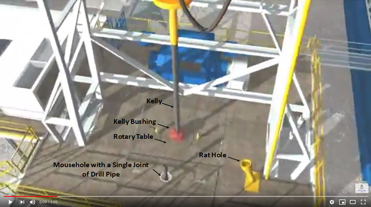
In the screen capture shown in Figure 8.07, we see many of the components discussed in this lesson: the kelly, kelly bushing, rotary table, mousehole, and rat hole. Throughout the video, you can see these components of the rig used in action.
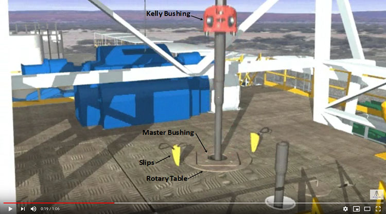
In the screen capture shown in Figure 8.08, we see the slips (yellow). As shown in the video, the slips are used to suspend the drill string when it is disconnected from the rig’s hoisting system.
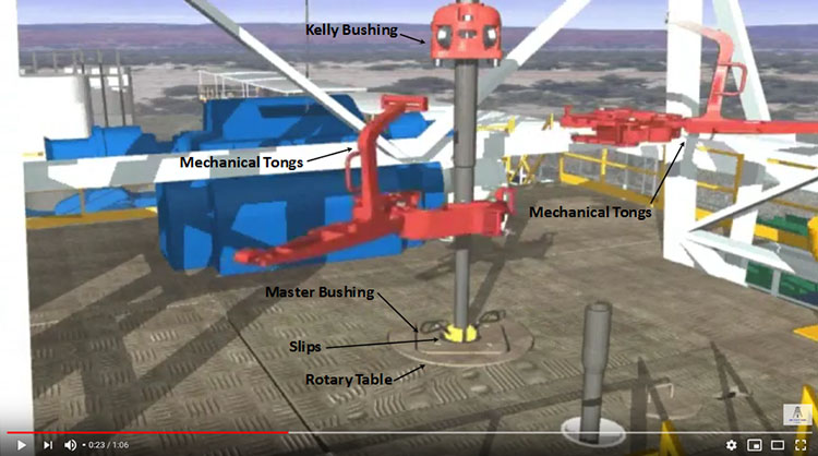
In the screen capture shown in Figure 8.09, we see the mechanical tongs (red). As shown in the video, the mechanical tongs are used to grip the kelly and drill string to aid in uncoupling (unscrewing) the two.
The A Drill Pipe Connection YouTube clip (5:42) below is of several Roughnecks (discussed earlier in this lesson) on an actual rig crew performing the same operations that you saw in the animation. Again, these tasks are being performed on a conventional rotary table drilling rig.
At several points in the video you can see a roughneck Throw Chain around the drill pipe. The Winding Chain is used to apply the torque that is used to screw or unscrew the threads in the drill pipe to couple or uncouple the joints.
What I like about this clip, and the reason that I selected it, was because of the “non-standard operating procedure” that seems to be occurring in the video. Did you spot it?
At around 2:52 into the video, it appears that while two of the roughnecks were trying to remove the slips from the master bushing, the hoist system on the derrick was attempting to assist them by lifting the kelly and drill pipe to release pressure from the slips. Instead of freeing the slips, the hoist appears to have lifted the entire section of the rig floor covering the rotary table, along with the two roughnecks. You can hear someone laughing in the video.
At around 3:31 into the video, one of the roughnecks and the hoist appear to use a piece of drill pipe to tamp the section of rig floor back into place. This piece of drill pipe is then placed into the mousehole as the next piece of drill pipe to be connected to the drill string. This is not a standard operating procedure on the rig floor. After this incident, you can see the rotary table and kelly bushing rotating in the manner discussed in these lesson notes.
In the tripping pipe with top drive YouTube clip (5:12), we will now see a rig crew performing the same operations on a top-drive rig.
In this video, you can see two roughnecks connecting Doubles (two joints) of drill pipe to the drill string as they trip into the wellbore. You can tell that they are connecting doubles by counting the joints as they go into the wellbore. You can also tell that they are tripping into the hole because as they add the new drill pipe, they just run it into the hole and do not drill.
The Making a connection on a top drive triple from the derrick YouTube clip (3:26) is of a Derrickman (discussed earlier in this lesson) making connections on a top-drive rig from the perspective of the monkey board (Item 4 in Figure 8.06).
In this video, the derrickman appears to be connecting Triples (I think that I count three joints of drill pipe looking downward to the rig floor). As I mentioned, this video is taken from the monkey board on the top of the derrick.
The improved efficiency of the top-drive rigs comes from its ability to connect longer sections of drill pipe during tripping and drilling operations. This is done in less rig time and with less cost than a conventional rig. The two major advantages of a top-drive drilling rig are:
- the ability to handle multiple joints (two or three joints) of drill pipe at one time during connecting/unconnecting operations
- the ability to rotate the drill pipe while tripping into or out of the wellbore to avoid Stuck Pipe during tripping operations
Extended Reach Drilling enables wells with long horizontal or near-horizontal lengths to be drilled through the reservoir in a more efficient manner than in the past. These long horizontal wells are one of the technology enhancements that has resulted in the “shale boom” in the U.S. domestic oil and gas industry in formations such as the low permeability Marcellus Shale in western Pennsylvania, Ohio, and West Virginia. The other technological advancement required for the shale boom was the ability to stimulate these extended reach wells with multiple hydraulic fractures (as we discussed in Lesson 7).