A Semi-Submersible Rig or a “Semi-Sub” or a “Semi” or a “Floater” is a drilling rig that is used to drill wells in water depths inaccessible to jack-up rigs (water depths greater than 400 ft). Semi-submersible rigs are buoyant and, unlike jack-up rigs which rest on the seabed, float during drilling operations. A semi-submersible rig is a drilling rig that is situated on a deck space that rests on several columns which, in turn, are attached to floating pontoons. Figure 8.12 shows a semi-submersible drilling rig.
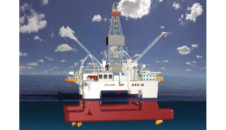
During transport (either self-propelled or towed), the pontoons allow the vessel to float in the water until it is on location. Once on location, water is used as ballast to partially flood the pontoons and columns to allow them to sink to a position below the water level. This is done to create greater stability during drilling operations by adding mass to the vessel and providing it with a deeper draft. The columns provide additional stability to the vessel during drilling operations due to their small cross-sectional area as little wind, wave, or tidal energies are imparted to the columns and the vessel (this is called Wave Transparency). In addition, a system of Thrusters (high energy propellers) is used to control the pitch, roll, and yaw of the vessel and to provide Dynamic Positioning to keep the rig at the same surface location during drilling operations. The thrusters are the yellow devices under the pontoons in Figure 8.12. Semi-submersible drilling rigs are considered to be the most stable of the deeper water MODUs.
Semi-submersible rigs are used to drill wells in water depths up to 9,500 ft. The current world record water depth for a semi-submersible rig using dynamic positioning is 9,472 ft.[3] Due to their stability, semi-submersible rigs are also preferred in harsh offshore environments. Semi-submersible drilling rigs are capable of drilling wells to a TD (total depth) of 30,000 – 35,000 ft.
I have included a video below, Maersk Drilling - Ultra deepwater semi-submersible rig - Maersk Developer (17:48), showing an animation of a semi-submersible drilling rig. The drilling rig shown in this animation is the Maersk Developer rig, a very modern rig (Note: rigs like this one do exist – this is not a “rig-of-the-future” video.). This is a promotional video, so you may need to overlook its commercial nature. I selected this video clip because it ties together a lot of the concepts that we have discussed in this and past lessons; it shows the interior of the rig; and it discusses many of the rig specifications considered in the design (remember, you as a drilling engineer will need to coordinate with the drilling company for the proper rig specifications when contracting a rig).
In the video, the narrator discusses two concepts that we have not gone over yet, a Riser and a Moon Pool. A Riser is a piece of vertical pipe that attaches to the Tree (see Figure 8.11) and, in the case of a Subsea Tree (a tree that sits on the seabed) extends upward to the water surface. Risers act as conduits for drilling and completion fluids during drilling operations or as conduits for produced fluids during production operations.
A Moon Pool is a hole in the deck of a ship or vessel that allows for communication from the deck to the water surface. I will discuss the moon pool in more detail when we discuss Drill Ships. The rotary system of the drilling rig sits above the moon pool. It is where the drill pipe goes from the rig through the deck and into the water.
Here is the link to the video (17:48) on the “Maersk Developer,” a semi-submersible drilling rig:
[Music]
Welcome to the mask developer. The first in a series of three ultra deep water semi-submersibles delivered to Maersk drilling between 2009 and 2010. The state-of-the-art design of the rigs was made in collaboration between maersk drilling, kempelfelt, and marine structure consultants based on input from customers and service providers to oil companies.
The rigs are designed to operate in moderate met ocean conditions. In water depths of up to ten thousand feet and they are capable of drilling to a depth of thirty thousand feet. They have been designed to drill in complete deep water wells and install subsea facilities with optimum efficiency. The rigs are dynamically positioned semi-submersible with eight four megawatt thrusters and have a transit speed of seven knots. They also have eight anchor winches for use with a pre-laid mooring system.
With a displacement of fifty three thousand metric tons at drilling draft and a variable deck load of seven thousand metric tons, the rigs have large storage capacities for the operator's consumables and also provide dedicated and optimized extensive deck space and layout for the operator's equipment.
The design has been developed to deliver a safe efficient and innovative high-end drilling tool to the industry. Maersk drilling believes that the way to increase efficiency and safety is to increase the mechanization of the drilling process. Essential to this process is the selection and hiring of the correct personnel to operate the equipment. The senior crews for these rigs are involved 18 months in advance of the rig going to work in order to go through a vigorous training and familiarization process.
Let us look at this rig in more detail. The central control room, or bridge, is located on top of the accommodation block. Dynamic positioning, ballast control, and principal alarm monitoring is conducted from here. Ample office space and conference facilities on the upper deck is available for the rig crew, the clients representatives, and third-party service companies. Accommodation is provided for 180 personnel, consisting of ten single and eighty five two birth cabins. The five decks provide all the facilities you would expect of a floating hotel including 270 square meters of recreational space.
We'll now move our attention to the features for enhanced efficiency starting out with the drill floor and tubular handling systems. Within the derrick, there are two hoisting systems, the main and the auxiliary. The main line activity takes place on the right hand side and the offline activity on the left hand side. The derrick itself is rated to three million pounds combined load. The main hoisting system is outfitted with a two million pound capacity while the auxiliary is rated to one and a half million pounds. We have designed the rig to be able to achieve dual handling activities. As seen here, this means that for instance, while tripping with the main system, casing for the next step of the operation can be made up and racked back in the low setback area by the crew working with the auxiliary. Tripping drill pipe, on the main well center, requires no crew member contact with any of the moving machinery. The two vertical pipe rackers, which allow the concurrent activities, are controlled from the drillers control room by two drillers and their assistants. The senior team works the main system, which is on the right as we are now looking at the drill floor. The tubular setback area is outside the derrick and drill floor on the cellar deck, which provides a greater pipe setback capacity and a lower center of gravity. There is in excess of 50,000 feet setback capacity for drill pipe and we can rack from 16 inch casing to 7 inch liner with capacity for 15,000 feet of 7 inch liner. Here we can see the pipe being delivered from its storage area at the aft of the drill floor. It is a safe and efficient system controlled and monitored by the assistant driller by means of a cctv system while the driller is running the pipe into the well. The casing has been made up and racked on the port offside of the drill floor ready to be run in stands of three joints saving makeup time when it is to be run into the well. The two drill crews are going to be constantly active, as are the maintenance crews, who will be following Maersk drilling's preventative maintenance systems, thus ensuring the equipment is always ready to deliver high performance.
The mud system has been designed to allow mixing and handling of two fluids simultaneously. This will reduce the time taken to change from water-based mud to oil-based mud, for example. The solids control system consists of eight shell shakers split into two banks of four. We are able to install cuttings dryers and centrifuges for zero discharge operations when required and as mentioned before there is ample deck space and storage capacity for any combination of cuttings handling and disposal. We have a fluid surface capacity of 1,500 cubic meters. Amongst the largest of any semi-submersible. Four 2,200 horsepower mud pumps, rated to 7500 psi are provided for optimum hydraulics and to minimize downtime. There are storage tanks in the pontoon for weighted liquid mud, brine base oil, and fuel oil. Large capacity for bulk material is also provided in the columns for a total of 1,360 cubic meters. The eighteen and three quarter inch fifteen thousand psi BOP has two annulars and six ram preventers. The lower ram can be configured as a test ram. The unit has a multiplex control system with redundancy to allow both pods to operate with one fiber optic cable. The riser is stored vertically, forward of the drill floor, and we're able to store 9,600 feet. We see the riser handling crane delivering the 75-foot clip riser joints to the drill floor handling system where a double is being prepared to be connected to the BOP. Here we can see the riser running tool being remotely made up to the riser joint. The riser guidance arm centralizes the riser joint over the riser spider.
Here we are looking at the moon pool area. This large moon pool also gives the flexibility for multiple activities. The BOP carrier moves to well center. The riser is lowered onto and connected to the BOP. The underhull guides are used to secure the BOP before it is run into the water. Final checks are made prior to running the BOP and riser into the water.
The riser is made up with clip connectors. From stab to make up of the connector takes 12 seconds. This represents a considerable time saving in comparison to other marine riser connectors available in the market. The riser string has now been run, and the riser gas handler is now installed. This tool will allow the riser above the BOP rams to be circulated to the choke manifold and mud gas separator in the event of a weld influx reaching above the BOP. The slip joint is equipped with a remote operated pull in system that greatly enhances the safe and efficient handling of the kill and choke hoses and mud boost lines.
Work baskets installed in the moon pool area, and capable of traversing the length of the moon pool, assist with the safe operations over water significantly reducing the requirement for man-riding winch operations. The 4.2 million pound n-line riser tensioner system is secured to the riser string. This system has a two million pound trip saver feature which allows a wet parking position for the BOP and riser string if required.
The port side crane is a heave compensated crane with a capacity of 165 metric tons, when used for cargo handling. The crane is rated to 100 metric tons in a 10,000 feet water depth.
The knuckle boom crane, situated at the aft of the rig, is used to supply tubulars and equipment to the upper pipe deck and elevated catwalk area, a large number of the lifts can be accomplished without assistance from the deck crew thus greatly enhancing the safety.
The starboard crane, is a conventional deck crane, which is also able to work on the BOP when the BOP is stored on deck. It has a 165 foot boom length. A 60 ton rating at minimum radius on the main block and 15 ton rating on the whip line.
We have simulated loading the rig for typical well situations and for envisaged situations. As illustrated, we can see the rig loading up with some completion equipment.
on the port side of the rig, we can accommodate multiple subsea trees and accessories which can be easily brought on board the rig using the sub sea crane.
As this rig has been designed for multiple sub sea developments, the large staging area is matched with a large capacity in the moon pool for handling subsea trees and accessories. Sub-sea equipment can be deployed to the seabed using the main well centre and the sub-sea crane. The subsea trees and equipment are moved from the staging area into the moon pool. Equipment can then be stacked up on the tree cart. The cart has 230 metric ton capacity and large vertical clearances to handle vertical or horizontal subsea tree systems. Additional space and clearance are provided for deployment of external control systems and other circulating lines. Whilst most of the work can be carried out within the handrails, work baskets aid the safe operations in this area.
There is 17 meters of available build height from the tree carrier to the underside of the overhead crane. With the available build height and carrier capacity for tree, LRP and EDP can be stacked up and tested prior to deployment. Once the tree has been built using the bridge crane in the moon pool, it can be moved to drill center in preparation for deployment. The casing sleeve is lifted to allow this.
A number of external electrical hydraulic and or control lines may be attached to the production tubing and tubing hanger running tool or the subsurface test tree. We will use the deck above the main draw works to provide space for the full range of the related equipment.
The production riser is now attached the moon pool trolley is retracted and the subsea tree is run from the main well center.
Subsea completions involve a substantial amount of additional equipment and services including completion fluids, well test equipment, stimulation, wire line, coil tubing, downhole tubing, and accessories. The large usable deck space on the rig provides the capability to load all of these items on board. After consultation, special attention has been given to third party equipment and services. specific areas of deck have been identified for particular placement of equipment. For example, the selected location of the coil tubing unit has been deck strengthened to support the largest coil tubing unit available in the market. Modeling has been carried out to ensure that clashing is avoided when entering wire line or coil tubing to the rig floor.
The heave compensating crane allows an additional capability for deploying subsea equipment to the seabed. This unique feature will improve efficiency for multiple weld developments. Because of the complexity of subseacompletion operations, two ROVs are often used the main work class ROV is within the structure of the rig with its own moon pool. When installed a second work class ROV can be deployed from the aft end of the rig. Guided launching systems are provided for each ROV to allow deployment and recovery in high currents and heavy sea states.
[Music]
We believe that we have designed a rig to optimize deep water drilling and development activities. Thank you for allowing us the opportunity to present Maersk drilling's new ultra deep water development semi-submersibles.
[Music]
[3] PetroWiki: Semi Submersibles