
2.4 Concentration with a Parabolic Reflector
Parabolic geometry is the basis for such concentrating solar power (CSP) technologies as troughs or dishes. Parabolic trough is also considered one of the most mature and most commercially proven technologies in the utility scale CSP facilities (Mendelsohn et al., 2012), so we will look at the physical principles of parabolic concentrators in some more detail.
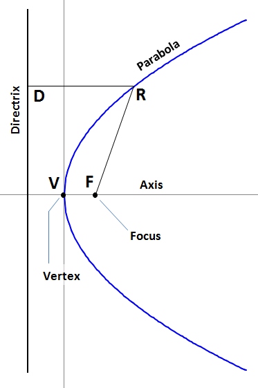
Geometrically, a parabola is a locus of points that lie on equal distance from a line (directrix) and a point (focus) - see Figure 2.6. For each point of the parabola, DR = FR. The distance VF between the vertex and focus of the parabola is the focal distance (f). The line perpendicular to the directrix that passes through the focus is the axis of the parabola; the axis divides the parabola into two parts that are symmetrical.
With origin at its vertex, and the axis of the parabola taken as x-axis, a parabola is described by the equation:
| (2.5) |
where f is the focal length.
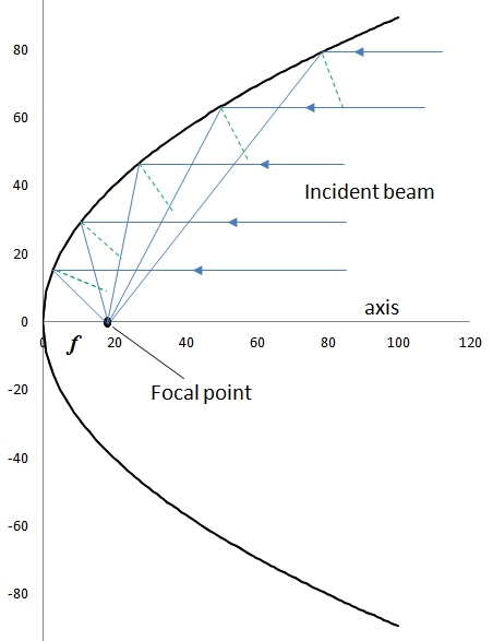
By definition of the focal point of the parabola, all incoming rays parallel to the axis of the parabola are reflected through the focus. This provides an opportunity for light concentration by using parabolic surfaces. If we assume that solar light arrives to the surface as essentially parallel rays, and apply the Snell's law (the angle of reflection equals the angle of incidence), we can assign the focal point as an ideal location for the receiver (Figure 2.7).
Solar applications deal with a parabola of a finite height (Figure 2.8). The design of the parabolic reflector takes into account the available aperture size (a), focus location (f - i.e., where receiver would be placed), and height of the reflector (h). These parameters are interrelated via the equation (Stine and Harrigan, 1986):
| (2.6) |
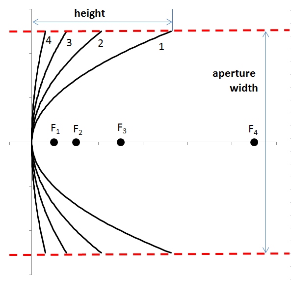
This figure above shows that the flatter the reflecting surface, the longer the focal length. The "flatness" of the shape of a finite parabola is typically characterized by the rim angle ( ). When rim angle increases (within the same aperture), the parabola becomes more curved, and the focal distance shortens.
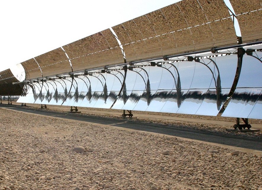
Parabolic trough (Figure 2.9) is a typical example of an imaging concentrator that utilizes the geometric relationships discussed above. Parabolic trough is one of the most widely implemented technologies for sunlight concentration at the utility scale. This type of collectors relies on sun tracking to ensure that the beam radiation is directed parallel to the parabolic axis.
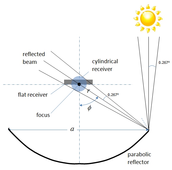
A parabolic mirror produces an image of the sun on the surface of the receiver, so the receiver size needs to be matched to the image size. Consider Figure 2.10, which illustrates this idea. Since the sun is not really a point source, solar beam incident on the reflector is represented as a cone with an angular width 0.53o (so the half-angle between the cone axis and its side is 0.267o). Being reflected at a point on the parabolic surface, the beam hits the focal plane, where it produces an image of a certain dimension, centered around the focal point. The diameter of the cylindrical receiver (D), which would intercept the entire reflected image can be theoretically calculated using aperture width (a), and rim angle ( ) as follows (Duffie and Beckman, 2013):
| (2.7) |
For the linear receiver, the width of the image (W) produced on the focal plane can be determined as follows:
| (2.8) |
The equations presented here can be used to estimate the size of the reflected light image on the receiver for different shapes of parabolic reflectors. The formulas include a as a chosen aperture of the reflector (width of the trough), and ( ) as a measure of parabolic curvature. Note that these are the minimal theoretical dimensions of the reflected image that would be produced by the ideal parabolic mirror that is perfectly aligned. If there are any flaws in the mirror surface or trueness of the angle, additional spreading of the image may occur. If you are interested in more explanation of how these formulas were derived, please refer to Duffie and Beckman, 2013 book (Section 7.9)
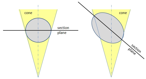
The above-described geometrical concepts apply to the cross-section of a parabolic reflector. In reality, the reflector itself is a three-dimensional shape, i.e., a parabolic cylinder with a finite length (l). So, the cone-shaped ray reflected at a point on the surface of a parabolic reflector will produce an ellipse-shaped image on the focal plane. We can see that as the reflection point is moved away from the vertex towards the rim, the ellipse transforms from a circular to a more and more elongated shape (because the cone would be sectioned by the focal plane at greater and greater angle - Figure 2.11).
Knowing the angular width of the cone, the dimensions of the ellipse image can be theoretically derived and presented as a function of (angle of deviation from the parabola axis). Below are the equations describing the length of the minor and major axes of the ellipse.
| (2.9) |
| (2.10) |
where r is the distance between the focus and reflection point (local radius) on the parabolic mirror (r=f at the vertex); is the angle between the parabola axis and the ray, and 0.267o is the half-angle of the ray cone width.
The superposition of these individual ellipses produced by each element of the reflector form the total image, which is not uniform, but rather has a distribution of light intensity. The focal length (which is related to the rim angle of the reflector) is responsible for image size, while the aperture is responsible for the total amount of energy concentrated by a collector. So, the total image intensity (brightness) at the receiver should be a function of a/f. The image brightness essentially reflects the energy flux concentration:
Energy flux concentration ~ a/f
The larger the aperture, the more energy is concentrated within a certain image size. The smaller the focal length, the smaller the image size within which the energy is concentrated.
The distribution of intensity of the energy flux within the concentrated image may have a profile similar to Figure 2.5. Different models have been applied to quantify that profile. For example, one of the approaches is called nonuniform solar disk, which suggests that the sunlight intensity coming out of the center of the solar disk is higher than that coming from its edges [Evans, 1977]. Without going into too much detail of this model, we can use the diagrams presented in the book by Duffie and Beckman (2013), which allow connecting various parameters of a parabolic concentrator with the local intensity on the receiver.
Please refer to the following reading to study the tools for image analysis via the nonuniform solar disk model, and be sure to study the example presented therein, which is very helpful.
Reading Assignment
Book chapter: Duffie, J.A. Beckman, W., Solar Engineering of Thermal Processes, Chapter 7: Sections 7.9 and 7.10. pp. 351-358.
The main goal for this assignment is to understand how to estimate concentrated image parameters using model diagrams 7.10.1, 7.10.2, and 7.10.3.
Please answer the following quick questions to check your understanding of some of the basic points in this section. The parabola cheatsheet presents a useful summary for your notes.