
6.1. Main components of large PV systems
The electric power generated by PV modules goes through a series of transformations before it reaches the grid. Those transformations specifically include adjustments of current and voltage, DC-AC conversion, and also distribution of power between storage and transmission paths. Cumulatively, we can call these operations power conditioning.
Power conditioning is an important function of any utility-scale solar plant, which ensures that the energy generated can be effectively and safely delivered to consumers. To accomplish the proper power conditioning, we need a number of specialized components (in addition to the PV modules), and we are going to take a closer look at some of those components and their operation principles in this lesson.
Photovoltaic plants contain a large amount of supporting equipment, which serves to balance the system and to make it sustainably operational. The extra components include inverters, controllers, transformers, wiring, connector boxes, switches, monitoring devices, charge regulators, energy storage devices - all of which help prepare electric power for utilization. PV systems are typically modular in design, so that additional sections can be added to the plant or removed for repairs without significant disruption of its infrastructure. The energy flow at the solar plant runs through a variety of devices, which are connected by wire network and related hardware. This supporting infrastructure is often referred to as balance of system (BOS). The quality of the BOS is very important for providing lasting and efficient operation. The industry goal is to provide PV systems with an operational lifetime of at least 25 years. [Foster et al., 2010].
The general line-up of the key components of the BOS is illustrated in the generic system scheme below.
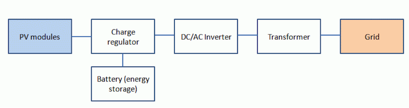
Let us briefly discuss the main components in this scheme and describe their functions.
Charge controllers or regulators manage the flow of electricity between the solar modules (arrays), energy storage, and loads. The appropriate charge control algorithm and charging currents need to be matched for the batteries (or other energy storage devices) used in the system. The main purposes of a charge controller is to protect batteries from damage and to prevent overcharging or excessive discharging. Typically, these devices operate in the switch on / switch off mode. For example, when the terminal voltages supplied from a PV system to the battery increases above a certain threshold value (Vmaxoff), the switch disconnects the PV array. The array is connected again when the terminal voltage drops below a certain value (Vmaxon). This hysteresis cycle protects the battery from overcharging. Similarly, charge controllers help prevent battery excessive discharging. When the current of the load connected to the battery is higher than the current delivered by the PV array, the load is disconnected as the terminal voltage falls below Vminoff and is connected again when the terminal voltage increases above a certain threshold Vminon. Charge controllers also participate in voltage conversion and maximum power tracking [Kalogirou, 2009].
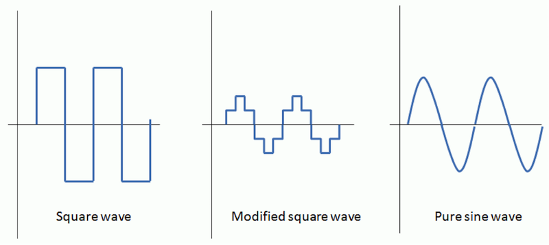
Inverters - devices that convert DC power coming from the solar modules to AC power (necessary for grid) are critical components of any PV systems. Inverters convert DC power from the batteries or solar modules into 60 or 50 Hz AC power. As with all power system components, the use of inverters results in energy losses due to interferences. Typical efficiency of an inverter well matched to the array is around 90%. Inverters are key components in both grid-connected and distributed power applications, and usually are a significant part of system cost. The AC current produced by inverters can have square, modified sine, and pure sine wave output (Figure 6.2). The pure sine is high cost and has the best power quality. The modified sine is medium cost, but has less efficiency. The square wave is low cost and lowest efficiency, which is only used by some applications. Square wave signals can be harmful to certain electronics due to high-voltage harmonic distortion. Inverters are common sources of electromagnetic noise, which can interfere with sound and video equipment. So, the inverters boxes must be grounded according to the code requirement and safety reasons [Foster et al., 2010].
Grid-tied inverters are used to tie the PV system to the utility grid. They convert DC power to AC power in synchronization with the grid. For example, if grid fails for any reason, the inverter will shut down as well. The main considerations related to PV-grid interconnection include safety, power quality, and anti-islanding. Islanding is the condition when in case of power grid going down, inverter attempts to power the grid and can result in equipment damage and safety risks to technical personnel. Grid power line with PV modules connected to it is a typical islanding situation. After the grid is down, the PV panels still continue to power the line as long as the solar radiation is present. Thus, we have an "island" of powered line within un-powered grid. Most AC grid-ties inverters have anti-islanding feature, so the inverter will reduce power to zero within 2 seconds of the grid shut-down.
Inverters are rated by the total power capacity (from hundreds to a million watts). Some inverters have a good surge capacity for starting motors, but others may have limited surge capacity. So, designers should specify both type and size of the load to be connected to the inverter [Kalogirou, 2009].
DC-DC converters or transformers are used to step up (boost) or step down (buck) voltage of DC current. Therefore, the voltage of the solar array can be chosen independently of the voltage of the load. This kind of convenience comes with a cost - DC-DC converter always have losses, although the good models have efficiency as high as 95%, with some waste heat generated [Mertens and Hanser, 2013]. Ideally (if there were no losses):
\[{P_1} = {V_1} \times {I_1} = {V_2} \times {I_2} = {P_2}\]
Where V1 and I1 are voltage and current at the input (from solar module) and V2 and I2 are voltage and current at the output, respectively.
Batteries are used in many types of PV systems to supply power at low sun conditions (night or low irradiance). Additionally, batteries are required in solar systems because of the fluctuating nature of the PV output. The battery size/capacity is selected according to the load. They are usually connected in parallel to match higher capacity. There are several types of batteries commercially available for solar applications, including lead-acid, nickel-cadmium, nickel hydride, and lithium-ion. The main requirement for the batteries that are used as energy storage for solar systems is that they must be able to go through deep charging and discharging cycles without too much degradation. Batteries are classified by the nominal capacity (qmax), which is the maximum number of ampere-hours that can be extracted from the battery under certain standard conditions.
The efficiency of a battery can be defined as the ratio of the charge extracted during discharge to the amount of charge needed to restore that state of charge. The efficiency depends on State of Charge (SOC), which is the ratio between the present capacity of the battery and the nominal capacity (SOC = q/qmax). For example, SOC=1 when the battery is fully charged, and SOC=0 when the battery is fully discharged. The battery lifetime is often presented as the number of charge-discharge cycles the battery can sustain before losing 20% of its nominal capacity [Kalogirou, 2009].
Batteries used in power generating solar systems are actually different from car batteries. The car batteries are not designed to withstand the deep charge-discharge cycles and therefore should not be used with solar power generation. Batteries are usually installed in well-ventilated locations - (e.g., utility rooms) to minimize hazards from spills and made them available for easy maintenance or replacement. More details of energy storage technology will be covered in Lesson 9.
Grounding and bonding of related DC and AC circuits is important to maintain system integrity. According to the U.S. electric code, the systems operating under 50 V are not required to be grounded, although chassis grounding is required for all hardware.