
6.8. PV--Grid connection
Interconnections in solar systems and their connection to the public grid are regulated by National Electrical Code®(NEC). The NEC is a nationally recognized standard for safe electrical installation and is routinely applied all over the U.S. It is intended for use by trained personnel and is applied to integration of all wiring, overcurrent protection, disconnects, grounding, and equipment regulations. Article 690 of NEC is specifically dedicated to solar photovoltaic systems, and article 490 is applied to large utility-scale systems (over 600 V). Importantly, the NEC addresses the circuit requirements for solar systems, such as maximum current and voltage.
Maximum Voltage Rating
The first condition for determining the maximum DC voltage is that it should be lower than the voltage limits defined for any component on the DC side of the system. The maximum DC voltage output (Vmax) from a PV system can be estimated using the following formula (Dunlop, 2010):
where Voc is the open circuit voltage of a module at 25 oC, nser is the number of modules connected in series, and CT is the temperature correction factor. The CT factors account for the voltage increase with decreasing temperature and can be found in Table 690.7 in Article 690—Solar Photovoltaic (PV) Systems of NEC.
For Example
What would be the total maximum output voltage of the system including 20 modules connected in series, each module having open circuit voltage of 18 V, if the minimum expected temperature at the locale is -25 oC?
Applying the formula (11.1): Vmax = 18 V × 20 × 1.20 = 432 V
Maximum Current Rating
Per NEC code Article 690.8, which deals with circuit sizing and rating, there are two different PV circuits distinguished:
(1) PV source circuits - conductors between PV modules and to the common point of connection, i.e., junction box
and
(2) PV output circuits - conductors between the junction box and the inverter or DC loads
These two types of circuits are schematically shown in Figure 11.7. The PV source circuits and PV output circuits are rated differently with respect to the maximum current.
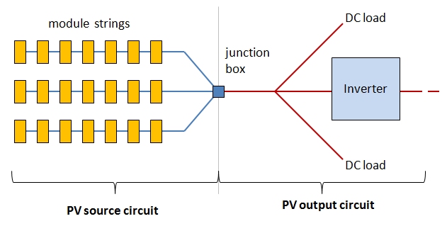
The maximum DC current rating for PV source circuits is considered at 125% of the sum of all short-circuit currents rating of all modules. This assumption is based on the fact that under enhanced irradiance conditions, modules can occasionally generate currents higher than nominal Isc values. The maximum source current is determined for each single string.
For example:
If the module short circuit current Isc = 4.8 A, then
Imax(source) = 4.8 × 1.25 = 6 A
The maximum DC current rating for PV output circuit needs to take into account all parallel strings, and in this case the source maximum current needs to be multiplied by the number of strings (npar) involved in the system.
For example:
If we have three parallel strings of modules (like shown in Figure 11.7), each with source maximum current of 6 A, then
Imax(output) = Imax(source) × npar = 6 A × 3 = 18 A
In summary, the cables within each string should be able to withstand currents of 6 A, but the cables on the inverter side should be ready for 18 A.
The estimates of the system maximum voltage and currents are key factors for choosing the inverters, determining wiring, conductor size, and required overcurrent protection.
Interconnection types
By the type of interconnections, there are several inverter types employed at different PV systems. They include stand-alone, interactive, and bimodal inverters.
The stand-alone mode does not involve grid connection, but rather uses the battery storage to collect the power from PV and convert it to AC for specific applications (Figure 11.8a). If the battery storage is depleted, the system becomes stressed.
The interactive mode does not use any energy storage, and the inverter serves as the interface between the PV and the utility grid (Figure 11.8b). In this case, power can flow in both directions. If the on-site power demand is higher than the amount supplied from the PV, the system can draw power from the grid. If the produced power is greater than the on-site power demand, the excess power is fed to the grid.
Finally, the bimodal connection (Figure 11.8c) combines both stand-alone and interactive options. Here, the energy storage provides backup for critical loads, while the excess power is fed to the grid, like in the interactive mode. If for any reason the grid loses power, this bimodal system uses a separate dedicated distribution panel to support the critical loads (such as computers, lighting, water pumping, etc.) (Dunlop, 2010).
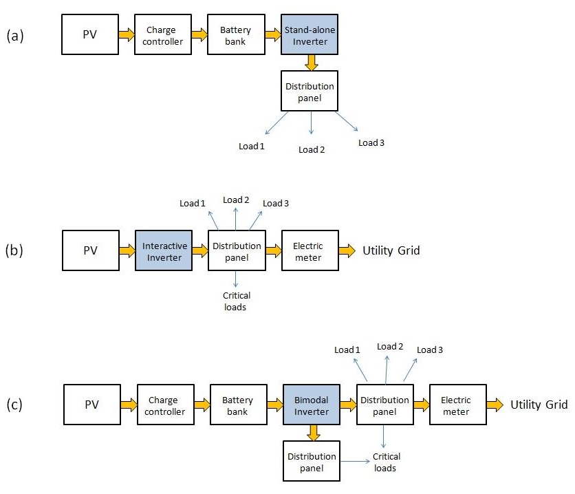
A. PV to charge controller to battery bank to stand-alone inverter to distribution panel (to load 1,2,3)
B. PV to interactive inverter to distribution panel (to load 1,2,3 & critical) to electric meter to utility grid
C. PV to charge controller to battery band to bimodal inverter (to distribution panel to critical load) to distribution panel (to load 1,2,3 & critical) to electric meter to utility grid
Please refer to the following reading to gain more insight in inverter operation in grid-connected systems.
Reading Assignment
Book chapter: Mertens, K and Hanser K.F., Photovoltaics: Fundamentals, Technology and Practice, Chapter 7, Section 7.2 Grid Connected Systems, pp. 168-177. (See E-Reserves via the Library Resources tab.)
Grid-connection challenges
The following are some known concerns arising from interconnection of different scale PV systems to the utility grid.
- Islanding is the condition when the solar power facility keeps supplying power to the grid during grid outage. This is a serious safety hazard, since utility workers who repair the grid may be exposed to unexpected voltage present in the utility line. To prevent damage to personnel and equipment, all grid-bound inverters must be able to detect outages and block power transfer. Inverters with such capability are referred to as anti-islanding inverters. Bimodal inverters may remain in stand-alone mode of operation while being disconnected from the utility grid line.
-
Power quality is reflected in the several electrical performance parameters, such as voltage, frequency, harmonic distortion, noise, etc. Many loads and equipment connected to the grid are designed to operate at certain prescribed conditions and may not be able to withstand voltage fluctuations and other disturbances. Low-quality inverters can cause poor power quality, which can cause damage to the sensitive equipment, or create hotspots in transformers.
-
Phase disbalance can occur if single-phase inverters are connected to three-phase power systems. Solution to the mismatch may be connection of three small inverters, each to a different phase, or employing a single three-phase inverter.
Please answer the following self-check questions before proceeding to the next section.
Check your understanding
Question 6. Will the PV cell voltage be higher or lower if the outdoor temperature drops to -10 oC? Find the temperature correction factor for this case.
Question 7. If a PV cell outputs 20 V at 25oC, what voltage can we expect from it at -10oC?
Question 8. Which of the following is usually true with grid-connected solar plants?.
Additional Reading on Inverters
Dunlop, J.P., Photovoltaic Systems, 2nd Ed., Chapter 8: Inverters. American Technical Publishers, 2010.
King, D.L., Gonzalez, S., Galbraith, G.M., and Boyson, W.E., Performance Model for Grid-Connected Photovoltaic Inverters, Sandia Report SAND2007-5036, 2007.