5.1.1a: Drills, Explosives Loaders, and Rippers
Drills
Drills are used to create a hole of a certain diameter and depth. Occasionally, the goal of drilling is to create an empty hole, but more often, the purpose of the hole is to accept explosives. The major components of a drill include the bit, which fragments the rock; a power source that transfers energy to the bit; and lengths of drill steel, sometimes called the drill string, that connect the bit to the drill rig proper. Drills vary by: the method of rock penetration, e.g., rotary or percussion; the location of the power source, which can be at the top of the drill string, e.g., top hammer, or at the bit, e.g., down-the-hole; primary method of powering the drill, e.g., diesel engine, electric motor, or compressed-air; and the method of mounting the drill rig, e.g., track-mounted or tire mounted.
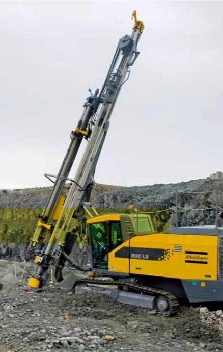
Here, we have a track-mounted down-the-hole drill with an articulating boom to facilitate drilling holes at precise angles.
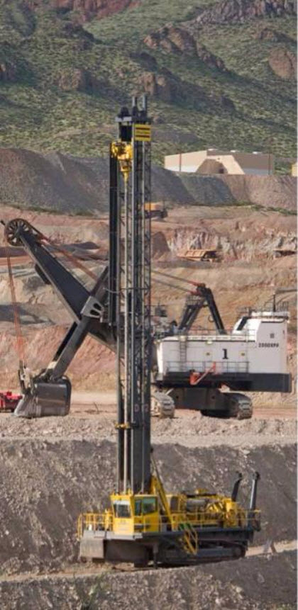
While the previous drill employs a down-the-hole hammer to apply energy to the bit, this one is a top-hammer drill, i.e., the energy source for the bit, at the top of the drill string. That means the “pounding and rotational” action has to be transmitted through the drill string to the bit. The biggest disadvantage of this approach is the loss in accuracy. The drill string tends to travel in a large helical track with the top hammer, and this causes the drill bit to “wander” off the desired location of the hole.
If these drills are going to be used underground where the headroom is limited, the mast is not as high but otherwise the drill is similar. While the accuracy of hole location is most always important, in some underground applications, it is crucial. In those, a down-the-hole hammer will be used.
Vertical or inclined holes are commonly required in surface mining, and sometimes in underground mining. It is very likely that horizontal or nearly horizontal holes will be required in underground mining, as well as overhead vertical or overhead angled holes.
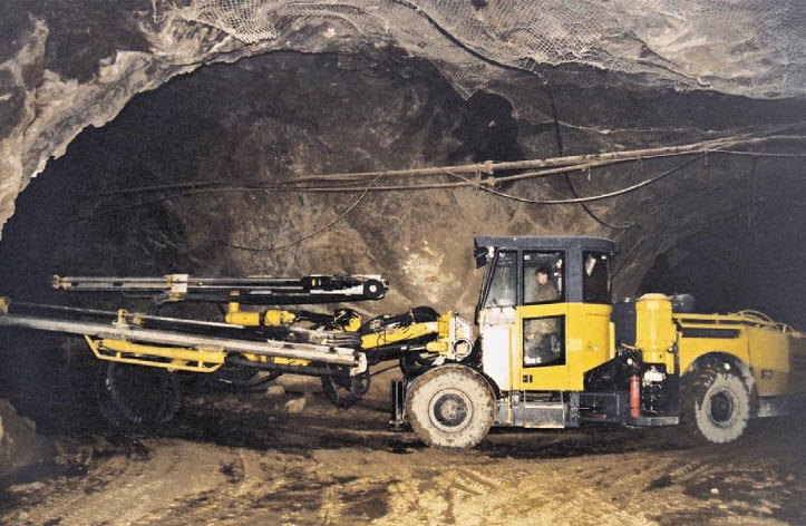
The dual boom jumbo drill is designed to drill horizontal or inclined holes at angle off of the horizontal. The depth of these holes is typically limited by the application and is on the order of 15’.
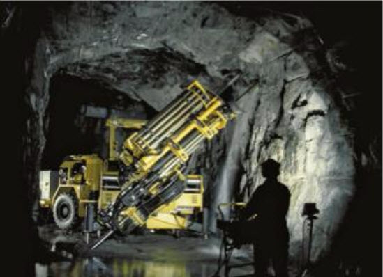
Ring or fan drilling and longhole drilling are characteristic of a few underground metal mining methods. The holes may be 150’ or long, and must be drilled to precise depths at the exact design angles. Drills to accommodate these requirements employ computer control to achieve the required accuracy, as do more and more jumbo and other drills being used in production operation. A typical drill is shown here. Note the remote operating station for the drill operator.
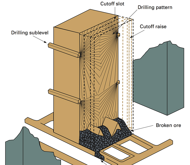
This diagram illustrates the drilling pattern required in a sublevel stoping mine. Notice the layout of the holes. What do you think would happen if a hole was started, but the angle was off by a few degrees? Or what if a particular hole were drilled to 128’ instead of the designed length of 135’? Intuitively, I am sure you can imagine that it will affect the performance of the blasting, and you are correct. We’ll talk more about this when we cover blasting, but for now, please recognize that productivity, cost, and safety are adversely affected by less-than-optimal drilling practices.
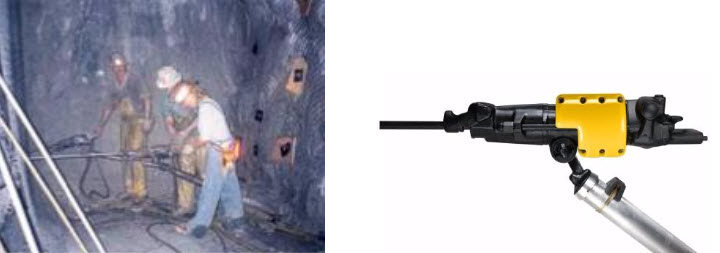
Finally, we should close our overview of drills with the handheld “jackleg” drill. In years past, these were used instead of jumbo drills in hardrock mining and for ground control applications in coal and metal/nonmetal mines. The size hole depended on the cylinder bore of the drill, as they were powered by compressed air, as well as the size of the drill bit. Hole sizes ranged from approximately 1” to 4”. Depending on the size, and consequently what the drill was used for, they were given names such as drifters or stopers. They are only used in modern mines for very specialized functions, requiring a few holes on occasion, here or there. Unfortunately, you will find them in widespread use in the underground mines of lesser-developed countries. I say unfortunately because they are brutal to use. Although much of the weight, around 75 lbs., is supported on the jackleg, the miner has to apply the thrust, i.e., pushing the drill bit into the hole. That alone is hard work. They are very loud, there is bone-jarring vibration, and they can produce dust-laden air and that along with the oil mist from the compressed air creates a respiratory hazard. Teams of miners would stand all shift-long operating these drills. Often they were paid based on the production that they achieved, and 15 years ago in the western U.S., one of these miners could easily earn $60-80 thousand dollars per year… but they earned every penny of that!
The practice of loading sticks of dynamite has all but disappeared from modern mining. Safer and more economic practices utilize explosives that are pumped, gravity-fed, or pneumatically blown into the hole. That’s not to say that we never use packaged material, because we do, and we’ll look at that when we discuss explosives and blasting practice. The vast majority of blasting, however, is accomplished with powders, gels, or emulsions that are bulk loaded.
Explosives Loaders
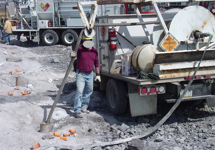
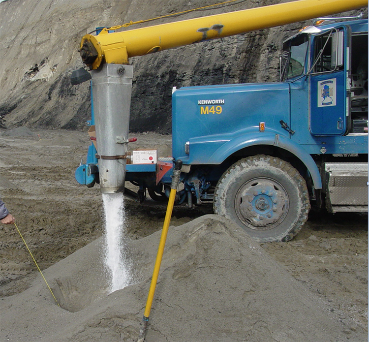
The truck below is used in surface mining. It carries the materials to mix the explosive at the hole, and the equipment to place the explosive into the hole. Such an arrangement can be found in some underground mines as well. In this example, the explosive is being pumped into the hole.
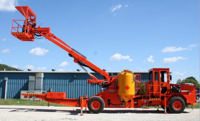
In a mine in which the height of the active mining face is on the order of 15’ to 60’ feet, you will see equipment like this. The boom allows the blaster, standing in the basket, to reach each hole, insert a hose into the hole, and then load the explosive. In this picture, you can see the yellow tank that contains the blasting agent. There is a second tank on the other side, which is obscured from view in this photo. These tanks are known colloquially as “powder monkeys.”
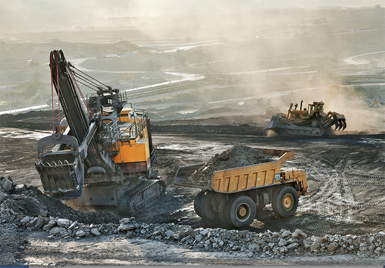
Rippers
Rippers are dozers that have been equipped with one or more large drag bits. These are pulled through the ore as the dozer moves forward. Typically, they break up the top 6” – 18”, depending on the mechanical properties of the ore. Rippers are not very common because they are suited to few deposits. Occasionally, I’ve seen them used in soft high calcium limestone and in coal, but there are other examples. In the picture here, this ripper (seen at the back of the image) has three large drag bits.