5.2.2: Active and Passive Ground Support
Ground support can be active or passive. If we take actions that actually increase the strength of the rock, then we are providing active support. On the other hand, if we do nothing to increase the strength, but instead we take an action to prevent the rock mass from falling, then we are providing passive support. There are valid applications of both categories of support. Let’s look at an example. Actually, this is a really important example!
The rock strata overlying a tabular deposit are often somewhat weak. They may consist of relatively thin layers of a weak rock. These layers, which may be a few inches to a few feet in thickness, may also have partings between them. These partings may be very thin, and very weak. Now, what is going to happen when we remove the ore from underneath the overlying rock mass that I just described?
Did you ever have a long bookshelf made of wood – wood that is not very thick? What happened when you place a full load of books on the shelf? It begins to sag in the middle, right? It may not have happened immediately, but over time, it sags in the middle. A similar mechanism is at play in the mine strata of our example. All of the weight of the overlying rock layers is pushing down. You removed the ore from underneath the strata, so you now have a long unsupported span of relatively weak rock layers. The rock layers begin to sag, and before long the lowest layer will separate from the others, and fail. When it fails, it will break apart and fall to the ground. Now, the layer immediately above the one that just failed will sag, and it too will fail. This will continue until the rock mass reaches some equilibrium. This is an unacceptable outcome! We’ll never make any money at this mining business if we can’t support the openings that we create! So, you must prevent the initial failure. What are your options?
As with the bookshelf, you could place a support in the middle of the span to support the load and prevent sagging. In our mine, we could set a timber post into place, and it would prevent the failure. This is an example of a passive support. Placing timber posts, steel arches, and so on is a time-honored means of supporting the rock and preventing failures. There are some drawbacks, however. If we’re mining a 6’ thick coal seam, we can set a 6’ post. What if we are mining a 60’ seam of limestone? Finding, handling, and placing a 60’post would be a supremely daunting task, and clearly not practical! Even when it would be easy to set a post, there can be unacceptable drawbacks to the practice.
Let’s think about a basketball arena like Bryce Jordan Center. The roof of that building spans a large area, and that roof needs to be supported. Assuming that we can obtain timber posts of sufficient length, why not set them across the width of the building, perhaps every 20’ or so to support the roof? For starters, it would make for an interesting new twist to the game of basketball as the players dodged the posts on their way to the basket! Again, not very practical, and that is the drawback in the mine as well. Instead of basketball players, we have large equipment moving around and between the working areas. Thus, in many locations, this kind of passive support is inconsistent with production needs. While passive support is an appropriate control strategy in many instances, we need an alternative for when it is not.
Roof Bolts
One of the most prevalent and effective means of providing ground support is an active support known as a roof or rock bolt. Remember the failure in the layered strata of our example mine? What if we were to clamp several of those weak layers together, forming a “laminated beam”? Beams are very strong, and, indeed, by clamping these layers together, we have strengthened the rock mass, and it will be able to support the weight on it without failing. Many of you may have seen laminated beams used in building construction. Several layers of thin and relatively weak plywood are glued together, and the result is beam with superior properties to a solid piece of wood of the same thickness.
In our case, we can’t access both sides of the rock mass to clamp the layers together, as is the case when they fabricate laminated wooden beams. Instead, we use a rock bolt, as illustrated in this diagram.
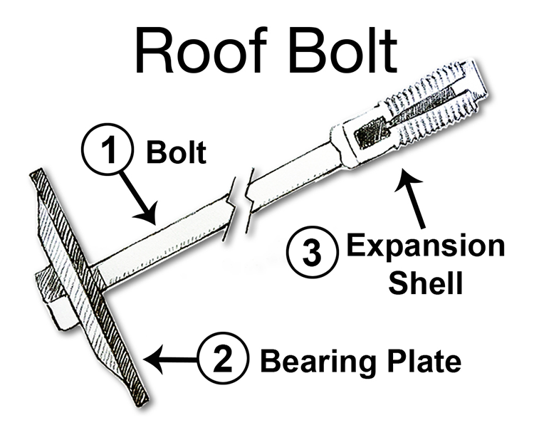
It works as follows. A hole is drilled into the rock mass that is to be supported. Next, the roof bolt is inserted into the hole. Then the bolt head is rotated, which causes the expansion shell to expand into the surrounding rock, locking it in place, and as the bolt rotates, it draws in the bearing plate. As a result, the layers between the expansion shell and the bearing plate are compressed tightly together, forming a beam. For this to work, the expansion shell must be anchored in competent rock. Sometimes, this can be done over 4’ and other times, 6’ or more. The length of the bolt is chosen with this in mind. The diameter of the bolt, which is between ½ - 1”, is based on the required tensile strength of the bolt, which is determined by calculating the weight of overlying rock that each bolt will have to support. In the future, you will learn how to size rock bolts. At this time, the takeaway message is:
- bolting is an active support because it is increasing the strength of the rock mass to prevent failure by clamping weak layers together to form a strong beam; and
- bolting is the most prevalent means of ground control in the majority of underground mines, and also in certain surface mines.
Under difficult conditions, we can place a skinny bag of resin, i.e., a strong glue, into the hole with the bolt; and then, as the bolt spins while it is being tightened, the bag will break and the resin will be mixed and will completely fill the hole around the bolt. Moreover, this resin will plug cracks and fractures in the rock in the immediate vicinity to further enhance the bolt’s holding power.
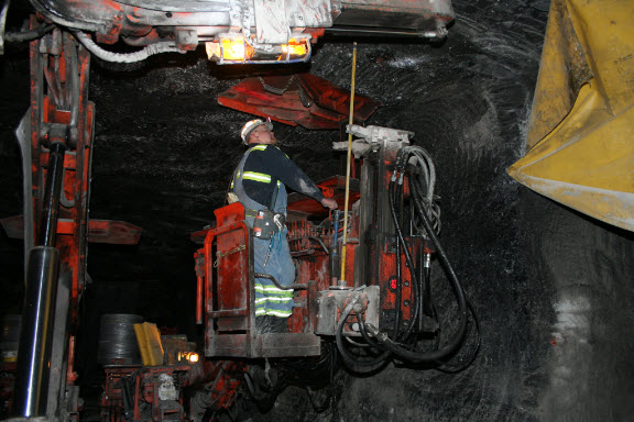
Here is a picture of roof bolting machine, commonly known as roof bolter or simply, a bolter. If you look closely, you will see the drill in front of the operator. Notice the attachment point to the machine at the bottom, i.e., the chuck. As the hole is drilled, that chuck assembly will move up towards the collar of the hole. After the hole is drilled, the operator will place a bolt in the chuck, insert it into the hole, and tighten it. The machine has plenty of space to store a supply of bolts along with the drill tools. You will also notice hydraulic canopies pressing into the top or “roof” of the mine opening. Those are passive supports to ensure that the top does not fall down while the bolter operator is installing the roof bolts.
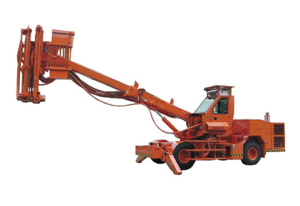
In so-called large opening mines, where the distance between the bottom and top of the mine opening might be 20 – 30’ or more, a slightly different configuration is required, as shown here. The operator would stand in the “cherry picker basket" and operate the drill and bolter.
Cable Bolts
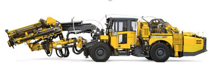
Sometimes, we need a bolt that is much longer than 4 – 6’. Remember, I said that for the bolt to achieve its purpose, the anchor must be in a competent rock layer. What if that layer is 15’, or 50’ or even 100’ above the opening? A bolt of such lengths would be impractical. Instead, we use a cable bolt. A reel of specially constructed steel cable is stored on a cable-bolting machine. A hole of the required length is drilled, an anchor shell is attached to the end of the cable, and it is fed to the end of the hole. An anchor plate and tensioning bolt is affixed to the end, and it is tensioned in some fashion as a traditional rock bolt. One difference, however, is that concrete grout will be pumped into the hole as well. Here is an example of a cable bolter. If you look closely, you can see the cable routed from the spool on the rear of the machine, up over the machine, and to the front where it will be inserted into the hole. The carriage housing the drill steel and the drill are also visible at the front of the machine.
Shotcrete
Shotcrete is another active support of note. Pillars of rock or ore are often left standing to help support the overlying strata, and only the ore between the pillars is recovered. The pillars can be under a lot of stress, and in some cases will begin to fail. The outer layers tend to crack and spall off, until the pillar is much skinnier and more likely to fail. The spalling of the outer layers can also present an immediate safety problem. One means of active support is to spray a Shotcrete onto the pillar. The Shotcrete may be cement or polymer mix, and fibers of various materials may be embedded in the mix. Thicknesses of an inch or more would be typical. Once the Shotcrete has dried, or really cured, it is quite strong and provides a confinement stress on the pillar. Sometimes the top surface of the span will be shotcreted as well.
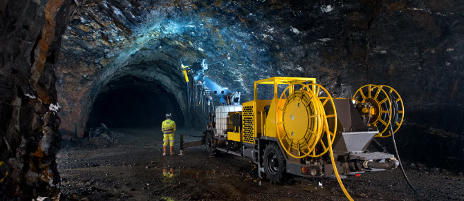
Here is a picture of a shotcrete operation in progress. You may be able to see the nozzle at the end of the boom, the mixing tank, and the dry feed hopper, and water line on the equipment. The other line is an electric power cable. The hose and cable reels provide sufficient mobility to the machine to allow it to move freely among working places, at least until the limit of the hose and cable are reached. Then, it will be necessary to advance the electrical and water supplies. Advancing utilities, such as electric power and water, is another important auxiliary operation that we will discuss shortly.
We’ve covered the majority of the ground control technologies with this brief introduction to active supports such as roof bolts, cable bolts, and shotcrete; and passive supports such as timber or steel posts and arches. There are others, but this group is illustrative. There is one more ground control technique that deserves a brief mention before we move on to other auxiliary operations, and that is backfilling.
Backfilling
Backfilling is the process of adding support to a mined out area by filling it with backfill, i.e., waste rock, tailings, or a mixture of cement and tailings or waste rock. As you might suspect, the time and cost to backfill is very expensive. Nonetheless, it is a part of the cut and fill mining method, in which we routinely mine a slice of ore, backfill it, and mine out the next slice, and so on. We’ll talk more about backfilling when we discuss this mining method. For now, you should simply be aware of backfilling as another ground control practice.
Also, I want to be clear that while the ground control challenge in underground mining is generally far more complicated than in surface mining, ground control practices including inspection and scaling are part of surface mining, and the use of rock bolts is part of some surface operations.
After this brief tutorial of ground control, you’ve probably forgotten how we got started on this discussion in the first place! Ground control is a critical auxiliary operation, and although we usually speak generally of ground control, in total, we’ve now seen that there are three components: inspection, scaling and installing ground support. Depending on the mining method and the competency of the rock, the activities associated with ground control may occur at differing time points in the production cycle.