Ease, accuracy, and worldwide availability have made ‘GPS’ a household term. Yet, none of the power or capabilities of GPS would have been possible without traditional surveyors paving the way. The techniques and tools of conventional surveying are still in use and, as you will see, are based on the very same concepts that underpin even the most advanced satellite-based positioning.
Geographic positions are specified relative to a fixed reference. Positions on the globe, for instance, may be specified in terms of angles relative to the center of the Earth, the equator, and the prime meridian.
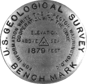
Land surveyors measure horizontal positions in geographic or plane coordinate systems relative to previously surveyed positions called control points, most of which are indicated physically in the world with a metal “benchmark” that fixes the location and, as shown here, may also indicate elevation about mean sea level (Figure 5.10). In 1988 NGS established four orders of control point accuracy, ranging in maximum base error from 3mm to 5cm. In the U.S., the National Geodetic Survey (NGS) maintains a National Spatial Reference System (NSRS) that consists of approximately 300,000 horizontal and 600,000 vertical control stations (Doyle,1994).
Doyle (1994) points out that horizontal and vertical reference systems coincide by less than ten percent. This is because:
....horizontal stations were often located on high mountains or hilltops to decrease the need to construct observation towers usually required to provide line-of-sight for triangulation, traverse and trilateration measurements. Vertical control points however, were established by the technique of spirit leveling which is more suited to being conducted along gradual slopes such as roads and railways that seldom scale mountain tops. (Doyle, 2002, p. 1)
You might wonder how a control network gets started. If positions are measured relative to other positions, what is the first position measured relative to? The answer is: the stars. Before reliable timepieces were available, astronomers were able to determine longitude only by careful observation of recurring celestial events, such as eclipses of the moons of Jupiter. Nowadays, geodesists produce extremely precise positional data by analyzing radio waves emitted by distant stars. Once a control network is established, however, surveyors produce positions using instruments that measure angles and distances between locations on the Earth's surface.
5.5.1 Measuring Angles and Distances
You probably have seen surveyors working outside, e.g., when highways are being realigned or new housing developments are being constructed. Often one surveyor operates equipment on a tripod while another holds up a rod some distance away. What the surveyors and their equipment are doing is carefully measuring angles and distances, from which positions and elevation can be calculated. We will briefly discuss this equipment and their methodology. Let us first take a look at angles and how they apply to surveying.
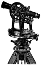
Although a standard compass can give you a rough estimate of angles, the Earth’s magnetic field is not constant and the magnetic poles, which slowly move over time, do not perfectly align with the planet’s axis of rotation; as a result of the latter, true (geographic) north and magnetic north are different. Moreover, some rocks can become magnetized and introduce subtle local anomalies when using compass. For these reasons, land surveyors rely on transits (or their more modern equivalents, called theodolites) to measure angles. A transit (Figure 5.11) consists of a telescope for sighting distant target objects, two measurement wheels that work like protractors for reading horizontal and vertical angles, and bubble levels to ensure that the angles are true. A theodolite is essentially the same instrument, except that it is somewhat more complex and capable of higher precision. In modern theodolites, some mechanical parts are replaced with electronics.
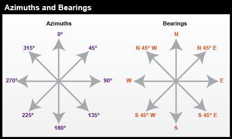
When surveyors measure angles, the resultant calculations are typically reported as either azimuths or bearings, as seen in Figure 5.12. A bearing is an angle less than 90° within a quadrant defined by the cardinal directions. An azimuth is an angle between 0° and 360° measured clockwise from North. "South 45° East" and "135°" are the same direction expressed as a bearing and as an azimuth.
5.5.2 Measuring Distances
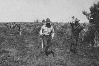
To measure distances, land surveyors once used 100-foot long metal tapes that are graduated in hundredths of a foot. An example of this technique is shown in Figure 5.13. Distances along slopes were measured in short horizontal segments. Skilled surveyors could achieve accuracies of up to one part in 10,000 (1 centimeter error for every 100 meters distance). Sources of error included flaws in the tape itself, such as kinks; variations in tape length due to extremes in temperature; and human errors such as inconsistent pull, allowing the tape to stray from the horizontal plane, and incorrect readings.
Since the 1980s, electronic distance measurement(EDM) devices have allowed surveyors to measure distances more accurately and more efficiently than they can with tapes. To measure the horizontal distance between two points, one surveyor uses an EDM instrument to shoot an energy wave toward a reflector held by the second surveyor. The EDM records the elapsed time between the wave's emission and its return from the reflector. It then calculates distance as a function of the elapsed time (not unlike what we’ve learned about GPS!). Typical short-range EDMs can be used to measure distances as great as 5 kilometers at accuracies up to one part in 20,000, twice as accurate as taping.
Instruments called total stations (Figure 5.14) combine electronic distance measurement and the angle measuring capabilities of theodolites in one unit. Next we consider how these instruments are used to measure horizontal positions in relation to established control networks.

5.5.3 Combining Angles and Distances to Determine Positions
Surveyors have developed distinct methods, based on separate control networks, for measuring horizontal and vertical positions. In this context, a horizontal position is the location of a point relative to two axes: the equator and the prime meridian on the globe, or to the x and y axes in a plane coordinate system.
We will now introduce two techniques that surveyors use to create and extend control networks (triangulation and trilateration) and two other techniques used to measure positions relative to control points (open and closed traverses).
Surveyors typically measure positions in series. Starting at control points, they measure angles and distances to new locations, and use trigonometry to calculate positions in a plane coordinate system. Measuring a series of positions in this way is known as "running a traverse." A traverse that begins and ends at different locations, in which at least one end point is initially unknown, is called an open traverse. A traverse that begins and ends at the same point, or at two different but known points, is called a closed traverse. "Closed" here does not mean geometrically closed (as in a polygon) but mathematically closed (defined as: of or relating to an interval containing both its endpoints). By "closing" a route between one known location and another known location, the surveyor can determine errors in the traverse.
Measurement errors in a closed traverse that connects at the point where it started can be quantified by summing the interior angles of the polygon formed by the traverse. The accuracy of a single angle measurement cannot be known, but since the sum of the interior angles of a polygon is always (n-2) × 180, it's possible to evaluate the traverse as a whole, and to distribute the accumulated errors among all the interior angles. Errors produced in an open traverse, one that does not end where it started, cannot be assessed or corrected. The only way to assess the accuracy of an open traverse is to measure distances and angles repeatedly, forward and backward, and to average the results of calculations. Because repeated measurements are costly, other surveying techniques that enable surveyors to calculate and account for measurement error are preferred over open traverses for most applications.
5.5.4 Triangulation
Closed traverses yield adequate accuracy for property boundary surveys, provided that an established control point is nearby. Surveyors conduct control surveys to extend and add point density to horizontal control networks. Before survey-grade satellite positioning was available, the most common technique for conducting control surveys was triangulation (Figure 5.16).
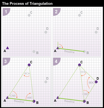
- Using a total station equipped with an electronic distance measurement device, the control survey team commences by measuring the azimuth alpha, and the baseline distance AB.
- These two measurements enable the survey team to calculate position B as in an open traverse.
- The surveyors next measure the interior angles CAB, ABC, and BCA at point A, B, and C. Knowing the interior angles and the baseline length, the trigonometric "law of sines" can then be used to calculate the lengths of any other side. Knowing these dimensions, surveyors can fix the position of point C.
- Having measured three interior angles and the length of one side of triangle ABC, the control survey team can calculate the length of side BC. This calculated length then serves as a baseline for triangle BDC. Triangulation is thus used to extend control networks, point by point and triangle by triangle.
5.5.5 Trilateration
An alternative to triangulation is trilateration, which uses distances alone to determine positions. By eschewing angle measurements, trilateration is easier to perform, requires fewer tools, and is therefore less expensive. Having read this chapter so far, you have already been introduced to a practical application of trilateration, since it is the technique behind satellite ranging used in GPS.
You have seen an example of trilateration in Figure 5.8 in the form of 3-dimensional spheres extending from orbiting satellites. Demo 1 below steps through this process in two dimensions.
Try This: Step through the process of 2-dimensional trilateration.
Once a distance from a control point is established, a person can calculate a distance by open traverse, or rely on a known distance if one exists. A single control point and known distance confines the possible locations of an unknown point to the edge of the circle surrounding the control point at that distance; there are infinitively many possibilities along this circle for the unknown location. The addition of a second control point introduces another circle with a radius equal to its distance from the unknown point. With two control points and distance circles, the number of possible points for the unknown location is reduced to exactly two. A third and final control point can be used to identify which of the remaining possibilities is the true location.
Trilateration is noticeably simpler than triangulation and is a very valuable skill to possess. Even with very rough estimates, one can determine a general location with reasonable success.
Practice Quiz
Registered Penn State students should return now take the self-assessment quiz Land Surveying.
You may take practice quizzes as many times as you wish. They are not scored and do not affect your grade in any way.