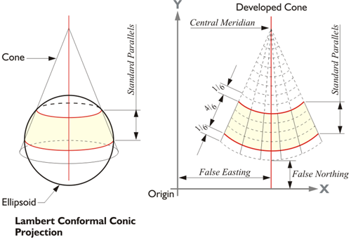
In 1932, two engineers in North Carolina’s highway department, O.B. Bester and George F. Syme, appealed to the then Coast & Geodetic Survey (C&GS, now NGS) for help. They had found that the stretching and compression inevitable in the representation of the curved earth on a plane was so severe over long route surveys that they could not check into the C&GS geodetic control stations across a state within reasonable limits. The engineers suggested that a plane coordinate grid system be developed that was mathematically related to the reference ellipsoid, but could be utilized using plane trigonometry rather than laborious geodetic calculations because in those days such calculations required sharp pencils, logarithmic tables and lots of midnight oil. Dr. Oscar Adams of the Division of Geodesy, assisted by Charles Claire, designed the first State Plane Coordinate System to mediate the problem. It was based on a map projection called the Lambert Conformal Conic Projection. Adams realized that it was possible to use this map projection and allow one of the four elements of area, shape, scale, or direction to remain virtually unchanged from its actual value on the earth, but not all four. On a perfect map projection, all distances, directions, and areas could be conserved. They would be the same on the ellipsoid and on the map. Unfortunately, it is not possible to satisfy all of these specifications simultaneously, at least not completely. There are inevitable choices. It must be decided which characteristic will be shown the most correctly, but it will be done at the expense of the others. And there is no universal best decision. Still, a solution that gives the most satisfactory results for a particular mapping problem is always available.
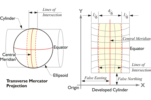
On the Lambert Conformal Conic Projection, parallels of latitude are arcs of concentric circles, and meridians of longitude are equally spaced straight radial lines, and the meridians and parallels intersect at right angles. The axis of the cone is imagined to be a prolongation of the polar axis. The parallels are not equally spaced because the scale varies as you move north and south along a meridian of longitude. Adams decided to use this map projection in which shape is preserved based on a developable cone. The Transverse Mercator projection is based on a cylindrical mapping surface much like that illustrated here. However, the axis of the cylinder is rotated so that it is perpendicular with the polar axis of the ellipsoid. Unlike the Lambert Conic projection, the Transverse Mercator represents meridians of longitude as curves rather than straight lines on the developed grid. The Transverse Mercator projection is not the same thing as the Universal Transverse Mercator system (UTM). UTM was originally a military system that covers the entire earth and differs significantly from the Transverse Mercator system used in State Plane Coordinates.
In using these projections as the foundation of the State Plane Coordinate systems, Adams wanted to have the advantage of conformality and also cover each state with as few zones as possible. A zone in this context is a belt across the state that has one Cartesian coordinate grid with one origin and is projected onto one mapping surface. One strategy that played a significant role in achieving that end was Adams’s use of secant projections in both the Lambert and Transverse Mercator systems. Using a single secant cone in the Lambert projection and limiting the extent of a zone, or belt, across a state to about 158 miles, approximately 254 km, Dr. Adams limited the distortion of the length of lines. Not only were angles preserved in the final product, but also there were no radical differences between the length of a measured line on the Earth’s surface and the length of the same line on the map projection. In other words, the scale of the distortion was small.
He placed 4/6th of the map projection plane between the standard lines, 1/6th outside at each extremity. The distortion was held to 1 part in 10,000. A maximum distortion in the lengths of lines of 1 part in 10,000 means that the difference between the length of a 2-mile line on the ellipsoid and its representation on the map would be about 1 foot. State Plane Coordinates were created to be the basis of a method that approximates geodetic accuracy more closely than the then commonly used methods of small-scale plane surveying. Today, surveying methods can easily achieve accuracies far beyond those prevalent in those days, but the State Plane Coordinate systems were designed in a time of generally lower accuracy and efficiency in surveying measurement.
The original State Plane Coordinate System (SPCS) was so successful in North Carolina, similar systems were devised for all the states in the Union within a year or so. The system was successful because, among other things, it overcame some of the limitations of mapping on a horizontal plane while avoiding the imposition of strict geodetic methods and calculations. It managed to keep the distortion of the scale ratio under 1 part in 10,000 and preserved conformality. It did not disturb the familiar system of ordered pairs of Cartesian coordinates, and it covered each state with as few zones as possible whose boundaries were constructed to follow county lines. County lines were generally used, so that those relying on State Plane Coordinates could work in one zone throughout a jurisdiction.