L2 Signal
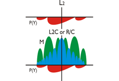
In the illustration, the L2 signal diagram is centered on 1227.60 MHz. As you can see, it is similar to the L1 diagram except for the absence of the C/A code, which is, of course, not carried on the L2 frequency. As well-known as these are, this state of affairs is changing. We have been using the L2 carrier since the beginning of GPS, of course, but there will be two new codes broadcast on the carrier, L2, that previously only carried one military signal exclusively, the P(Y) code. L2 will carry a new military signal, the M-code, just discussed, and a new civil signal as well.
On the upper portion of this diagram, you see the L2 carrier, of course, with only the P-Code encrypted as the Y-Code. In the lower part, there is the same L2 with P-Code, but the M-Code is included, and there's a new civilian code. This one is called L2C. Before this, there was no civilian code on L2. There was only the C/A Code on L1. However, these new IIR-M satellites will be carrying the L2C, a civil code on L2. We've been using the L2 carrier since the beginning of GPS, of course, but there will be two new codes broadcast on that carrier, the M-Code and the new Civilian code L2C.
L2C
A new military code on L1 and L2 may not be terribly exciting to civilian users, but these IIR-M satellites have something else going for them. They broadcast a new civilian code. We have been using the L2 carrier since the beginning of GPS of course, but there will be two new codes broadcast on the carrier, L2, that previously only carried one military signal, the P(Y) code. L2 will carry the new military signal, the M-code, and a new civil signal as well. This is a code that was first announced back in March of 1998. It is transmitted by all block IIR-M satellites and subsequent blocks and is known as L2C. The “C” is for civil.
Even though its 2.046 MHz from null-to-null gives it a very similar power spectrum to the C/A code, it is important to note that L2C is not a copy of the C/A-code even though that was the original idea. The original plan was that it would be a replication of the venerable C/A code, but carried on L2 instead of L1. This concept changed when Colonel Douglas L. Loverro, Program Director for the GPS Joint Program Office (JPO), was asked if perhaps it was time for some improvement of C/A. The answer was yes. The C/A code is somewhat susceptible to both waveform distortion and narrow-band interference, and its cross-correlation properties are marginal at best. So, the new code on L2, known as L2 civil, or L2C was announced. It is more sophisticated than C/A. So, the L2C is actually a different code than the C/A. Still, it's a civilian accessible code, and it's carried on L2 instead of L1.
Civil-Moderate (CM) and Civil-Long (CL)
L2C is actually composed of two pseudorandom noise signals: the civil-moderate length code, CM, and the civil long code, CL. They both utilize the same modulation scheme, binary phase shift key (BPSK), as the legacy signals, and both signals are broadcast at 511.5 kilobits per second (Kbps). This means that CM repeats its 10230 chips every 20 milliseconds, and CL repeats its 767250 chips every 1.5 seconds. But, wait a minute, how can you do that? How can you have two codes in one?
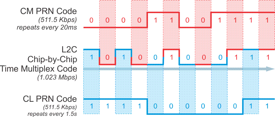
L2C achieves this by time multiplexing. Since the two codes have different lengths L2C alternates between chips of the CM code and chips of the CL code as shown in the illustration. It is called chip-by-chip time multiplexing. So, even though the actual chipping rate is 511.5 KHz, half the chipping rate of the C/A code, with the time multiplexing it still works out that taken together L2C ends up having the same overall chip rate as L1 C/A code, 1.023 MHz . This provides separation from the M code.
In this illustration, I try to answer the question how it's possible in L2C to have two codes, the CM Code and the CL Code, simultaneously operating on the same signal. It's known as multiplexing, and we discussed that briefly when we were talking about receivers, except, in this case, it's chip by chip time multiplexing. The CM Code, the moderate length code, goes through 10,238 chips before it repeats. It repeats every 20 milliseconds, but the CL Code, the long code, repeats after 1.5 seconds.
Those lengths give you very good cross correlation protection. In fact, both are longer than the C/A Code and present a subsequent improvement in autocorrelation. This is because the longer the code, the easier it is to keep the desired signal separate from the background. In practice, this means that these signals can be acquired with more certainty by a receiver which can maintain locking them more surely in marginal situations where the sky is obstructed.
So, it is possible to have these two signals, the CM and the CL on the L2C because the receiver can shift back and forth between the two with good, solid cross correlation and lock on to the signals even in circumstances where the sky is obstructed better than one can with the C/A Code. It's important to note that the L2C is actually slightly weaker, 2.3 decibels weaker, than the C/A Code. And it's surprising that this is not a disadvantage, because the receiver can track the long dataless CL, that's the long code on L2C with the phase locked loop instead of squaring Costas loop.
In other words, the long dataless sequence of the CL provides for correlation that is actually about 250 times stronger than the C/A Code. So, despite the fact that its transmission power is 2.3 decibels weaker compared to the C/A Code, the L2C has 2.7 decibels greater data recovery and 0.7 decibels greater carrier tracking. It's actually more solid, even though the power is slightly less.
L2C has better autocorrelation and cross-correlation protection than the C/A code because both of the CM and CL codes are longer than the C/A code. Longer codes are easier to keep separate from the background noise. In practice, this means these signals can be acquired with more certainty by a receiver that can maintain lock on them more surely in marginal situations where the sky is obstructed.
There is also another characteristic of L2C that pays dividends when the signal is weak. While CM carries newly formatted navigation data and is, therefore, known as the data channel, CL does not. It is dataless and known as a pilot channel. A pilot channel can support longer integration when the signal received from the satellite is weak. This is an idea that harks all the way back to Project 621B at the very beginnings of GPS. The benefits of a pilot channel distinct from the data components carried by a signal was known in the 1960s and 1970s but was not implemented in GPS until recently.
Phase-Locked Loop
Even though the L2C signals’ transmission power is 2.3 dB weaker than is C/A on L1, and even though it is subject to more ionospheric delay than the L1 signal, L2C is still much more user friendly. The long data-less CL pilot signal has 250 times (24dB) better correlation protection than C/A. This is due in large part to the fact that the receiver can track the long data-less CL with a phase-locked loop instead of a squaring Costas loop that is necessary to maintain lock on CM, C/A and P(Y). This allows for improved tracking from what is, in fact, a weaker signal and a subsequent improvement in protection against continuous wave interference. As a way to illustrate how this would work in practice, here is one normal sequence by which a receiver would lock onto L2C. First, there would be acquisition of the CM code with a frequency locked or Costas loop, next there would be testing of the 75 possible phases of CL, and finally acquisition of CL. The CL, as mentioned, can be then tracked with a basic phase-locked loop. Using this strategy, even though L2C is weaker than C/A there is actually an improvement in the threshold of nearly 6 dB by tracking the CL with the phase-locked loop. Compared to the C/A code L2C has 2.7 dB greater data recovery and 0.7 dB greater carrier-tracking.
Practical Advantages
Great, so what does all that mean in English? Having two civilian frequencies being transmitted from one satellite affords the ability to model and lessen the ionospheric delay error for that satellite while relying on code phase pseudorange measurements alone. In the past, ionospheric modeling was only available to multi carrier frequency observations, or by reliance on the atmospheric correction in the Navigation message. Before May 2, 2000 with Selective Availability on a code-based receiver could get you within 30 to 100 meters of your true position; when SA was turned off, that was whittled down to 15 to 20 meters or so under very good conditions. But with just one civilian code C/A on L1, there was no way to remove the second largest source of error in that position, the ionospheric delay.
But with two civilian signals, one on L1 (C/A) and one on L2 (L2C), it becomes possible to effectively model the ionosphere using code phase. In other words, it may become possible for an autonomous code-phase receiver to achieve positions with a 5-10m positional accuracy with some consistency.
The L2C signal also ameliorates the effect of local interference. This increased stability means improved tracking in obstructed areas like woods, near buildings, and urban canyons. It also means fewer cycle slips.

With L2C, there will be a better tolerance for interference, increased stability, and fewer cycle slips. That means that GPS will work better in obstructed areas, and this will be a practical advantage to those like the fellow with his receiver looking up to an obstructed sky. A second civilian code on a separate frequency is another really practical advantage. You can model the ionosphere with a multi-frequency receiver because of the dispersive characteristic of the ionosphere. However, those that have been operating purely in code phase or pseudo range positions have not had that advantage. Now, with L2C on L2, and C/A Code on L1, there will be two civilian accessible codes available to a code phase pseudo range receiver making it possible to model the ionosphere with a code observation. This should improve the positions available from purely code phase receivers quite a bit.
So, even if it is the carrier-phase that ultimately delivers the wonderful positional accuracy we all depend on, the codes get us in the game and keep us out of trouble every time we turn on the receiver. The codes have helped us to lock on to the first satellite in a session and allowed us to get the advantage of cross-correlation techniques almost since the beginning of GPS. In other words, our receivers have been combining pseudorange and carrier-phase observables in innovative ways for some time to measure the ionospheric delay, detect multipath, do wide laning, and so forth. But those techniques can be improved, because while the current methods work, the results can be noisy and not quite as stable as they might be, especially over long baselines. It will be cleaner to get the signal directly once there are two clear civilian codes, one on each carrier. It may also help reduce the complexity of the chipsets inside our receivers, and might just reduce their cost as well.
Along that line, it is worthwhile to recall that the L2C has an overall chip rate of 1.023 MHz, just like L1 C/A. Such a slow chip rate can seem to be a drawback until you consider that that rate affects the GPS chipset power consumption. In general, the slower the rate, the longer the battery life, and the improvement in receiver battery life could be very helpful. And not only that, the slower the chip rate, the smaller the chipset. That could mean more miniaturization of receiver components.
L2C is clearly going to be good for the GPS consumer market, but it also holds promise for surveyors. Nevertheless, there are a few obstacles to full utilization of the L2C signal. It will be some time before the constellation of Block IIR-M necessary to provide L2C at an operational level is up and functioning. Additionally, aviation authorities do not support L2C. It is not in an Aeronautical Radionavigation Service (ARNS) protected band. It happens that L2 itself occupies a radiolocation band that includes ground-based radars.
Click here to see a text description.
| Messages (pseudo-packetized) | 1 Word | 2 Words | 3-10 Words |
|---|---|---|---|
| 0 | MT | How | Default |
| 10 | MT | How | Ephemeris 1 |
| 11 | MT | How | Ephemeris 2 |
| 13 | MT | How | Clock Differential Correction |
| 14 | MT | How | Ephermis Differential Correction |
| 15 | MT | How | Text |
| 30 | MT | How | Clock, IONO, &Group Delay |
| 31 | MT | How | Clock & Reduced Almanac |
| 63 | MT | How | MT7-67 still to be defined |
CNAV
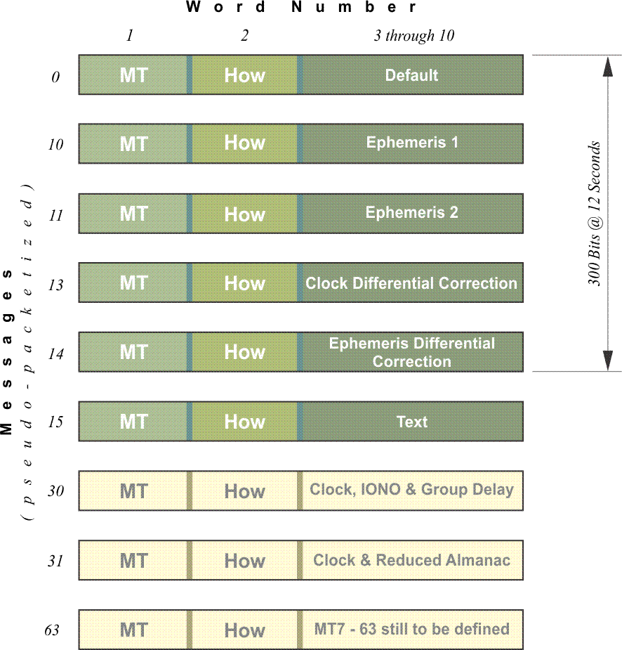
The navigation data on CM portion of the L2C signal is improved over the legacy Navigation message. It is called CNAV. It was tested using some of the message types, MT, shown in the illustration in June of 2013.
You may recall that the legacy Navigation message was mentioned in Chapter 1. It is also known by the acronym NAV. The information in CNAV is fundamentally the same as that in the original NAV message, but there are differences. It includes the almanac, ephemerides, time, and satellite health. CNAV contains 300-bit messages like the legacy NAV message, but CNAV packages its 12-second, 300-bit messages differently. Instead of the repetition of frames and sub-frames in a fixed pattern as is the case with the legacy NAV, CNAV utilizes a pseudo-packetized message protocol. One of every four of these packets includes clock data; two of every four contains ephemeris data, and so on. This makes CNAV more flexible than NAV. The order and the repetition of the individual messages in CNAV can be varied. CNAV can accommodate the transmission of the information in support of 32 satellites using 75% or less of its bandwidth. CNAV is also more compact than NAV, and that allows a receiver to get to its first fix on a satellite much faster.
A packet in message 35 of CNAV was assigned to the time offset between GPS and GNSS in the June 2013 test. Such a message would be a boon for interoperability between GPS, Galileo, and GLONASS. Also, each packet contains a flag which can be toggled on within a few seconds of the moment a satellite is known to be unhealthy. This is exactly the sort of quick access to information necessary to support safety-of-life applications. Only a fraction of the available packet types are being used at this point. CNAV is designed to grow, and can accommodate 63 satellites as the system requires. For example, there could be packets that would contain differential correction like that available from satellite-based augmentation systems (SBAS).
There is also a very interesting aspect to the data broadcast on CM known as Forward Error Correction (FEC). An illustration of this technique is to imagine that every individual piece of data is sent to the receiver twice. If the receiver knows the details of the protocol to which the data ought to conform, it can compare each of the two instances it has received to that protocol. If they both conform, there is no problem. If one does and one does not, the piece of data that conforms to the protocol is accepted and the other is rejected. If neither conforms, then both are rejected. Using FEC allows the receiver to correct transmission errors itself, on the fly. FEC will ameliorate transmission errors and reduce the time needed to collect the data.
There is a packet in CNAV that may be assigned to the time offset between GPS and GNSS. So, one of the things we'll talk about is that GLONASS's time standard is different than that of GPS, and the difference can be loaded into the navigation message, so there's some preparation here for the GNSS future. Each packet contains a flag that can be turned on and off very quickly to indicate that a satellite is unhealthy. This could be quite useful for safety of life, things such as ambulances and so on. Because if a satellite should not be used in positioning if it will corrupt the results, it's important to know that immediately in real time. It's great to have a system that can provide that.