The Z-Stop protects the optical profilometer in the Z direction. It needs to be set for each sample, with care taken to set a proper distance.
Set Z-Stop (CRITICAL)
- Verify the working distance of the objective. (See table below.)
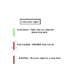
- Check Z-Stop status (what color is Z-stop light on joystick?).
- Red = At Z-stop position.
- Green = Above Z-stop position.
- Flashing Red = No Z-stop is set. USE EXTREME CAUTION (instrument will beep as you move in Z).
- Only pay attention to the space between the objective and the top of your sample. No need to look at the PC, your cell phone, your friend next to you. Just focus on the objective-sample gap.
- The ideal Z-stop position is defined as a distance between objective and sample surface that is less than the working distance and allows for the scan to reach just below the lowest region of the surface. Too low a Z-stop can put the instrument at risk; a Z-stop too close to the Working Distance could lead to software errors when you try to scan.
- Use Fast only at distances greater than 20mm from the sample. Press Z-stop button so the light is flashing RED and begin a downward focus until you arrive at approximately 20mm. Push Medium and continue towards the surface until an appropriate Z-stop position. Never use “FAST” speed when nearing sample surface (<20mm)
- Press Z-stop so the light is now solid RED.
- Use focus aid and raise Z to focus.
What is a good Z-Stop position?
The simple answer here is one that allows the instrument to scan low enough to scan through all parts of your surface AND prevents the instrument from being driven into your sample. Below are illustrated examples of an improper and proper Z-stops.
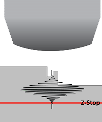
This would be a bad Z-Stop setting to use. It is too close to the lowest part of the surface and doesn't allow the scanner to move through the surface plane fully.
PSU MCL
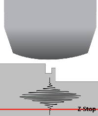
We have corrected the Z-Stop here by setting it lower, allowing the fringes to scan completely through the surface topography. We have also set it so the objective can not be scanned or driven into the surface of the sample.
PSU MCL
Most important thing to remember when setting the Z-Stop is to remember you do this manually by watching the objective and your sample directly. It is never to be set watching the computer screen with the software.
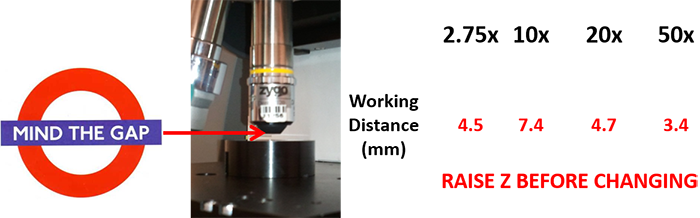
Mind the gap!
PSU