Review of some important concepts
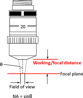
The working distance is the distance from the front of the lens housing down to the focal plane of the objective. We commonly use working distance, focal plane, and zero optical path difference interchangeably. The focal plane of the objective must scan all the way through the sample surface (from above, down through, and then below the highest and lowest parts of the surface in the FoV of the scan or stitch).
Z-Stop
The Z-Stop is a hard stop for both the user and the software, set before working in the software, to allow the focal plane to scan through the required scan length but prevent any part of the instrument from making contact with any part of the sample or sample mounts that may be in use.
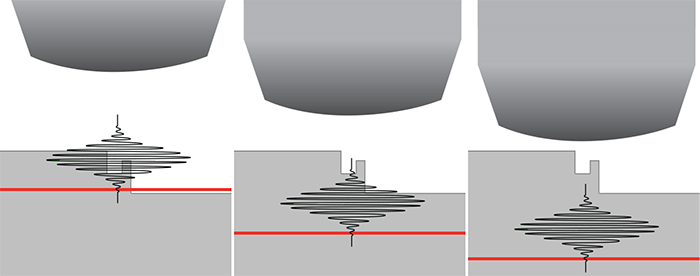
In the above image, we have three different Z-stop (denoted by the red line) settings. On the left, the Z-stop is set too close to the surface, and you will not get any good data. In the middle, the lower Z-stop allows you to collect some information from the higher parts of the sample surface, but it does not take into account the proper distance the width of the fringes must travel through to reach the lowest part of the sample. The image on the left shows a Z-stop that not only allows the instrument to scan the width of the fringes through all of the surface topography, but also protects the objective from being driven into the sample by the user or the software.
Scan Length
Scan length is discussed in the section on MX™ measure tab, but we will take this into consideration here for a moment to get you thinking about things to come.
Once you have a proper Z-stop set. Setting up the proper scan requires the user to set up a proper scan start position and scan length so the width of the fringes can be scanned entirely through the surface topography. An illustration of what the system looks like scanning is depicted below. Notice how the instrument moves with respect to start and end scan. This will be covered in more detail in the next sections.