The study of the geological processes that create crude oil and natural gas reservoirs is referred to as Petroleum Geology. In this discussion, we will also need to include brief discussions of related, specialized areas of geologic study including Stratigraphy and Structural Geology. Stratigraphy is the study of the layers (or strata) within rock formations; while Structural Geology is the study of the deformation of rock under tectonic forces. You are probably most familiar with the concepts of stratigraphy and structural geology from road-cuts seen along highways. These road-cuts often show cross-sectional outcrops of layered, deformed rock formations along the road-side. The layering you see is the local geologic stratigraphy; while the deformations you see form the local geologic structure of the rock formations.
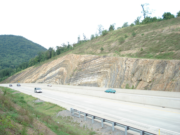
Figure 2.04 shows a road-cut along Route 322 approximately 39 miles south of State College, PA. In this photograph, the layering (stratigraphy) and deformation (structure) of the Keefer Formation (Silurian Age) are clearly evident. The “inverted bowl-shaped” feature in this photo is an anticlinal structure, or simply an anticline. Anticlines statistically form the most common crude oil and natural gas reservoirs. We will discuss this in more detail when we discuss Reservoir Traps later in this lesson.
As we have already discussed, hydrocarbon reservoirs are typically associated with sedimentary rock formations. Over geologic time, weathered and eroded rock materials are carried downstream from elevated regions to lower regions in rivers and streams to oceans, seas, or lakes. At the point in the rivers, oceans, seas, or lakes where the energy in the water can no longer suspend or transport the rock material, it begins to settle in the water and is deposited onto the bottom of the water body. This is called the depositional process. During the depositional process, the environment can change over the geologic time scale: mountain tops and hilltops erode, sea-levels rise or lower, etc. With these changes, the types of sediments that are deposited change and the locations where they are deposited also change. Two commonalities that exist during the depositional process, even over the geologic time scale, are (1) the sediments and, consequently, the sedentary rocks that are lower in the stratigraphic column were deposited earlier than sediments higher in the stratigraphic column and (2) the layers of sediment are initially deposited horizontally. From this discussion, we can see that sediments lower in the stratigraphic column must be older than those higher in the stratigraphic column.
Note, a stratigraphic column is a written, pictorial, or schematic record of the local rock strata showing the order of the rock deposition (older rocks at the bottom and younger rocks at the top), along with notes concerning the age of the rocks, occurrence of any fossils, any rocks which may be absent from the local geological record due to erosion, or any notes of use to a geologist. One example of a stratigraphic column that you may be familiar with is The Obelisk on the University Park Campus of Penn State. The Obelisk is a physical column constructed of quarried building materials from Pennsylvania with the older rocks placed at the base of the column and the younger rocks placed at the top of the column. Consequently, it forms a true stratigraphic column of the building stones of Pennsylvania. A photograph of The Obelisk is shown in Figure 2.05.

From this discussion, we can also see that in their original, natural state, sedimentary rocks are horizontal. Any deformation (folding, uplifting, tilting, faulting, etc.) in sedimentary rock formations is caused by tectonic forces acting on the rock after deposition and solidification.
There are five geological requirements for the formation of a conventional hydrocarbon reservoir:
- Source Rock
- Migration Path
- Cap Rock
- Reservoir Rock
- Trap
These geological requirements are illustrated in Figure 2.06. It needs to be emphasized that although this figure consists of solid colored bands, these bands represent either porous or non-porous rocks. In the following discussions, all of the action concerning this figure is occurring in the pore-spaces of porous rock.
In this figure, the Source Rock is represented by the light grey layer. This is the rock in which the original organic material is converted into hydrocarbons. We will discuss this process later in this lesson. As we can see from this figure, the hydrocarbons do not necessarily originate in the hydrocarbon reservoir itself but are generated away from the reservoir in rocks that are conducive to hydrocarbon generation. As we will discuss later, these source rocks are typically organic-rich shales, siltstones, or coals.
Since the hydrocarbons are generated away from the reservoir, there must be a pathway for the hydrocarbons to migrate from the source to the reservoir. This pathway is the Migration Path in the hydrocarbon system. In the example shown in Figure 2.06, the migration path is a water-filled rock layer (aquifer) that is in communication with both the source rock the hydrocarbon bearing reservoir. This aquifer is shown as the blue layer in Figure 2.06.
In Figure 2.06, the solid green arrows represent the primary migration of the hydrocarbons, while the dashed green arrows represent the secondary migration of the hydrocarbons. Primary migration refers to the initial expulsion of the hydrocarbons from the source rock, while secondary migration refers to the remainder of migration to the reservoir.
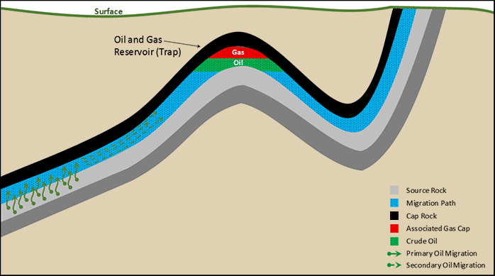
As shown in this figure, all fluid migration is upward. This is because the main driving mechanism in hydrocarbon migration is buoyancy, which occurs because the oil and gas are less dense (lighter) than the resident water. In order to prevent this buoyant flow from occurring all of the way to the surface, a vertical flow barrier, or Cap Rock, is required along the migration path and at the reservoir itself. A cap rock is simply an overlying rock layer that is impermeable to flow. Permeability is a property of the rock that is a measure of the ease in which fluids can flow through a porous medium (in our case, a rock formation). In Figure 2.06, the cap rock is depicted by the black layer.
The fourth requirement for a hydrocarbon accumulation is the presence of a Reservoir Rock. In the example shown in Figure 2.06, the reservoir rock is the same rock formation as the migration path. As stated earlier, the most common reservoir rocks are sedimentary rocks; however, naturally fractured igneous and metamorphic rocks can also form hydrocarbon reservoirs. The two requirements for a commercial crude oil or natural gas reservoir are high porosity and high permeability. As discussed earlier, oil and natural gas exist in the pore-space between the grains of the sedimentary rocks. The porosity of a rock is defined as the fraction of the rock’s bulk (total) volume occupied by the pores. For example, a cubic foot (1 ft3) of rock with 15 percent porosity will contain 0.15 ft3 of pore space. Consequently, a rock formation with a higher porosity implies greater storage capacity than a rock formation with a lower porosity. This, in turn, results in the possibility of greater quantities of oil and gas stored in the more porous rock.
As discussed earlier, permeability is defined as the ease in which fluids flow through porous media. A high permeability formation implies greater oil and gas production rates and more economically attractive production wells.
The last component of a hydrocarbon system is the Trap. A trap or trapping mechanism is a change in the stratigraphy or a structural deformation that is capable of stopping the migration process and keeping the oil and gas in place over geologic time. In the example in Figure 2.06, the trap is an anticline like that shown in the photograph in Figure 2.04.
Statistically, anticlines are the most common traps; however, they are not the only types of hydrocarbon traps. Crude oil and natural gas traps can be categorized as Stratigraphic Traps or Structural Traps. As the names imply, stratigraphic traps are related to the layering of the rock strata; while structural traps are related to the structural deformations of the rock formations.
Examples of stratigraphic hydrocarbon traps are shown in Figure 2.07. Figure 2.07 shows (a) a “pinch-out” trap and (b) an unconformity trap. In these figures, the yellow layers represent reservoir quality rock (Reservoir Rock); while the green areas represent an oil accumulation in the reservoir trap.
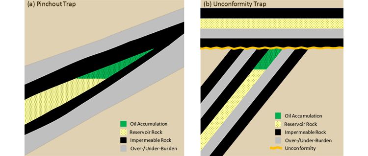
A pinchout trap, Figure 2.07a, is formed due to the relative rise and fall of a water body in relation to the local land mass. (Note: a relative rise or fall may be due to either a true rise or fall of the sea level, or a subsidence or uplift of the land mass.) In this figure, the crude oil reservoir is represented by the green area encased in the black, impermeable layer. As mentioned earlier in this lesson, the size and weight of the sediments that form sedimentary rocks are deposited in water are dependent on the energy of the water suspending the particles. Heavier, coarser materials can only be suspended in high energy environments near the shore where wave and tidal action keep these materials mixed with the water. These materials are deposited as sediments at the point in the depositional environment where the wave and tidal energy can no longer support them. On the other hand, lighter, finer sediments can be suspended in low energy environments away from the shore in more calm waters and, consequently, are deposited further from the shoreline. As the relative position of the sea level changes over the geologic time scale, the positions of the coarser and finer sediments change. The coarser materials with the larger pore spaces between the sediment grains often make good quality rock, while the finer materials, particularly clays and silts, with smaller pore spaces make good impermeable seals (cap rocks). Under the proper sequence of events, as the geographical locations of the sediments change over the geologic time scale, the changes in the size of the sediments can create pinchout, or stratigraphic trap.
Figure 2.07b shows an unconformity trap. A geological unconformity is a boundary between two rock sequences of different ages that are missing some transitory rock sequences of intermediate ages - in other words, some rock strata are missing from the local geological record. This gap in the geological record is caused by a past erosional period.
The depositional history of an unconformity trap is slightly more complicated than that of a pinchout trap. In this trap system, an early depositional period caused sedimentary rocks to be deposited horizontally. These rocks were then tilted due to local tectonic forces. These form the lower tilted layers in Figure 2.07b. The higher, uplifted portions of the tilted layers were then eroded over geological time. The orange wavy line represents an unconformity surface where rocks are missing from the geological record. Geologists recognize these unconformity surfaces when they see rocks of one age sitting on top of rocks of a different age with no intermediary age rocks between them; while paleontologists recognize unconformities by rocks containing fossils from one age sitting directly on top of rocks containing fossils from a different, much older age. After subsidence, a second depositional period occurs where additional sedimentary rocks are again deposited horizontally over the erosional surface. In order for an unconformity trap to develop, the first layer deposited during the second depositional period must be an impermeable rock which can act as the cap rock for the reservoir. After the second depositional period, the trap can be charged with crude oil to form the oil reservoir - the green area of the figure. (Note that the horizontal yellow layer representing good quality reservoir rock above the unconformity surface, does not contain crude oil or natural gas. This is because it is missing a trapping mechanism at this location.)
These histories illustrate the critical nature of the timing in the development of hydrocarbon reservoirs. For a hydrocarbon reservoir to develop, all five elements of the reservoir system must be in place prior to the formation and migration of the hydrocarbons. If one element is missing from the system, then a crude oil or natural gas reservoir cannot develop.
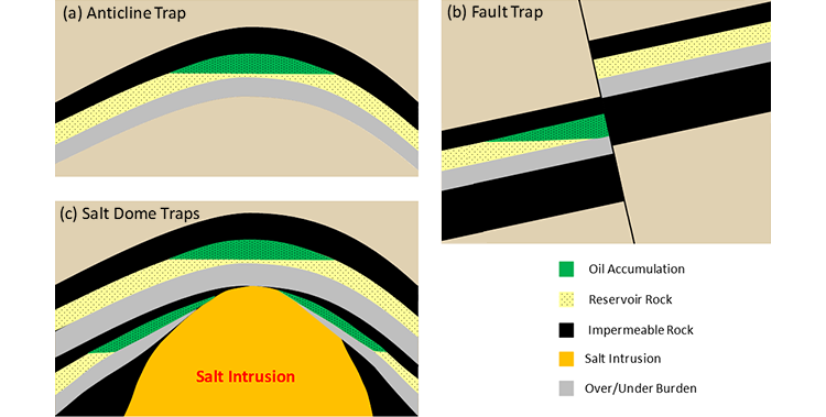
The second major category of hydrocarbon reservoirs is structural traps. Structural traps, illustrated in Figure 2.08, are related to mechanical deformations and failures of the reservoir rock. Figure 2.08a shows an anticlinal structure, or anticline. As stated earlier, the anticline is statistically the most common reservoir trap. The reason for this is very simple. An anticlinal trap simply requires that the reservoir rock and cap rock be folded in a manner that can trap the lighter hydrocarbons. Figure 2.04 shows the Arch Rock anticline near State College, PA.
Figure 2.08b shows a fault trap. A fault trap is created when a rock formation undergoes mechanical failure during an earthquake and the resulting fault causes a porous and permeable rock formation (reservoir rock) to be positioned adjacent to an impermeable rock formation. Thus, closure to the trap is formed by the cross-fault impermeable layer.
Figure 2.08c shows traps along a salt dome. These traps are common in areas where salt formations exist, such as in the Gulf of Mexico. Since large volumes of salt behave in a plastic manner over geologic time, the weight of the overburden creates great pressures within the salt causing it to flow through any local weak spots in the overburden. These salt intrusions can create hydrocarbon traps above and to the flanks of the intrusion as depicted in Figure 2.08c.