Gas condensate reservoirs are gas systems that reside in reservoirs with the original temperatures lying between the critical temperature, TC, and the cricondentherm (Tmax in Figure 2.11). If the original reservoir pressure is greater than the dew-point pressure, then a single-phase gas system will occur in the reservoir as in Figure 2.15.
In this figure, the reservoir is initially a single-phase gas, but as we deplete the pressure due to gas production the pressure-temperature path of the system enters the two-phase region of the phase envelope and liquid hydrocarbons condense from the gas in the reservoir (thus the name gas condensate reservoir.)

We are actually very familiar with this process in our everyday lives. Think of a four-component mixture of oxygen, carbon-dioxide, nitrogen, and water vapor (a mixture of air) and its phase envelope. If we started at a point in the single-phase gas region with a pressure below the cricondenbar (pmax in Figure 2.11) and reduced the temperature under constant pressure conditions (isobaric conditions), then we would cross the dew point locus of the phase envelope. This would be the pressure and temperature where we would see the first dew forming on plants and the first water condensation forming on glass and metal. If we were to continue reducing the temperature, then the percent volume of liquid (water) would increase and it would begin to rain. What is happening in this simple example is that the heaviest component in our system (water vapor) is condensing out of the gas phase (air mixture) and forming a second phase (liquid water) in the two-phase region.
This is essentially what is occurring in the reservoir of a gas condensate system but under isothermal conditions. As we pass through the dew point pressure, the heaviest hydrocarbon components in the system begin to drop out and form a second, liquid hydrocarbon phase in the two-phase region of the phase envelope inside the reservoir.
There is one interesting characteristic of gas condensate reservoirs that is worth further discussing and that is the retrograde behavior of these systems. This is illustrated in Figure 2.16. In this figure, if we were to follow the isothermal Path A-A’-A’’, then we would go below through the dew-point pressure, increase the volume percentage of the liquid hydrocarbon phase until it reached a maximum at Point A’ with further reductions in pressure resulting in a lower volume percentage of the liquid hydrocarbon phase. We could also continue the isothermal pressure reduction, reenter the single-phase gas region, and stop at Point A’’.
We can see from Figure 2.09 and Figure 2.10 that for a pure (single-component) system, the liquid phase occurs at higher pressures than the gas phase. Thus, if we were to start in the single-phase liquid region of a pure system, we would need to reduce the pressure isothermally to create a gas phase.
The analogy for our multi-component system is that if we start at the point of maximum liquid volume (Point A’ in Figure 2.16) and reduced the pressure isothermally, then we would get the conventional behavior for a pure system along Path A’-A’’. Conversely, if we were to start at Point A’ and increased the pressure isothermally to Point A in the single-phase gas region, then we would get the behavior opposite of that for a pure system along Path A’-A. This behavior, opposite to a pure system, is referred to as retrograde behavior. This behavior occurs in the green shaded region in Figure 2.16. This region, formed by connecting all of the points of maximum temperature on the quality lines, is referred to as the retrograde region of the fluid.
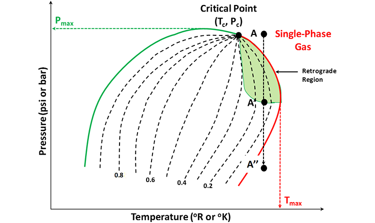
Sometimes we see or hear the terms “Retrograde Condensate Reservoir” or “Retrograde Condensate System.” This terminology is used to describe reservoirs in which the isothermal reservoir pressure-temperature path traverses the retrograde region of the system’s phase envelope.