Geodatabase Topology
A geodatabase topology is another construct that is stored within a geodatabase and gives us added control over assessing and maintaining the integrity of our spatial data.
Follow this link to download the data for this part of the lesson: Topology.zip
The zip archive contains the following:
An Esri File Geodatabase: geodatabasetopol.gdb
A zip archive: TopologyProject.zip
Controlling spatial data integrity by imposing rules - Geodatabase Topology
A geodatabase topology provides a robust way of defining topological relationships among spatial features. It does so by analyzing coordinate locations of feature vertices both among features within a feature class and between features in multiple feature classes taking part in the topology. Therefore, it is not only important that all of the feature classes participating in a geodatabase topology be in the same coordinate system, but also that the measurement precision defined for each feature class be the same. To assure that this is the case, all feature classes that take part in a geodatabase topology must reside within what is known as a Feature Dataset. When a feature dataset is created, the coordinate system and precision are defined, and any subsequent feature class that is added to the feature dataset inherits that coordinate system and precision. In the exercise that follows, you will see that the precision is controlled by the Tolerance and Resolution settings. I encourage you to read more about these topics in the Topology in ArcGIS entry in the ArcGIS Pro documentation.
A geodatabase topology is governed by topology "rules" that the user specifies, and those rules are based on knowledge of the relationships between and among the features that will be taking part in the topology. So, the onus is on the user to understand the data being created/edited in order that appropriate rules are specified.
The manifestation of a geodatabase topology is as a layer in the feature dataset. As such, the topology errors that it contains are symbolized just as are the features in any other map layer in ArcGIS. In the documentation, the Validate and fix geodatabase topology topic provides an overview of the error fixing process along with links to the rules available for points, polylines, and polygons. If you are inclined to adorn your walls with GIS help guides, you may want to print the topology rules poster. Whether you print it out or not. it offers a bit more in the way of graphic description and examples of the rules.
Once topology rules have been imposed on the data in a feature dataset. errors are discovered by "validating" the topology. Validation can be done on the entire visible extent of the data or on a smaller specified area. The latter technique allows you to just check an area that you have been editing, rather than the entire dataset. This can save time when the entire dataset is large.
As is mentioned above, one needs to be aware of how the features involved in a geodatabase topology relate to each other in order to be able to define appropriate topology rules to govern the creation of spatial data and aid in discovering errors in existing data. In the following exercise, we will be working with the data depicted in the image below, and I will be the arbitrary source of what is known about the relationships among the features in the four feature classes involved. We will be basing our choices of rules on the following:
- the polygons in the FDpolygon_1 feature class must have a single point feature within them
- all of the polygons in the FDpolygon_1 feature class must be within the polygons (there is only one) in the FDpolygon_2 feature class
- the polygons in the FDpolygon_1 feature class must have no gaps between them
- the polygons in the FDpolygon_1 feature class must not overlap
- all of the lines in the FDline feature class must be within the FDpolygon_2 polygons
- all of the lines in the FDline feature class cannot be joined to only one other line feature in the feature class (In topology parlance, the point where only two line segments meet is called a pseudo-node, or -vertex.)
- where lines in the FDline feature class meet, they must be snapped together (The end of a line feature that is not connected to another line feature is said to dangle.)

A. Create and interact with a Geodatabase Topology
- Open ArcGIS Pro.
- In the Catalog pane, navigate to your geodatabasetopol.gdb geodatabase.
- Within the geodatabasetopol.gdb geodatabase is a feature dataset named TopolExFeatureDataset. Verify that it contains four feature classes. You might also check the XY Coordinate System and the Tolerance and the Resolution of some of the feature classes to see that those settings are indeed the same for each feature class.
- Right-click on the TopolExFeatureDataset and select New > Topology. This will start the Create Topology Wizard.
- Accept the defaults for the name and for the cluster tolerance.
- Click the Select All button to include all of the feature classes in the feature dataset to the topology that we are creating.
We'll now assign a rank value to each feature class. The lower the number, the higher the rank. A high rank value indicates that positions of the features in that feature class are known more accurately, or that we do not want them to move relative to feature classes of lower rank during an editing operation. - Assign a value of 4 to the Number of XY Ranks property.
- Let's arbitrarily assign the following ranks (though nothing we do in the steps that follow will illustrate the effect of the rankings):
- 1 - FDpolygon_1
- 2 - FDpolygon_2
- 3 - FDline
- 4 - FDpoint
- Click Next. We're presented with an empty table of topology rules. Now, based on our knowledge and understanding of how the spatial data in the feature classes are topologically related, we can specify the rules that help us to ensure that those spatial relationships are maintained. Click in the empty row at the bottom of the table to add a new rule. Add each of the rules listed below, in all cases setting Feature Class 1 and a Rule, and sometimes setting Feature Class 2. Subtypes do not apply in this scenario.
- FDpoint | Must Be Properly Inside | FDpolygon_1
- FDpolygon_1 | Must Be Covered By Feature Class Of | FDpolygon_2
- FDpolygon_1 | Must Not Have Gaps
- FDpolygon_1 | Must Not Overlap
- FDline | Must Be Inside | FDpolygon_2
- FDline | Must Not Have Pseudo Nodes
- FDline | Must Not Have Dangles
- Click Next. You can review the choices just made.
Click Finish.
After processing for a few moments, you should have a new geodatabase topology layer named TopolExFeatureDataset_Topology in your TopolExFeatureDataset feature dataset. - In the Catalog pane, right-click on the topology layer and select Add to Current Map. This will add the topology layer and the four feature classes participating in the topology. (Yes, the data oddly cover much of the western hemisphere. I haven't the slightest idea where these shapes came from, please just go with it.)
The topology layer should display at the top of the Table of Contents list. This is important in order to be able to view the topology errors when they are symbolized. See Figure 5.16, below. - Alter the symbology and rearrange the order of the 4 feature class layers in order to clearly see the features they contain.
Do not label the features yet. - Under the Edit tab, in the Manage Edits group, you should see your geodatabase topology selected in the dropdown list. If not, go ahead and select it. Note that while we're experimenting with a geodatabase topology here, it is also possible to instead store topology rules as part of a map within a Pro project.
- Click on the Error Inspector
 button. The Error Inspector will display beneath the map by default.
 Figure 5.15: The Error Inspector pane.
 - We're now going to validate the topological relationships according to the rules we defined. First, be certain you can view all of the features in the map display area. The validation will be carried out only for the features visible in the current map extent by default. Click the Validate button (part of the Error Inspector GUI).
Several features in the colors indicated in the Table of Contents pane for the topology layer should be visible. We will spend the next several steps investigating what they tell us.
(The image below also shows the results of the feature labeling we will do in the next step.)
 Figure 5.16: The map, showing the TopolExFeatureDataset_Topology geodatabase topology, along with the layers that take part in the geodatabase topology. The image also shows the labeling of the features.
 - Before we proceed, let's label the features in the data frame with the values in the OBJECTID field of each feature class. For each layer, right-click, select Labeling Properties, set the Expression to $feature.OBJECTID, then right-click on the layer again and select Label.
- Keep in mind what you read above, at the beginning of this section, in regard to what are the desired spatial relationships of the features in the dataset we are working with.
The Error Inspector shows errors associated with all rules by default, but we can limit that to just a particular rule. Next to the Filter heading, click the Rules button, and select FDline - Must Not Have Pseudo Nodes.
The full list of 19 errors will be reduced to 2. - Click on the row in the Error Inspector that holds the error entry where Feature 1 is 10 and Feature 2 is 16. The Feature # is the value of the OBJECTID field. This is why I had you label the features with the values in the OBJECTID field.
This type of error is represented by a Point Error symbol, the pink square. When you click the row in the Error Inspector, the pink square that separates line features 10 and 16 will turn yellow, thus indicating the location of the instance that violates this particular topological rule, that each line feature in the FDline feature class should share an end point with at least two other lines. The highlighted error indicates a situation where only two line features are sharing an endpoint. Note that you are also shown a zoomed-in look at the error in the right-hand pane of the Error Inspector. - If you right-click on the line entry in the Error Inspector, it will bring up a list (see Figure 5.17 below) from which you can choose to, among several things, Merge or Merge To Largest. These are two choices in the context of this particular type of error for fixing the problem. The Merge choice gives you an option to choose one of the two line features. The implication is that the attributes associated with the chosen line will be those retained for the new single line feature that results from the Merge.
Go ahead and experiment with the choices in the list. You can always Undo any change you make. (Ctrl-Z, or use the Undo button in the upper left of the application window)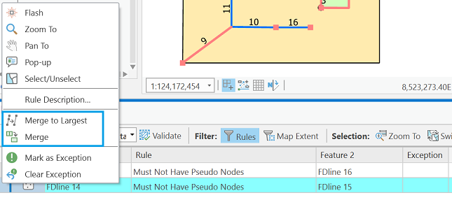 Figure 5.17: The menu that comes up when you right-click on an entry of the Error Inspector pane.
 - There is a second violation of the Must Not Have Pseudo Nodes error. Highlight it via the Error Inspector. You'll see that it is where line features 8, 14, and 15 are supposed to meet. If you zoom in far enough on that intersection, you will see that line 8 is not snapped at the intersection of lines 14 and 15.
- It turns out that one of our other rules would have also highlighted an error in that same area. Do you know which one? Click the Rules button again and select FDline - Must Not Have Dangles.
- In the list of errors, click the row where Feature 1 is equal to 8. That should also highlight a vertex in the vicinity of where line feature 8 is supposed to be snapped at the intersection of lines 14 and 15. Which vertex is highlighted? It is the end vertex of line feature 8.
The list of Must Not Have Dangles errors contains 10 entries. It is important to realize that not all dangling line feature endpoints are actually errors. It is acceptable to have dead end streets, for example. - It is also important to realize that the Must Not Have Dangles rule only pertains to features in a single layer. If you click through the list of dangle errors, you will see that three of the entries on the list are where line features 7, 8, and 9 meet the corners of polygon 11 (the FDpolygon_2 feature). If you do some investigating, you will find that the end of line 7 is indeed snapped to the corner vertex of polygon 11. Even so, the geodatabase topology still flags it as a possible error.
- Now, let's look at the FDpolygon_1 - Must Not Have Gaps error results.
Select it from the Rules picklist in the Error Inspector. You should see two results listed in the Error Inspector represented by the Line Error symbol. - One of the Error Inspector entries, when chosen from the list, will show the result depicted in the image below (Figure 5.18).
Click on the entries until you find it.
Part of the description of this topology rule includes the following: "An error will always exist on the perimeter of the surface. You can either ignore this error or mark it as an exception." Figure 5.18: The view of the FDpolygon_1 data after you choose the desired Must Not Have Gaps entry in the Error Inspector.
 - Let's mark this as an exception.
Right-click on the error entry in the Error Inspector table and choose Mark As Exception. An exclamation point icon will appear in the Exception column and if you select a different error, you'll see that what had been a pink outline, indicating an error, has changed to a green outline, indicating that it's been marked as an exception. - Select the error that highlights the boundary between polygons 2 and 5, then click the Error Inspector's Zoom To button. Toggle the topology layer's visibility off for the moment so that you're able to see the polygon boundaries. When you zoom in far enough, you should discover a gap between FDpolygon_1 polygons 2 and 5. Someone did not do a good job of making sure the FDpolygon_1 features shared boundaries.
Let's stick with the FDpolygon_1 polygon layer and perform an edit. While we are at it, we will learn how to highlight areas in our data that have been modified/edited. These "dirty areas," as they are referred to, let us know that we should validate the topology again. - Zoom back out to Full Extent.
In the Error Inspector, select the FDpolygon_1 - Must Not Overlap rule. There should be two errors. We are going to focus on the one involving polygons 2 and 3. - Again making sure the topology layer is turned off, zoom in on the location of the overlap error between polygons 2 and 3 until you have a good view of the overlap. You could elect to change the display of the layer to "Hollow" in order to see the overlap more definitely.
- Let's rectify the overlap using the canned error correction choice provided by the Error Inspector. Right-click on the error in the Error Inspector and select Merge from the menu.
- In the Merge window that opens, click on each of the two entries. Doing so will cause the polygon that the overlap area will be merged with to be flicker-highlighted.
- Choose the first of the two -- for polygon feature 2, and then click the Merge button.
- If you still have the display of the TopolExFeatureDataset_Topology layer un-checked, check the box now. Also turn on the display of the Dirty Areas Polygon 3 should be highlighted in the hatch pattern, indicating that it is a dirty area -- that a change has been made since the topology rules were last validated.
- Click the Validate button again. The hatched area should disappear, indicating that the error has been correctly dealt with as far as our topology rules are concerned. Also note that there should be only one overlap error left.
- You should save your edits now (Edit > Save).
- Deliverable- I want to see that you were able to perform the correction we just went though, so zip up your geodatabasetopol.gdb geodatabase and upload it to the Project 5 Drop Box.
You should be getting a feel for how to interact with the Error Inspector.
Go ahead and spend some time investigating the other rules infractions to see if you can determine the reasons for the other error symbols that you see on the map.
- Why is there a Point Error at the bottom-left corner of the FDpolygon_1 polygon 5 feature (point 3)?
- Why is line 9 highlighted?
- etc.
If you want, attempt to correct some of the other errors. Not all of them (like the gap we found between the two polygons) have canned fixes via the Error Inspector. So if you are pining away for a chance to do some editing, be my guest.
I leave it up to you to choose whether or not to save the project, and any edits you make.
B. Using topology editing tools with shared polygon boundaries
With a geodatabase topology in place, there are certain tools at your disposal that enable you to maintain topological relationships when you make edits to spatial data. Here, we contrast editing a shared polygon boundary with and without having a geodatabase topology set up. It is important to realize that the "shared" boundary between two polygons actually is a duplicate set of line segments, each polygon boundary exists as complete and independent from the adjacent polygon. So, when a shared boundary needs to be edited, one must actually edit the boundaries of two polygons.
- First, we will look at the case where we have no topology imposed on the data, and we attempt to edit a shared polygon boundary with the Vertices tool
 . The images below illustrate what happens. Because the edit is conducted with No Topology, only one of the polygon's vertices can be moved at a time. The images depict a simple case, but think of a situation where three or four polygons share a common corner vertex.
 Figure 5.19: Two polygon features in a geodatabase feature class that share a boundary.
 Figure 5.20: The result of editing/moving one vertex when conducted with No Topology.
 - With a topology in place, the capabilities of the Vertices tool are extended a bit. In the Modify Features pane to the right of the map, an Edges tab appears in addition to the Features tab. By clicking the Edges tab, you can then select a shared edge that you'd like to modify. In the first of the two figures below, the shared edge is shown selected after having clicked the Edges tab. In the second figure, you can see that the same vertex moved in Figure 5.20 has been moved again. This time, both polygon boundaries are edited at the same time.
 Figure 5.21: With a geodatabase topology in place, and the shared boundary selected prior to moving the vertex.
 Figure 5.22: The result of editing/moving two shared vertices when a geodatabase topology is in place.
C. Project - Given a single feature class in a geodatabase, set up a geodatabase topology and deal with a single class of error
Because this is not a course in inputting and editing spatial and attribute data, we are choosing to focus on what needs to be done to prepare to implement a geodatabase topology. There will be some errors in spatial data to repair, but it involves going over ground already covered in section A of the lesson.
Unzip the TopologyProject.zip archive. The archive contains a folder named TopologyProject. Within that folder is a geodatabase (TopologyProject.gdb) and a georeferenced image of a map (with ancillary files).
The BuildingFootprints feature class contains some instances of polygon overlap that need to be repaired.
In order for you to accomplish finding and repairing the errors in the BuildingFootprints feature class, you are going to have to create and employ a geodatabase topology. You know from section A how to create a geodatabase topology, and you know that in order to do so, the data in question has to reside within a feature dataset. What we did not explicitly go over in the lesson was how to (1) create a feature dataset, and (2) how to get existing data, in this case the feature class contained in the TopologyProject.gdb, into a feature dataset that we create. But that's what I want you to do. Given that Geography 484 or comparable experience was the prerequisite for taking this course, you should be able to do it.
Once you have accomplished that, proceed to find and correct the overlapping building footprint polygons. All of the offending features will be in the area covered by the included georeferenced map image. You can use it as reference to make sure you are performing the corrections to the polygons correctly.
When you finish, zip up your version of the TopologyProject.gdb and upload it to the Lesson 5 Drop Box.