To this point in the lesson, we have discussed Rock Properties and Fluid Properties, but we must also discuss how the rock and different fluids interact. In other words, how does the rock interact with the fluids and how do the various fluids interact with each other? At the pore and capillary scales, these interactions occur through the various attractive and repulsive forces acting on each component in the system (rock and fluids). These pore-scale forces include capillary forces, surface tensions, interfacial tensions, van der Waal forces, etc. While these topics are interesting in their own right, as engineers, we are interested in how these pore and capillary scale forces manifest themselves at a much larger macro-scale.
Phase Saturations, So, Sg, and Sw
To start the discussion about rock-fluid interaction properties, we must first define the phase saturations, So, Sg, and Sw, in the reservoir. The phase saturation is defined as the fraction of the pore volume occupied by a particular phase. For example, if the pore-volume of a porous medium by 65 percent oil, 25 percent gas, and 10 percent water, then the phase saturations would be:
- So = 0.65
- Sg = 0.25
- Sw = 0.10
Thus, if we had a core sample of rock with a bulk volume, Vb = 200.0 cc, an effective porosity, ϕ = 0.22, and the phase saturations listed above, then the core sample would contain:
- Vo=So Vp=SoϕVb = (0.65)(0.22)(200.0 cc) = 28.6 cc of oil
- Vg=Sg Vp=SgϕVb = (0.25)(0.22)(200.0 cc) = 11.0 cc of gas
- Vw=Sw Vp=SwϕVb = (0.10)(0.22)(200.0 cc) = 4.4 cc of water
where Vo, Vg, and Vw are the volumes of oil, gas, and water, respectively, in the core sample. By definition, the phase saturations must always sum to 1.0:
This relationship is known as the Saturation Constraint.
Capillary Pressure, pcow and pcgo
It has been observed that when two or more immiscible fluids occupy the pore-volume and capillaries of a porous medium, the pressures of the different phases are not equal, but are different from each other. This macro-scale phenomenon, known as capillary pressure, is due to interactions of the surface and interfacial tensions of the rock and fluids in the confined dimensions of the rock pores and capillaries. A force balance on the surface and interfacial tensions require that the pressures of the various phases are different. At the macro-scale, this phenomenon is quantified with the Capillary Pressure Relationships:
and
As shown in Equation 3.77 and Equation 3.78, the capillary pressure is the difference between the two phase pressures and is a function of the phase saturations. As written, these equations assume that the reservoir rock is Water Wetting Surface (the surface of the rock preferentially favors contact with the water phase). If we were to write these equations for an Oil Wetting Surface (the surface of the rock preferentially favors contact with the oil phase), then we would have:
and
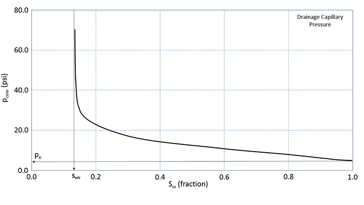
We will not go into the details of Wettability, Water Wetting Surfaces, or Oil Wetting Surfaces; however, water wet reservoirs are the more common for petroleum rocks, and we will focus on them (Equation 3.77 and Equation 3.78). Please note that while water wetting rocks are the more common for reservoir rock lithologies, there are many examples of oil wet rocks in the petroleum literature. Figure 3.13 shows a typical drainage capillary pressure relationship for a water wet rock.
In Figure 3.13, the solid line is the drainage capillary pressure curve for a wetting phase (in our case, water in a water-wet rock). The capillary pressure, pe, is the Entry Pressure which is the pressure that is required to force a non-wetting phase (in our case, oil in a water-wet rock). The entry pressure is the pressure that is required to force the first drop of oil into the water-wet rock. Remember, the term “water-wet” implies that the rock has a preference to stay in contact with water. The entry pressure is the pressure required to overcome this preference. At some value of water saturation, the capillary pressure measurements begin to go asymptotic to the vertical. This water saturation, Swir, is the Irreducible Water Saturation and represents the minimum water saturation that the reservoir rock can reach in the presence of an oil phase. As indicated in this figure, irreducible water saturation is caused by capillary forces acting on the oil, water, and rock components of the system.
In this figure, the term “Drainage Capillary Pressure” appears; this refers to the manner in which the data were measured. There are two ways that we can measure capillary pressure. We could first fill the core sample with the wetting phase (in our case, water) and measure the capillary pressure by increasing the saturation of the non-wetting phase (in our case oil). This is identical to decreasing the saturation of the wetting-phase. This process, where the wetting phase saturation is decreased, is referred to as a Drainage Process and represents processes where the wetting phase is allowed to “drain” from the rock.
Alternatively, we could have first filled the core sample with the non-wetting phase (in our case, oil) and measured the capillary pressure by increasing the saturation of the wetting phase (in our case, water). This process, where the wetting phase saturation is increased, is referred to as an Imbibition Process and represents processes where the wetting phase is allowed to “imbibe” into the core. Both processes, drainage processes and imbibition processes, occur in oil and gas reservoirs.
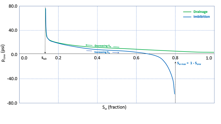
It turns out that when you conduct the experiment using these two processes, you get different results. When this phenomenon occurs (measurements are dependent on the saturation history – increasing or decreasing wetting phase saturation), it is referred to as Hysteresis. Typical results for oil-water drainage and imbibition capillary pressure measurements including the impact of hysteresis are shown in Figure 3.14.
In Figure 3.14, we see that as we increase the saturation during an imbibition measurement cycle, the water saturation reaches an asymptotic maximum value, Sw max (or, 1 - Sorw). This trapped oil saturation, Sorw, is called the Residual Oil Saturation to Water and is the result of capillary forces occurring in the reservoir rock. We will discuss these end-point saturations, Swir and Sorw, in more detail when we discuss relative permeabilities.
While both drainage processes and imbibition processes occur in the reservoir, the topic of hysteresis is beyond the scope of this course. For this course, we will focus on the drainage capillary pressure of water wet reservoirs.
In the laboratory, capillary pressures are measured using Special Core Analysis (also known as SCAL) methods and must be specifically requested from the core laboratory. The drainage capillary pressure curves (Figure 3.13 and green curve in Figure 3.14) can be estimated from the Brooks-Corey Model[15]:
Where:
- pcow is the oil-water capillary pressure, psi
- λ is the pore-size distribution, dimensionless
- po and pw are the pressures of the oil phase and water phase, respectively, psi
- pe is the entry pressure, psi
- Sw is the water (wetting) phase saturation, fraction
- Swir is the irreducible water saturation, fraction
In the Brooks-Corey Model[15], λ, Swir, and pe can be obtained from the capillary pressure data. In addition, Swir can be obtained from open-hole well logs or by relative permeability data.
Relative Permeability, krow and krw
We have already discussed Darcy’s Law in the context of single-phase flow and absolute permeability. Darcy’s Law, Equation 3.24, was written earlier as:
Where qf is the volumetric flow rate in bbl/day, and all of the properties used in Equation 3.24 were discussed earlier. Note that we can convert the units of flow rate in Darcy’s Law from bbl/day to STB/day by the inclusion of the formation volume factor of the flowing fluid, Bf:
One of the assumptions listed with these versions of Darcy’s Law was that the flowing fluid is an incompressible, homogeneous, Newtonian fluid that fully saturates (single-phase) the porous medium. As we have already seen, the flow of fluids in real petroleum reservoirs is typically up to three-phase flow, and in some rare instances, may be as high as four-phase flow.
For multi-phase flow, we can rewrite Equation 3.82 for each of the phases present, regardless of whether the fluids are mobile or are stationary (we only care about their presence). Assuming three phases; oil, water, and gas, we have:
and
Note that we have assigned a phase designation to both the pressure, pf, and the permeability, kf. As discussed earlier, due to the capillary pressures, each of the phases present in the reservoir may have a different pressure, and consequently, we must distinguish between pressures (and pressure gradients) that are specific to each phase.
When we write a permeability value that is specific to an individual phase, kf, that permeability is referred to as the Effective Permeability to that phase. Therefore, in Equation 3.83, we have the effective permeability to oil, the effective permeability to water, and the effective permeability to gas (ko, kw, and kg, respectively).
The effective permeability is defined as the permeability to a specific phase in the presence of one or more other phases. These effective permeabilities, kf, are related to the absolute permeability, k, appearing in Equation 3.24 and Equation 3.82 through the Relative Permeability Relationships:
and
Where:
- kro, krw, and krg are the relative permeabilities to oil, water and gas, respectively, fraction
- k is absolute permeability (permeability for single-phase flow: Equation 3.24 and Equation 3.82), md
Substituting Equation 3.84 into these into Equation 3.83:
and
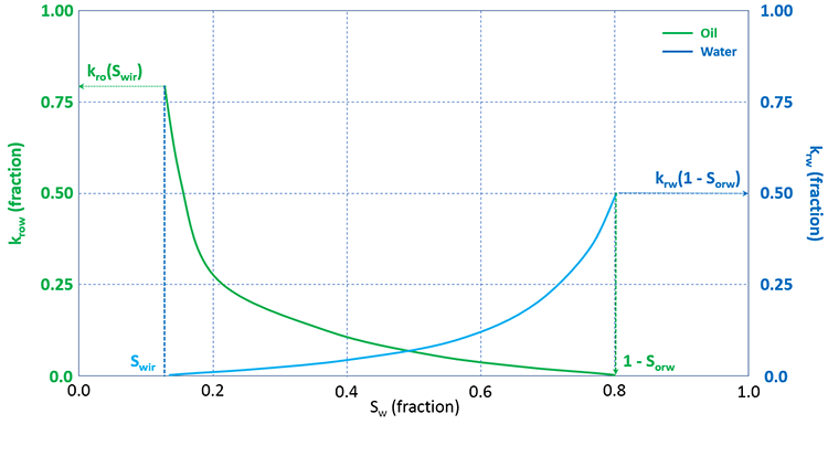
Relative permeabilities are functions of the phase saturations. A typical set of oil-water relative permeability curves is shown in Figure 3.15.
In Figure 3.15, the water saturation is plotted on the x-axis. The most important features that can be seen in this figure are the trends of the relative permeability curves. As the water saturation increase, the relative permeability to oil decreases while the relative permeability to water increases. This is because as the water saturation increases, fewer pathways become available for oil to flow while more pathways become available for water to flow.
In this figure, the parameters of irreducible water saturation, Swir, and residual oil saturation to water, Sorw, are identical to the values discussed earlier in the section on capillary pressure curves and shown in Figure 3.14. The water saturation range, Swir ≤ Sw ≤ 1 – Sorw, represents the range in which both the oil and water are mobile. Note that outside of this range, one of the relative permeability values is equal to zero, from Equation 3.85 a zero value of relative permeability implies that the flow rate will be zero.
On this plot, we can see that the maximum water saturation, Sw max = 1 – Sorw. We use this terminology because, as stated, the x-axis is the water saturation; while Sorw is an oil saturation. In other words, from Figure 3.15 we can see that Sorw is approximately 0.2, while due to the saturation constraint, ∑f=o,wSf = 1, Sw max must be 0.8.
For a two-phase, oil-gas system we have a somewhat similar set of relative permeability curves as with the two-phase, oil-water system. Figure 3.16 shows a typical set of gas-oil relative permeability curves.
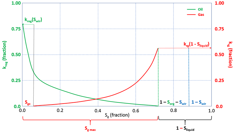
In the gas-oil relative permeability curves, the gas saturation, Sg, is plotted on the x-axis. There are several important differences between the oil-gas system and the oil-water system that must be further discussed. One difference is the critical gas saturation, Sgc. The critical gas saturation is similar to Swir for water, in that it represents the value at which gas will begin to flow in situations the gas saturation is increasing (or, conversely, the saturation at which gas will stop flowing in situations the gas saturation is decreasing). We can also see oil is present and is mobile below Sgc (it has finite values below Sgc). This is because of the dissolved gas in the oil phase. As gas comes out of solution from a mobile oil phase, the gas saturation needs to build up to Sgc before it can begin to flow. While this is occurring, the oil phase remains mobile. Therefore, for gas-oil systems, oil is mobile in the range 0 ≤ Sg ≤ 1 – Sorg – Swir, and gas is mobile in the range Sgc ≤ Sg ≤ 1 – Sorg – Swir.
A second difference between the oil-water curves and the gas-oil curves is the use of the term krow in Figure 3.15 and the term krog in Figure 3.16. This is because the relative permeabilities to oil are different when measured in an oil-water system and in a gas-oil system. The is also true for the residual oil saturations, Sorw and Sorg. These differences are due to the differences in the surface tensions and resulting capillary forces between oil and water and between gas and oil.
A third difference is due to the irreducible water saturation, Swir. As we have already discussed, the irreducible water saturation is the lowest water saturation in the reservoir. Since all real oil and gas reservoirs contain water, the initial water saturation in these reservoirs, Swi, must be at least equal to the irreducible water saturation, Swir, or greater: Swi ≥ Swir. Therefore, to get representative laboratory measurements or calculations from correlations, we must include Swir in the analyses. Therefore, when we take laboratory measurements for gas-oil curves, we take them in the presence of an immobile, irreducible water saturation. Also note the application of the saturation constraint for the liquid (oil and water) saturations.
Relative permeability measurements also require special laboratory techniques and must be requested as a part of Special Core Analysis procedures when ordering tests from a core laboratory. There are two general approaches for laboratory measurements of relative permeability, the Unsteady State Method and the Steady State Method. Of the two methods, the Steady State Method (also known as the Penn State Method) is the more accurate laboratory procedure; however, it takes more time (and money) to perform these tests.
When laboratory data are not available, then the relative permeabilities can be calculated using a Power Law Model.
For oil-water curves, we have:
and
While for gas-oil systems we have:
and
Where:
- krow is the relative permeability to oil measured in an oil-water system, fraction
- krw is the relative permeability to water measured in an oil-water system, fraction
- krog is the relative permeability to oil measured in a gas-oil system in the presence of an irreducible water saturation, fraction
- krg is the relative permeability to gas measured in a gas-oil system in the presence of an irreducible water saturation, fraction
- krow(Swir) is the relative permeability to oil at the irreducible water saturation measured in an oil-water system, fraction
- krw(1 – Sorw) is the relative permeability to water at the maximum water saturation, measured in an oil-water system, fraction
- krog(Swir) is the relative permeability to oil at the irreducible water saturation measured in a gas-oil system in the presence of an irreducible water saturation, fraction
- krg(1 – Sliquid) is the relative permeability to gas at the maximum gas saturation, 1 – Sorg – Swir, in a gas-oil system in the presence of an irreducible water saturation, fraction
- So, Sw, and Sg are the oil, water, and gas saturations, respectively, fraction
- Swir is the irreducible water saturations, fraction
- Sorw is the residual oil saturation to a water displacement
- Sorg is the residual oil saturation to a gas displacement in a gas-oil system in the presence of an irreducible water saturation, fraction
- Sgc is the critical gas saturation where gas begins to flow in a gas-oil system in the presence of an irreducible water saturation, fraction
- now and nw are oil and water exponents, respectively, in an oil-water system (these exponents are referred to as Corey Exponents), dimensionless
- nog and ng are oil and gas exponents, respectively, in a gas-oil system in the presence of an irreducible water saturation (these exponents are also referred to as Corey Exponents), dimensionless
Most of these values can be seen in Figure 3.15 and Figure 3.16. Note that all of the groups in the parenthesis in Equation 3.86 through Equation 3.87 go from 0.0 to 1.0 in their respective mobile saturation ranges. These groups are often referred to as Normalized Saturations.
[15] Brooks, R.H. and Corey, A.T. 1964. Hydraulic Properties of Porous Media. Hydrology Paper No. 3, Colorado State University, Fort Collins, Colorado, 22–27.